Sign In
Upload
Manuals
Brands
Brookfield Manuals
Measuring Instruments
TT100
Brookfield TT100 Manuals
Manuals and User Guides for Brookfield TT100. We have
1
Brookfield TT100 manual available for free PDF download: Installation, Operation And Maintenance Instructions
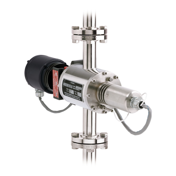
Brookfield TT100 Installation, Operation And Maintenance Instructions (134 pages)
IN-LINE VISCOMETER
Brand:
Brookfield
| Category:
Measuring Instruments
| Size: 1.41 MB
Table of Contents
Table of Contents
3
Section 1 - In-Line Viscometer Description
9
Introduction
9
Features and Benefits
9
Appendix D - Agency Approvals
11
Appendix E - Warranty Information
11
Figure 1-1: Typical TT100 In-Line Viscometer with Oriental Motor
11
Figure 1-2: Typical TT100 In-Line Viscometer with Groschopp Motor
12
Theory of Operation
13
Figure 1-3: TT100 In-Line Viscometer Product Stream Flow
13
Correlation with Other Measurements
14
Figure 1-4: In-Line Viscometer Correlation with Other Measurement
14
Specifications
15
Table 1-1:Model TT100 In-Line Viscometer Specifications
15
Required Utilities
16
Current Draw - Starting & Running
16
Table 1-2:Utility Requirements
16
Cleaning
17
Component Identification
18
Torque Sensor Assembly
18
Sensing Endcap
18
Stator
18
Stop Posts
18
Inlet/Outlet
18
Rotor
18
Drive Endcap
19
Motor Cable
19
Gearbox
19
Drive Motor
19
Drive Coupling
19
Bleed Screw
19
Measuring Chamber
19
Measuring Annulus
19
Sensing Cable
20
Torsion Element
20
Heat Baffle
20
Torque Sensor Electronics Enclosure
20
Motor Control Enclosure
21
Figure 1-5: Typical Model TT100 In-Line Viscometer Component
21
Options
22
Double Mechanical Seal
22
Elliptical Baffle
22
Perforated Rotor
22
Serrated Stator
22
Flushing Endcap
22
Accessories
23
Section 2 - Installation
25
Unpacking and Inspection
25
Installation Requirements
25
Calculating Minimum Straight Pipe Length
27
Installation
27
Figure 2-1: Typical In-Line Viscometer Installation
28
Figure 2-2:NEMA 4 - 115 or 230 VAC 50/60 Hz Installation
29
Figure 2-3:NEMA 7 - Explosion Proof 115 VAC 50/60 Hz Installation
30
Figure 2-4:CENELEC - 115 or 230 VAC 50/60 Hz Installation
31
Flushing Connections
32
Section 3 - Calibration
33
Introduction
33
Tools Required
34
Table 3-1:Tools Required
34
Figure 3-1: Typical Installation Calibration Flowchart
35
Figure 3-2: Typical Calibration after Viscometer Disassembly and Cleaning
36
Figure 3-3:Typical Calibration after Component Replacement
37
Fine Zero Milliampere Calibration Test
38
Figure 3-4:Torque Sensor Electronics Board Adjustment Component
39
Preliminary Torque Sensor Test
40
Figure 3-5: Applying Torque to the Stator
41
Single Range Viscometer Span Calibration
42
Figure 3-6: Calibration Bar Installation
44
Dual Range Viscometer Span Calibration
46
Figure 3-7: Calibration Bar Installation
48
Coarse Zero Calibration
50
Figure 3-8: Microsyn Field Coil Assembly Rotation
51
Figure 3-9: Stator Direction of Rotation
52
Fine Zero Voltage Calibration
53
Section 4 - Operation
55
Introduction
55
Mechanical Seal Requirements
55
Normal Operation Observations
56
Interlocks
56
Start-Up
57
Shutdown
58
Section 5 - Maintenance
59
Introduction
59
Clean-In-Place
59
Flushing
60
Disassembly and Cleaning
61
Cleaning the Sensing Endcap Assembly
61
Cleaning the Drive Endcap Assembly and Measuring Chamber
65
Reassembly
66
Elliptical Baffle Precautions
67
Section 6 - Service
69
Introduction
69
Tools Required
70
Table 6-1:Tools Required
70
Sensing Endcap Service
71
Disassembly
71
Microsyn Field Coil Replacement
76
Torque Sensor Printed Circuit Board Replacement
77
Torsion Element Replacement
79
Sensing Endcap Assembly
81
Drive Endcap Service
84
Motor and Gearbox Test
84
Disassembly
87
Capacitor Replacement
91
Oriental Motor Replacement
91
Oriental Motor Gearbox Replacement
92
Groschopp Motor Replacement
92
Groschopp Motor Gearbox Replacement
93
Bearing Replacement
94
Drive Endcap Assembly
96
Double Mechanical Seal Assembly Replacement
96
Appendix A - Customer Support
101
Appendix B - Drawings
101
Appendix C - Viscosity Range Change
101
Introduction
101
Table 7-1:Process Fluid Leaks
101
Table 7-2:Drive Motor
102
Table 7-3:Calibration Errors
103
Table 7-4:Correlation/Application
105
Changing Range or Shear Rate
119
Speed of Rotation Change
120
Stator Change
120
Torsion Element Change
121
Electronic Change
121
Summary
121
Table C-1:Shear Rates and Factors for 2.440 ID Rotor
122
Table C-2:Shear Rates and Factors for 1.450 ID Rotor
122
Table D-1:Agency Approvals - TT100 In-Line Process Viscometer
123
Section 7 - Troubleshooting
101
Advertisement
Advertisement
Related Products
Brookfield T-A
Brookfield T-F
Brookfield Thermosel DV-III+
Brookfield Thermosel LVDV-E
Brookfield Thermosel HADV-I+
Brookfield Thermosel LVT
Brookfield Thermosel RVT
Brookfield Thermosel HAT
Brookfield Thermosel HBT
Brookfield Thermosel RVDV-II+
Brookfield Categories
Measuring Instruments
Temperature Controller
Laboratory Equipment
Door Opening System
More Brookfield Manuals
Login
Sign In
OR
Sign in with Facebook
Sign in with Google
Upload manual
Upload from disk
Upload from URL