
Related Manuals for Tenma 72-10405


Summary of Contents for Tenma 72-10405
- Page 1 72-10405 72-14625 72-10415 Operating Manual Digital Multimeters P/N:110401108731X REV.0 DATE:2019/3/2...
-
Page 2: Table Of Contents
Model 72-10405/72-14625/72-10415: OPERATING MANUAL Table of Contents Title Page Overview Unpacking Inspection Safety Information Rules For Safe Operation International Electrical Symbols The Meter Structure Rotary Switch Functional Buttons Display Symbols Measurement Operation A.DC/AC Voltage Measurement B.DC/AC Current Measurement C.Measuring Resistance D.Testing for Continuity... - Page 3 Model 72-10405/72-14625/72-10415: OPERATING MANUAL Title Page Operation of Hold Mode RANGE Button MAX MIN Button PEAK Button Data Outputting The Use of Relative Value Mode The BLUE Button Turning on the Display Backlight Sleep Mode General Specifications Accuracy Specifications A.DC Voltage B.AC Voltage...
- Page 4 Model 72-10405/72-14625/72-10415: OPERATING MANUAL Title Page F.Capacitance G.Frequency H.Diode Test I.Continuity Test J.Temperature A.Replacing the Battery B.Replacing the Fuses...
-
Page 5: Overview
This Operating Manual covers information on safety and cautions. Please read the relevant information carefully and observe all the Warnings and Notes strictly. Warning Model 72-10405, 72-14625, and 72-10415 On addition to the measuring functions, this meters includes a USB interface, data hold, relative mode, peak measurement, low battery indication, backlit display, and sleep mode. -
Page 6: Unpacking Inspection
Model 72-10405/72-14625/72-10415: OPERATING MANUAL Except where noted, the descriptions and instructions in this Operating Manual apply to all models 72-10405, 72-14625, and 72-10415 . Unpacking Inspection Open the package case and take out the Meter. Check the following items carefully... -
Page 7: Safety Information
Model 72-10405/72-14625/72-10415: OPERATING MANUAL In the event you find any missing or damage, please contact your dealer immediately. Safety Information This Meter complies with the standards IEC61010: in pollution degree 2, overvoltage category (CAT. III 1000V, CAT. IV 600V) and double insulation. -
Page 8: Rules For Safe Operation
Model 72-10405/72-14625/72-10415: OPERATING MANUAL Rules For Safe Operation Warning To avoid possible electric shock or personal injury, and to avoid possible damage to the Meter or to the equipment under test, adhere to the following rules: l Before using the Meter inspect the case. Do not use the Meter if it is damaged or the case (or part of the case) is removed. - Page 9 Model 72-10405/72-14625/72-10415: OPERATING MANUAL l Do not use or store the Meter in an environment of high temperature, humidity , explosive, inflammable and strong magnetic field. The performance of the Meter may deteriorate after dampened. l When using the test leads, keep your fingers behind the finger guards.
-
Page 10: International Electrical Symbols
Model 72-10405/72-14625/72-10415: OPERATING MANUAL l Turn the Meter off when it is not in use and take out the battery when not using for a extended amount of time. l Constantly check the battery as it may leak when it has been using for some time, replace the battery as soon as leaking appears. -
Page 11: The Meter Structure
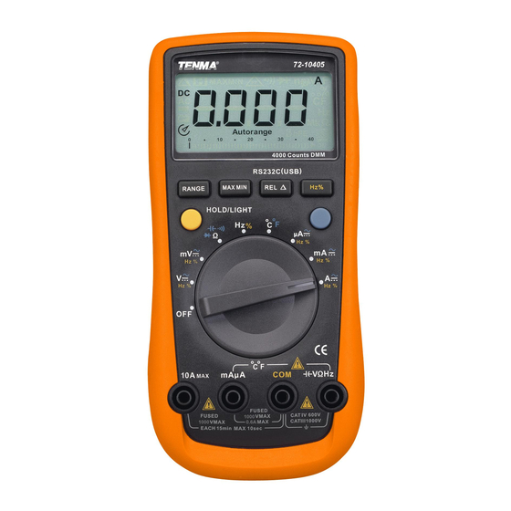
Model 72-10405/72-14625/72-10415: OPERATING MANUAL LCD Display Functional Buttons Blue button Rotary Switch Input Terminal: figure 1... -
Page 12: Rotary Switch
DC Voltage Measurement (72-14625 only) Resistance Measurement Diode Test Continuity Test Capacitance Test Frequency and Duty Cycle Test Temperature in Celsius (72-10405 only) Temperature in Fahrenheit (72-10405 only) DCA and ACA Measurement DCmA and ACmA Measurement 10A DC and AC Measurement Power off... -
Page 13: Functional Buttons
Model 72-10405/72-14625/72-10415: OPERATING MANUAL Functional Buttons Below table indicated for information about the functional button operations. Button Operation Performed Press and hold for 2 serconds to turn the display backlight on or off. (72-10405 and 72-14625 only) Press to enter or exit data hold mode. -
Page 14: Display Symbols
Model 72-10405/72-14625/72-10415: OPERATING MANUAL... - Page 15 Model 72-10405/72-14625/72-10415: OPERATING MANUAL...
-
Page 16: Measurement Operation
Model 72-10405/72-14625/72-10415: OPERATING MANUAL Measurement Operation A. DC/AC Voltage Measurement (See figure 2) figure 2... - Page 17 Model 72-10405/72-14625/72-10415: OPERATING MANUAL 72-10405 72-14625 and 72-10415 If online frequency and duty cycle values are needed at this moment, only press Hz/% button to obtain relative data. However input amplitude concerning these two aspects should follow requirements as below:...
- Page 18 If the circuit impedance is less than or equal to 10k , the error is negligible (0.1% or less). l For 72-10405:When measuring mV, you must press RANGE manually to enter mV range. l When voltage measurement has been completed, disconnect the connection between the testing leads and the circuit under test, and remove the testing leads away from the input terminals of the Meter.
-
Page 19: B.dc/Ac Current Measurement
Model 72-10405/72-14625/72-10415: OPERATING MANUAL B. DC/AC Current Measurement (See figure 3) figure 3... - Page 20 Model 72-10405/72-14625/72-10415: OPERATING MANUAL Warning Before connecting the Meter to the return circuit to be tested, cut off the current of the return circuit. If the fuse burns out during measurement, the Meter may be damaged or the operator himself may be hurt.
- Page 21 Model 72-10405/72-14625/72-10415: OPERATING MANUAL 72-10405: display effective value of sine wave (mean value response). 72-14625 and 72-10415: display true rms value. 5. Press Hz% to obtain the frequency and duty cycle value. Input Amplitude: (DC electric level is zero) Input Amplitude: range 30%...
-
Page 22: C.measuring Resistance
Model 72-10405/72-14625/72-10415: OPERATING MANUAL C. Measuring Resistance (See figure 4) figure 4... - Page 23 Model 72-10405/72-14625/72-10415: OPERATING MANUAL Warning To avoid damages to the Meter or to the devices under test, disconnect circuit power and discharge all the high-voltage capacitors before measuring resistance. To avoid harm to yourself, do not input higher than DC 60V or AC 30V voltages.
- Page 24 Model 72-10405/72-14625/72-10415: OPERATING MANUAL...
-
Page 25: D.testing For Continuity
Model 72-10405/72-14625/72-10415: OPERATING MANUAL D. Testing for Continuity (See figure 5) figure 5... - Page 26 The buzzer does not sound if the resistor to be tested is >35 Note l 72-10405 and 72-14625: open circuit voltage is around 0.45V 72-10415: open circuit voltage is around -1.2V l When continuity testing has been completed, disconnect the connection...
-
Page 27: E.testing Diodes
Model 72-10405/72-14625/72-10415: OPERATING MANUAL E. Testing Diodes (See figure 6) figure 6... - Page 28 Model 72-10405/72-14625/72-10415: OPERATING MANUAL...
- Page 29 Model 72-10405/72-14625/72-10415: OPERATING MANUAL l Connect the test leads to the proper terminals as said above to avoid error display. The LCD will display OL indicating diode being tested is open or polarity is reversed. The unit of diode is Volt (V), displaying the forward voltage drop readings.
-
Page 30: F.capacitance Measurement
Model 72-10405/72-14625/72-10415: OPERATING MANUAL F. Capacitance Measurement (See figure 7) figure 7... - Page 31 72-14625...
- Page 32 Model 72-10405/72-14625/72-10415: OPERATING MANUAL n the tested capacitor is more than 100uF figure 8...
- Page 33 Model 72-10405/72-14625/72-10415: OPERATING MANUAL 72-10405 and 72-14625: 72-10415: 40MHz:unspecified For 72-10415:Measuring Audio frequency,if the input voltage is more than 15 volt. the meter will simulate the sound in same frequency.
-
Page 34: H.temperature Measurement
When frequency measurement has been completed, disconnect the connection between the testing leads and the circuit under test, and remove the testing leads away from the input terminals of the Meter. H. Temperature Measurement (72-10405 only) (See figure 9) figure 9) - Page 35 Model 72-10405/72-14625/72-10415: OPERATING MANUAL Warning To avoid harm to yourself, do not input higher than DC 60V or AC 30V voltages. To measure temperature, connect the Meter as follows: 1. Set the rotary switch to 2. Insert the temperature probe into the input terminal as shown on the figure 9.
-
Page 36: Operation Of Hold Mode
Model 72-10405/72-14625/72-10415: OPERATING MANUAL Operation of Hold Mode Warning To avoid possibility of electric shock, do not use Hold mode to determine if circuits are without power. The Hold mode will not capture unstable or noisy readings. The Hold mode is applicable to all measurement functions. -
Page 37: Range Button
Press and hold RANGE for over 2 seconds to return to autoranging; the Meter beeps. MAX MIN button (72-10405 and 72-14625 only) l Press MAX MIN to start recording of maximum and minimum values. Steps the display through high (MAX) and low (MIN) readings. The Meter enters manual ranging mode after pressing MAX MIN button. -
Page 38: Data Outputting
Model 72-10405/72-14625/72-10415: OPERATING MANUAL 72-10405 72-10415... -
Page 39: The Blue Button
Model 72-10405/72-14625/72-10415: OPERATING MANUAL 72-10405 and 72-14625 only 72-10405 only... -
Page 40: General Specifications
Model 72-10405/72-14625/72-10415: OPERATING MANUAL 600m 1000V Φ6.35x31.8mm 1000V Φ10.3x38.1mm... -
Page 41: Accuracy Specifications
Model 72-10405/72-14625/72-10415: OPERATING MANUAL... -
Page 42: A.dc Voltage
Model 72-10405/72-14625/72-10415: OPERATING MANUAL 72-10405 72-10405... - Page 43 Model 72-10405/72-14625/72-10415: OPERATING MANUAL 72-14625 72-10415...
-
Page 44: B.ac Voltage
Model 72-10405/72-14625/72-10415: OPERATING MANUAL 72-10405 72-10405... - Page 45 72-14625...
- Page 46 Model 72-10405/72-14625/72-10415: OPERATING MANUAL 72-10415...
-
Page 47: C.dc Current
Model 72-10405/72-14625/72-10415: OPERATING MANUAL F600mA H 1000V, 6.35 x 31.8mm 1000V, 10.3 x 38.1mm... - Page 48 Model 72-10405/72-14625/72-10415: OPERATING MANUAL 72-14625 600mA H 1000V, 6.35 x 31.8mm 1000V, 10.3 x 38.1mm...
- Page 49 Model 72-10405/72-14625/72-10415: OPERATING MANUAL 600mA H 1000V, 6.35 x 31.8mm 10A H 1000V, 10.3 x 38.1mm...
-
Page 50: D.ac Current
Model 72-10405/72-14625/72-10415: OPERATING MANUAL 600mA H 1000V, 6.35 x 31.8mm 10A H 1000V, 10.3 x 38.1mm... - Page 51 Model 72-10405/72-14625/72-10415: OPERATING MANUAL 72-14625 72-14625 600mA H 1000V, 6.35 x 31.8mm 1000V, 10.3 x 38.1mm 72-14625:...
- Page 52 Model 72-10405/72-14625/72-10415: OPERATING MANUAL Fuse 1:F600mA H 1000V, 6.35 x 31.8mm Fuse 1:F10A H 1000V, 10.3 x 38.1mm...
-
Page 53: E.resistance
Model 72-10405/72-14625/72-10415: OPERATING MANUAL 72-10405 72-14625... - Page 54 Model 72-10405/72-14625/72-10415: OPERATING MANUAL 72-10415...
- Page 55 Model 72-10405/72-14625/72-10415: OPERATING MANUAL 72-10405 72-14625...
- Page 56 Model 72-10405/72-14625/72-10415: OPERATING MANUAL 72-10415...
- Page 57 Model 72-10405/72-14625/72-10415: OPERATING MANUAL 72-10405 and 72-14625 72-10415 72-10405 and 72-14625: 72-10415: 72-10405 72-14625 and 72-10415...
- Page 58 Model 72-10405/72-14625/72-10415: OPERATING MANUAL 72-10405 and 72-14625 72-10415 72-10405 and 72-14625 72-10415 72-10405 and 72-14625: 72-10415:...
- Page 59 Model 72-10405/72-14625/72-10415: OPERATING MANUAL 72-10405 only...
- Page 60 Model 72-10405/72-14625/72-10415: OPERATING MANUAL l Do not use or store the Meter in a place of humidity, high temperature, explosive, inflammable and strong magnetic field. A. Replacing the Battery figure 12...
- Page 61 Model 72-10405/72-14625/72-10415: OPERATING MANUAL Warning To avoid false readings, which could lead to possible electric shock or personal injury , replace the battery as soon as the battery indicator "C" appears. Make sure the test leads are disconnected from the circuit being tested before opening the case bottom.
- Page 62 Model 72-10405/72-14625/72-10415: OPERATING MANUAL B. Replacing the Fuses figure 13...
- Page 63 Model 72-10405/72-14625/72-10415: OPERATING MANUAL F1, 600mA H 1000V, 6.35x31.8mm F2, 10A H 1000V, 10.3 x 38.1mm...
- Page 64 Model 72-10405/72-14625/72-10415: OPERATING MANUAL Tenma Test Equipment 300 S. Riverside Plaza #2200 Chicago IL, 60606 www.Tenma.com...
- Page 65 邓捷睿19/8/8 72-14625(UT61D)改 客户说明书 110401108731X...
Need help?
Do you have a question about the 72-10405 and is the answer not in the manual?
Questions and answers