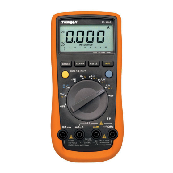
IMPORTANT SAFETY INFORMATION Please read these instructions carefully before use and retain for future reference. This instrument is designed and manufactured in compliance with: G84793, lEC61010-1, IEC61010-2-030 CAT III 1000V & CAT IV 600V, Pollution Degree 2 and Double Insulation standards. •...
K-type temperature probe (72-10405 & 72-2610 only) • 9V battery (installed) • RS232 PC interface cable FUNCTIONS LCD Display FUNCTION buttons BLUE button Range selector Input terminals DC VOLTAGE 72-2605 AND 72-10405 Input Fixed value Range Resolution 72-2605 Accuracy 72-10405 Impedance input 40mV 0.01mV ±(0.8%+3) Around Ω...
Page 4
>3000M 2.2V 0.0001V 1000V DC 0.001V ±(0.1%+2) 750V AC Ω Around 10M 220V 0.01V 1000V 0.1V ±(0.1%+5) AC VOLTAGE 72-2605 and 72-10405 Input Fixed value Range Resolution 72-2605 Accuracy 72-10405 Impedance input 40mV 0.01mV ±(1.2%+5) Around Ω >3000M 400mV 0.1mV ±(1.2%+5)
Page 5
DC CURRENT 72-2605 and 72-10405 Range Resolution Accuracy Overload Protection 400μA 0.1μA ±(1.0%+2) 4000μA 1μA Fuse 1 F600mA H 1000V 6.35 dia x 31.8mm 40mA 0.01mA ±(1.2%+3) 400mA 0.1mA 0.001A Fuse 2 F10A H 1000V ±(1.5%+3) 10.3 dia x 38.1mm 0.01A...
Page 6
AC CURRENT 72-2605 and 72-10405 Range Resolution Accuracy Overload Protection 400μA 0.1μA ±(1.2%+5) 4000μA 1μA Fuse 1 F600mA H 1000V 6.35 dia x 31.8mm 40mA 0.01mA ±(1.5%+5) 400mA 0.1mA 0.001A Fuse 2 F10A H 1000V ±(2.0%+5) 10.3 dia x 38.1mm 0.01A...
Page 7
RESISTANCE 72-2605 and 72-10405 Range Resolution Accuracy Overload Protection 400Ω 0.1Ω ±(1.2%+2) 4kΩ 0.001kΩ 40kΩ 0.01kΩ ±(1.0%+2) 1000V DC 750V AC 400kΩ 0.1kΩ 4MΩ 0.001MΩ ±(1.2%+2) 40MΩ 0.01MΩ ±(1.5%+2) Note: When measuring below 2kΩ, apply REL▲ to ensure measurement accuracy.
Page 8
When measuring on line frequency or duty cycle under AC voltage and current measurement mote, the input amplitude and frequency response must satisfy the following requirement: • Input amplitude ≥range x 30%. • Frequency response: 72-2605 and 72-10405 ≤400Hz. 72-2610, 72-10410 and 72-10415 ≤1kHz.
72-2610/72-10410 750V AC 72-10415 0.01Ω • 72-2605, 72-10405, 72-2610, 72-10410: Open circuit voltage is around 0.45V. Broken circuit resistance value is around >35Ω the buzzer does not sound. Good circuit resistance value is ≤10Ω the buzzer sounds continuously. • 72-10415: Open circuit voltage is around -3V.
µA ~ DCA and ACA measurement mA ~ DCmA and ACmA measurement 10A ~ 10A DC and AC measurement Sensor test (72-2605 only) Power off Function Buttons Below table indicates the operation of the function buttons. Button Operation Light (72-2605, 72-10405 Press and hold for 2 sec to turn backlight on or off 72-2610 &...
Page 11
Display symbols Symbol Meaning Data hold is active. Sleep Mode indicator Indicates negative reading. Indicator for AC measurement Indicator for DC measurement The Meter is in the auto range mode in which the Meter AUTO automatically selects the range with the best resolution. MANU Indicator for manual ranging mode.
Page 12
• Press and hold RANGE for over 2 seconds to return to autoranging; the Meter buzzer will sound. MAX MIN button 72-2605,72-10405 and 72-2610, 72-10410 only • Press MAX MIN to start recording of maximum and minimum values. Steps the display through high (MAX) and low (MIN) readings.
Page 13
If the circuit impedance is less than or equal to 10kΩ, the error is negligible (0.1% or less). • For 72-2605 : When measuring mV, you must press RANGE manually to enter mV range. •...
• Connect the test lead in serial to the circuit to be tested. The measured value shows on the display. • 72-2605,72-10405 and 72-2610: displays effective value of sine wave (mean value response). • 72-10415: displays the true rms value.
REL to subtract this from the tested value. • Connect the test leads across the object being measured. • 72-2605, 72-10405, 72-2610 and 72-10415: is around 10nF 72-10415: is around 1nF. • Alternatively, use the included multi-purpose socket for measuring capacitors with leads or SMT capacitor.
When temperature measurement has been completed, disconnect the temperature probe from the object being measured, and remove the temperature probe from the input terminals of the Meter. Transistor hFE Measurement 72-2605 only • Set the rotary switch to hFE. •...
Page 17
EF Function 72-2605 only • Set the rotary switch to EF and remove any test leads from the input terminals. • Place the housing front part with marking toward the source of EF. • There will be three types of displays: •...
Battery Type 9V NEDA 1604 or 6F22 or 006P Range Auto or manual Polarity Auto Measurement speed Updates 2-3 times/second Analogue bar graph 72-2605 and 72-2610 72-10415 72-10405 41 segments, 61 segments, 46 segments, max reading max reading max reading...
BATTERY REPLACEMENT Warning: Only replace the battery after the test leads are removed and the power is turned off. To replace the battery, • Remove the screw from the tilt stand and the battery cover and separate the battery cover and the tilt stand from the case bottom.
Page 20
INFORMATION ON WASTE DISPOSAL FOR CONSUMERS OF ELECTRICAL & ELECTRONIC EQUIPMENT These symbols indicate that separate collection of Waste Electrical and Electronic Equipment (WEEE) or waste batteries is required. Do not dispose of these items with general household waste. Separate for the treatment, recovery and recycling of the materials used. Waste batteries can be returned to any waste battery recycling point which are provided by most battery retailers.
Need help?
Do you have a question about the 72-2605 and is the answer not in the manual?
Questions and answers