
Related Manuals for Emerson Daniel Series


Summary of Contents for Emerson Daniel Series
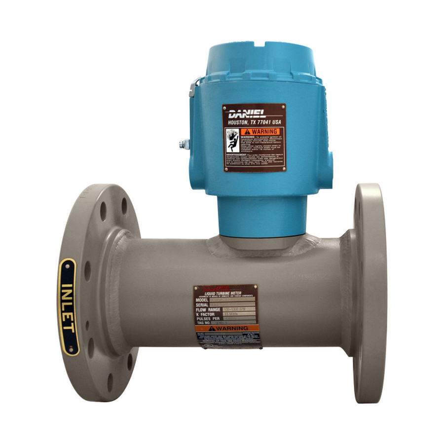
- Page 1 User manual P/N 3-9008-515, Rev AF March 2019 ™ Daniel Series 1500 Liquid Turbine Meter NPS 3 through 24...
- Page 3 Email • Customer Service: DanielCST.Support@Emerson.com • Customer Support: Daniel.TechnicalSupport@Emerson.com • Field Lifecycle Services: Tech.Service@Emerson.com • Asia-Pacific: danielap.support@emerson.com • Europe: danielEMA.cst@emerson.com Return Material Authorization (RMA) A Return Material Authorization (RMA) number must be obtained prior to returning any equipment for any reason. Access and fill in the RMA form for Daniel products clicking on the link below.
- Page 4 Signal words and symbols Pay special attention to the following signal words, safety alert symbols and statements: Safety alert symbol This is a safety alert symbol. It is used to alert you to potential physical injury hazards. Obey all safety messages that follow this symbol to avoid possible injury or death.
- Page 5 • Verify that this is the correct instruction manual for your Daniel product. If this is not the correct documentation, contact Daniel at 1-713-827-6314. You may also download the correct manual from: https://www.emerson.com/en-us/automation/ daniel. • Save this instruction manual for future reference.
- Page 6 • Verify that this is the correct instruction manual for your Daniel product. If this is not the correct documentation, contact Daniel at 1-713-827-6314. You may also download the correct manual from: https://www.emerson.com/en-us/automation/ daniel. • Read and understand all instructions and operating procedures for this product.
- Page 7 Notice THE CONTENTS OF THIS PUBLICATION ARE PRESENTED FOR INFORMATIONAL PURPOSES ONLY, AND WHILE EVERY EFFORT HAS BEEN MADE TO ENSURE THEIR ACCURACY, THEY ARE NOT TO BE CONSTRUED AS WARRANTIES OR GUARANTEES, EXPRESSED OR IMPLIED, REGARDING THE PRODUCTS OR SERVICES DESCRIBED HEREIN OR THEIR USE OR APPLICABILITY. ALL SALES ARE GOVERNED BY DANIEL'S TERMS AND CONDITIONS, WHICH ARE AVAILABLE UPON REQUEST.
- Page 8 Warranty and Limitations 1. LIMITED WARRANTY: Subject to the limitations contained in Section 2 herein, Daniel Measurement & Control, Inc. (“Daniel”) warrants that the licensed firmware embodied in the Goods will execute the programming instructions provided by Daniel, and that the Goods manufactured by Daniel will be free from defects in materials or workmanship under normal use and care and Services will be performed by trained personnel using proper equipment and instrumentation for the particular Service provided.
-
Page 9: Table Of Contents
User manual Contents P/N 3-9008-515 March 2019 Contents Part I Plan Chapter 1 Introduction.........................13 1.1 Purpose of this manual........................13 1.2 Description of the Series 1500 Liquid Turbine Meter (LTM)............. 13 1.3 Agency certifications for the Series 1500 LTM.................40 Chapter 2 Operating conditions and specifications...............41 2.1 Operating conditions for the liquid turbine meter................ - Page 10 Chapter 11 Spare parts.........................101 11.1 Recommended spare parts......................101 Chapter 12 Decommission the turbine meter................103 12.1 Shut down the turbine meter..................... 103 12.2 Turbine meter disassembly/assembly..................103 12.3 Shipment of the meter....................... 104 Daniel Series 1500 Liquid Turbine Meter, NPS 3-24...
-
Page 11: Part I Plan
User manual Plan P/N 3-9008-515 March 2019 Part I Plan User manual... - Page 12 Plan User manual March 2019 P/N 3-9008-515 Daniel Series 1500 Liquid Turbine Meter, NPS 3-24...
-
Page 13: Chapter 1 Introduction
1.2.1 General features of the turbine meter The Daniel Series 1500 Liquid Turbine Meter (LTM) is a volumetric flow metering and transmitting device used for accurate measurement of crude oil hydrocarbons and other related process fluids. The design allows high operational flow rates, extended flow ranges and sustained performance capability. - Page 14 The results may be displayed as pulse-counts or standard engineering units, such as gallons, liters, barrels, etc. Daniel Series 1500 Liquid Turbine Meter, NPS 3-24...
- Page 15 P/N 3-9008-515 March 2019 • All Daniel Series 1500 Liquid Turbine Meters have, as standard, the LME which is fitted with two pickoffs and a dual channel preamplifier. • The pickoff mountings are oriented so that the outputs from the pickups are 90º...
- Page 16 Introduction User manual March 2019 P/N 3-9008-515 LME assembly - Standard enclosure Figure 1-1: Part identification for a standard enclosure Daniel Series 1500 Liquid Turbine Meter, NPS 3-24...
- Page 17 User manual Introduction P/N 3-9008-515 March 2019 Table 1-1: Part description for a standard enclosure Item Description Part number Quantity number required End cap solid 1-360-00-025 Electronics enclosure 899-10-110-60 Plug pipe hex socket 154717-019 Grounding clamp B18934-004 Mounting bracket 899-10-230-50 Socket head screw 899-10-230-52 Warning tag-Hazard...
- Page 18 Introduction User manual March 2019 P/N 3-9008-515 LME assembly - Internal Totalizer Figure 1-2: Part identification for the LME with Internal Totalizer Daniel Series 1500 Liquid Turbine Meter, NPS 3-24...
- Page 19 User manual Introduction P/N 3-9008-515 March 2019 Table 1-2: Part description for the LME with Internal Totalizer Item Description Part number Quantity number required Cover (SS/ALUM) 899-10-230-60/70 Electronics enclosure (SS/ALUM) 899-10-110-60/70 Plug pipe hex socket 154717-019 Grounding cap B18934-004 Mounting bracket 899-10-230-50 Socket head screw 899-10-230-52...
- Page 20 Introduction User manual March 2019 P/N 3-9008-515 LME assembly - with Two Preamps Figure 1-3: Part identification Two preamps configuration Daniel Series 1500 Liquid Turbine Meter, NPS 3-24...
- Page 21 User manual Introduction P/N 3-9008-515 March 2019 Table 1-3: Part description for the LME with Two Preamps configuration Item Description Part number Quantity number required Cover (SS/ALUM) 899-10-230-60/70 Electronics enclosure (SS/ALUM) 899-10-230-60/70 Plug pipe hex socket 154717-019 Grounding cap B18934-004 Mounting bracket 899-10-230-50 Socket head screw...
- Page 22 Introduction User manual March 2019 P/N 3-9008-515 LME assembly - High temperature Figure 1-4: Part identification for a high temperature enclosure Daniel Series 1500 Liquid Turbine Meter, NPS 3-24...
- Page 23 User manual Introduction P/N 3-9008-515 March 2019 Table 1-4: Part description for a high temperature enclosure Item Description Part number Quantity number required End cap solid 1-360-00-25 Electronics enclosure 899-10-110-60 Plug pipe hex socket 154717-019 Grounding clamp B18934-004 Mounting bracket 899-10-230-50 Socket head screw 899-10-230-52...
- Page 24 Introduction User manual March 2019 P/N 3-9008-515 RME assembly - Pipe mount Figure 1-5: Part identification for an RME assembly - Pipe mount Daniel Series 1500 Liquid Turbine Meter, NPS 3-24...
- Page 25 User manual Introduction P/N 3-9008-515 March 2019 Table 1-5: Part description for an RME assembly - Pipe mount Item Description Part number Quantity number required End cap solid 1-360-00-025 Electronics enclosure 899-10-110-60 Plug pipe hex socket 154717-019 Grounding clamp B18934-004 Mounting bracket 899-10-230-50 Socket head screw...
- Page 26 Introduction User manual March 2019 P/N 3-9008-515 RME assembly - Wall mount Figure 1-6: Part identification for an RME assembly - Wall mount Daniel Series 1500 Liquid Turbine Meter, NPS 3-24...
- Page 27 User manual Introduction P/N 3-9008-515 March 2019 Table 1-6: Part description for an RME assembly - Wall mount Item Description Part number Quantity number required End cap solid 1-360-00-025 Electronics enclosure 899-10-110-60 Plug pipe hex socket 154717-019 Grounding clamp B18934-004 Mounting bracket 899-10-230-50 Socket head screw...
- Page 28 Meter housing internal components - NPS 3 through 8 - Unidirectional The figure below identifies and describes the NPS 3 through 8 unidirectional meter housing components. Figure 1-7: Part identification for an NPS 3 through 8 unidirectional (blade or rimmed) LTM Daniel Series 1500 Liquid Turbine Meter, NPS 3-24...
- Page 29 User manual Introduction P/N 3-9008-515 March 2019 Table 1-7: Part description for an NPS 3 unidirectional LTM Item Description Part number for Part number for Quantity number material 304 SS material 316 SS required O-ring 1500093-022 1500093-022 Meter housing Consult factory Consult factory Pickoff 899-00-201-00...
- Page 30 Table 1-10: Part description for an NPS 8 unidirectional LTM Item Description Part number for Part number for Quantity number material 304 SS material 316 SS required O-ring 15000093-022 15000093-022 Meter housing Consult factory Consult factory Pickoff 899-00-201-00 899-00-201-00 Daniel Series 1500 Liquid Turbine Meter, NPS 3-24...
- Page 31 User manual Introduction P/N 3-9008-515 March 2019 Table 1-10: Part description for an NPS 8 unidirectional LTM (continued) Item Description Part number for Part number for Quantity number material 304 SS material 316 SS required Anti-rotation bracket clamp 899-10-230-66 899-10-230-66 Thrust washer 1-504-05-118 1-504-05-118...
- Page 32 Meter housing internal components - NPS 10 through 24 - Unidirectional The figure below identifies and describes the NPS 10 through 24 unidirectional meter housing components. Figure 1-8: Part identification for an NPS 10 through 24 unidirectional (rimmed) LTM Daniel Series 1500 Liquid Turbine Meter, NPS 3-24...
- Page 33 User manual Introduction P/N 3-9008-515 March 2019 Table 1-11: Part description for an NPS 10 unidirectional LTM Item Description Part number for Part number for Quantity number material 304 SS material 316 SS required O-ring 1500093-022 1500093-022 Meter housing Consult factory Consult factory Pickoff 899-00-201-00...
- Page 34 1-504-05-657 1-504-05-657 1-561-76-088 1-561-76-088 Upstream cone 1-307-10-491 1-307-10-494 Downstream cone 1-307-10-591 1-307-10-594 Housing insert 1-307-03-009 1-307-03-029 Hanger blades 1-307-10-770 1-307-10-771 Cotter pin 1-562-05-656 1-562-05-656 Hanger hub 1-307-10-696 1-307-10-697 Rotor assembly 1-307-11-686 1-307-11-687 Daniel Series 1500 Liquid Turbine Meter, NPS 3-24...
- Page 35 User manual Introduction P/N 3-9008-515 March 2019 Table 1-15: Part description for an NPS 20 unidirectional LTM Item Description Part number for Quantity number material 304 SS required O-ring 1500093-022 Meter housing Consult factory Pickoff 899-00-201-00 Anti-rotation bracket clamp 899-10-230-66 Thrust washer 1-504-05-124 Shaft...
- Page 36 Table 1-16: Part description for an NPS 24 unidirectional LTM (continued) Item Description Part number for Quantity number material 304 SS required Rotor assembly 1-307-11-701 Note For 316 SS material part numbers, consult the factory. Daniel Series 1500 Liquid Turbine Meter, NPS 3-24...
- Page 37 User manual Introduction P/N 3-9008-515 March 2019 Meter housing internal components - NPS 3 through 8 - Bidirectional The figure below identifies and describes the NPS 3 through 8 bidirectional meter housing components. Figure 1-9: Part identification for an NPS 3 through 8 bidirectional (blade or rimmed) User manual...
- Page 38 1-504-05-627 1-504-05-627 Bladed rotor 1-307-11-300 1-307-11-301 1-561-76-155 1-561-76-155 Upstream cone-rimmed 1-307-10-440 1-307-10-444 Upstream cone-bladed 1-307-10-442 1-307-10-443 Housing insert 1-307-03-001 1-307-03-021 Hanger blades 1-307-10-740 1-307-10-741 Hanger hub 1-307-10-640 1-307-10-641 Rimmed rotor 1-307-11-302 1-307-11-303 Daniel Series 1500 Liquid Turbine Meter, NPS 3-24...
- Page 39 User manual Introduction P/N 3-9008-515 March 2019 Table 1-19: Part description for an NPS 6 bidirectional LTM Item Description Part number for Part number for Quantity number material 304 SS material 316 SS required O-ring 1500093-022 1500093-022 Meter housing Consult factory Consult factory Pickoff 899-00-201-00...
-
Page 40: Agency Certifications For The Series 1500 Ltm
Rev. 7 Pressure equipment CE 60685 (2014/68/EU Module H1) Metrology NMi TC7573 TC7573 Rev. 4 INMETRO (Brazil) UL-BR 16.0354X Rev. 2016 Ambient temperature -40 ºC to 60 ºC (-40 ºF to 140 ºF) Daniel Series 1500 Liquid Turbine Meter, NPS 3-24... -
Page 41: Operating Conditions And Specifications
-40 ºC to 204 ºC (-40 ºF to 400 ºF) (Stainless steel flanges) Fluid static pressure The maximum working pressure for the Daniel Series 1500 Liquid Turbine Meter is based on the temperature/ pressure rating of the ANSI B16.5 flanges. For maximum working pressures at intermediate temperatures refer to ANSI B16.5. - Page 42 Corrosive service Select the material compatible with specific processes and atmospheric environments. Implement a periodic inspection and maintenance program to ensure that pressure-retaining components are free from corrosion and erosion. Daniel Series 1500 Liquid Turbine Meter, NPS 3-24...
- Page 43 User manual Operating conditions and specifications P/N 3-9008-515 March 2019 Table 2-2: Environmental conditions (continued) Parameter type Description Low and freezing temperatures Low specific gravities or high viscosities reduce the flow range of the turbine meter. Refer to Operating parameters for the LTM for more information.
- Page 44 (psia), gauge pressure plus atmospheric pressure. illustrates the effects of back pressure. Insufficient back pressure leads to measurement inaccuracy. The resulting flashing and cavitation is extremely damaging to the flow meter and pipe work. Daniel Series 1500 Liquid Turbine Meter, NPS 3-24...
- Page 45 User manual Operating conditions and specifications P/N 3-9008-515 March 2019 Figure 2-1: Effects of back pressure Back pressure calculation ≥ 2Δp + 1.25p Equation 2-2: Back pressure calculation Minimum back pressure, pounds per square inch gauge (psig) Δp Pressure drop through the meter at the maximum operating flow rate for the liquid being measured, pounds per square inch (psi).
-
Page 46: Specifications For The Ltm
Temperature range: -40 ºC to 85 ºC (-40 ºF to 185 ºF) Outputs Powered pulse output: • Type: Square wave • Frequency range: 0 to 5 kHz • Amplitude: 0 to 5 V • 1000 Ohm internal pull-ups, 20 mA, max. Daniel Series 1500 Liquid Turbine Meter, NPS 3-24... - Page 47 User manual Operating conditions and specifications P/N 3-9008-515 March 2019 Table 2-3: 2818 Dual channel preamplifier performance (continued) Parameter type Description Variable voltage output: • Type: Square wave • Frequency range: 0 to 5 kHz • Amplitude: 0 to Supply voltage •...
- Page 48 (18AWG), or equivalent. • Connect both shields to earth ground at one end of the cables and insulate the shields at the other end. • The LME housing should be at earth ground. Daniel Series 1500 Liquid Turbine Meter, NPS 3-24...
- Page 49 User manual Operating conditions and specifications P/N 3-9008-515 March 2019 Table 2-7: 2818 Dual channel preamplifier configuration Plug component designator Terminal connections Description TB1 - Customer connection +10 to 30 Vdc Common Common Channel A output Channel B output TTL out A TTL out B TB2 - Channel A pickoff (1) White...
- Page 50 Other types of flange connections are available per customer request. For other ANSI ratings or flanges consult the factory engineers. For maximum working pressures at intermediate temperatures refer to ANSI B16.5. Daniel Series 1500 Liquid Turbine Meter, NPS 3-24...
- Page 51 User manual Operating conditions and specifications P/N 3-9008-515 March 2019 WARNING HIGH PRESSURE HAZARD Choose the appropriate size and material of the flange for their piping requirements. Choosing an incorrect flange may cause a pressure leak, resulting in death or serious injury.
- Page 52 914.4 457.2 469.1 1016 494.5 1219 545.3 Table 2-12: Flow meter and flow straightening section dimensions for the Series 1500 LTM NPS 3-24 Size Inches Inches Inches 1397.0 1016 1828.8 1524 2641.6 Daniel Series 1500 Liquid Turbine Meter, NPS 3-24...
- Page 53 User manual Operating conditions and specifications P/N 3-9008-515 March 2019 Table 2-12: Flow meter and flow straightening section dimensions for the Series 1500 LTM NPS 3-24 (continued) Size Inches Inches Inches 2032 1016 3454.4 2540 1270 4318.0 3048 1524 5181.6 4064 2032 6908.8...
- Page 54 Operating conditions and specifications User manual March 2019 P/N 3-9008-515 Daniel Series 1500 Liquid Turbine Meter, NPS 3-24...
-
Page 55: Turbine Meter Handling
User manual Turbine meter handling P/N 3-9008-515 March 2019 Turbine meter handling Receive the turbine meter WARNING EQUIPMENT HANDLING AND OPERATING HAZARD Wear personal protective equipment appropriate to the situation when working with the turbine meter. Adhere to all safety standards and best practices for operating the equipment. - Page 56 Do not remove nameplates or labels. Doing so will void the turbine meter warranty. Stacking When stacking equipment, follow all safety standards, taking into account the type of box used, the maximum height of the equipment, the maximum number of boxes stacked, etc. Daniel Series 1500 Liquid Turbine Meter, NPS 3-24...
-
Page 57: Prepare The Turbine Meter For Use
User manual Prepare the turbine meter for use P/N 3-9008-515 March 2019 Prepare the turbine meter for use Lifting conditions WARNING CRUSHING HAZARD During turbine meter installation or removal, always place the unit on a stable platform or surface that supports its assembled weight. Failure to comply could allow the turbine meter to roll, resulting in death, serious injury or equipment damage. -
Page 58: Lifting Requirements For Personnel
Minimum clearances for installation, operation and maintenance for the assemble weight. The following instructions provide general guidelines using lifting slings only on the Daniel turbine meter. Use appropriately rated lifting slings when lifting the turbine meter. Daniel Series 1500 Liquid Turbine Meter, NPS 3-24... - Page 59 User manual Prepare the turbine meter for use P/N 3-9008-515 March 2019 Safety precautions using appropriately rated lifting slings When lifting a liquid turbine meter by itself, Daniel recommends using lifting slings appropriately positioned at designated areas of the turbine meter. WARNING LIFTING HAZARD The lifting instructions are for installation and removal of the Daniel Liquid Turbine...
- Page 60 Doing this may cause injury and/or damage the equipment. • Never apply shock loads to the turbine meter. Always lift the turbine meter gradually. If shock loading occurs, inspect the slings per manufacturer's recommendations prior to further use. Daniel Series 1500 Liquid Turbine Meter, NPS 3-24...
-
Page 61: Configuration Of The Turbine Meter
User manual Prepare the turbine meter for use P/N 3-9008-515 March 2019 Configuration of the turbine meter The Daniel factory configures the turbine meter internal components. Inspect the internal components before installation. 4.3.1 Orientation and position of the turbine meter Flow direction Turbine meters can be used for uni-directional or bi-directional flows. - Page 62 Comply with local government regulations and company requirements. Important Ensure that piping or other attachments connected to the turbine meter are not under stress. Important Provide fire prevention measures and equipment per local regulations. Daniel Series 1500 Liquid Turbine Meter, NPS 3-24...
- Page 63 User manual Prepare the turbine meter for use P/N 3-9008-515 March 2019 4.3.3 Calibration options for the turbine meter Daniel offers a standard six-point calibration (from 10% to 100%); or can provide other customer requested calibration data. Table 4-2: Standard calibration for a Daniel Liquid Turbine Meter Calibration type Description Linearity...
- Page 64 LME as the primary ground. A secondary ground is located outside of the LME. Refer to Figure 4-4 Figure 4-5. Digital grounds should never be connected to chassis ground. Daniel Series 1500 Liquid Turbine Meter, NPS 3-24...
- Page 65 User manual Prepare the turbine meter for use P/N 3-9008-515 March 2019 Figure 4-4: External ground lug A. External ground lug Figure 4-5: Internal ground lug A. Internal ground lug Important Use the internal grounding terminal as the primary equipment ground. The external terminal is only a supplemental bonding connection where local authorities permit or require such a connection.
- Page 66 Table 4-4. Table 4-4: Installation dimensions for the RME Device Transmission distance Pickoff to RME 6.1 meters (20 ft.) maximum from RME dual channel Preamplifier to receiver 1525 meters (5,000 ft.) maximum Daniel Series 1500 Liquid Turbine Meter, NPS 3-24...
- Page 67 User manual Prepare the turbine meter for use P/N 3-9008-515 March 2019 Figure 4-6: Typical installation for the RME 4.3.8 Install the security seal Security seals protect the integrity of the turbine meter metrology and prevent preamplifier and pickoff tampering. Follow the steps below to seal the electronics enclosure of the Daniel 1500 LTM after commissioning.
- Page 68 (maximum wire diameter 2.0 mm, .078 inch). 3. Adjust the security wire, removing all slack and thread into the lead seal. 4. Cut the ends of the wire to remove any excess wire. Daniel Series 1500 Liquid Turbine Meter, NPS 3-24...
-
Page 69: Part Ii Install
User manual Install P/N 3-9008-515 March 2019 Part II Install User manual... - Page 70 Install User manual March 2019 P/N 3-9008-515 Daniel Series 1500 Liquid Turbine Meter, NPS 3-24...
-
Page 71: Chapter 5 Installation Prerequisites
User manual Installation prerequisites P/N 3-9008-515 March 2019 Installation prerequisites Pre-start checks Procedure 1. Inspect all electrical connections to ensure compliance to electrical codes and safety regulations. 2. Inspect all bolts used to secure the turbine meter in line to ensure that correct mounting procedures have been followed and that flange connections are leak- free. - Page 72 Installation prerequisites User manual March 2019 P/N 3-9008-515 Daniel Series 1500 Liquid Turbine Meter, NPS 3-24...
-
Page 73: Chapter 6 Installation Procedure
User manual Installation procedure P/N 3-9008-515 March 2019 Installation procedure Cathodic protection Table 6-1: Standards for cathodic protection Material Daniel standard cathodic protection Carbon steel Zinc Phosphate Consult the factory for other protection. Mechanical components assembly Install the meter housing (e.g., flanges) onto the pipeline. The meter housing internal components are assembled by the factory. -
Page 74: Assemble The Electronic Components
Failure to comply may result in death or serious injury. Procedure 1. Remove the security seal wire. 2. Remove the security latch using the 3 mm Allen key. Daniel Series 1500 Liquid Turbine Meter, NPS 3-24... - Page 75 User manual Installation procedure P/N 3-9008-515 March 2019 Important The security latch prevents the removal of the LME cover in a flameproof environment. 3. Unscrew the end cap and remove it from the housing. 4. Unplug one or two ¾-14 NPT ports (as required) and install the conduit (provided by the customer) to the enclosure and tighten.
- Page 76 Installation procedure User manual March 2019 P/N 3-9008-515 Daniel Series 1500 Liquid Turbine Meter, NPS 3-24...
-
Page 77: Chapter 7 Testing
User manual Testing P/N 3-9008-515 March 2019 Testing Test the turbine meter 7.1.1 Commission the turbine meter After installation, commission the turbine meter to ensure that the equipment is working properly. Procedure 1. Inspect all electrical connections to ensure compliance with electrical codes and safety regulations. - Page 78 Testing User manual March 2019 P/N 3-9008-515 Daniel Series 1500 Liquid Turbine Meter, NPS 3-24...
-
Page 79: Part Iii Operate
User manual Operate P/N 3-9008-515 March 2019 Part III Operate User manual... - Page 80 Operate User manual March 2019 P/N 3-9008-515 Daniel Series 1500 Liquid Turbine Meter, NPS 3-24...
-
Page 81: Chapter 8 Operation Parameters
Operation parameters Operation overview The Daniel Series 1500 LTM is a volumetric flow measuring and transmitting device that produces an output signal proportional to the rate-of-flow of the liquid being measured. The primary output is a single or dual high resolution signal that is amplified and shaped by an integral preamplifier mounted within an explosion-proof housing. -
Page 82: Lme Remote Operation
This wave pulse can be fed directly to remote totalizing counters, digital readout devices, presets, or control instrumentation. NOTICE Inspect all electrical connections to ensure compliance to electrical codes and safety regulations. Daniel Series 1500 Liquid Turbine Meter, NPS 3-24... -
Page 83: Part Iv Maintain
User manual Maintain P/N 3-9008-515 March 2019 Part IV Maintain User manual... - Page 84 Maintain User manual March 2019 P/N 3-9008-515 Daniel Series 1500 Liquid Turbine Meter, NPS 3-24...
-
Page 85: Chapter 9 Planned Maintenance
User manual Planned maintenance P/N 3-9008-515 March 2019 Planned maintenance Maintenance considerations Read and understand all instructions and operating procedures before performing maintenance procedure, internal component inspections or field requirement changes. To ensure safe and accurate performance, only informed and trained personnel should install, operate, repair and maintain this product. -
Page 86: Prepare For Mechanical Disassembly
6. Disconnect conduit connections to the turbine meter. 7. Remove turbine meter from line. Refer to Lifting equipment Lifting conditions, Lifting requirements for personnel, and Safety precautions using appropriately rated lifting slings for instructions on lifting the turbine meter. Daniel Series 1500 Liquid Turbine Meter, NPS 3-24... - Page 87 User manual Planned maintenance P/N 3-9008-515 March 2019 9.3.1 Disassemble internal meter housing components - NPS 3 through 24 Procedure 1. Remove the downstream shaft nut, simultaneously holding the upstream shaft nut to prevent the shaft from turning. Figure 9-1: Downstream shaft nut removal Important The shaft nut can only be reused up to five times.
- Page 88 4. Remove the rotor from the shaft. Depending on the turbine meter option, the rotor could be just a blade type or a rim type. The rim is not removable from the rotor assembly. Daniel Series 1500 Liquid Turbine Meter, NPS 3-24...
- Page 89 User manual Planned maintenance P/N 3-9008-515 March 2019 Figure 9-4: Rotor removal 5. Remove the journal bearing. Figure 9-5: Journal bearing removal 6. Remove the upstream cone from the shaft. The thrust washer should remain in the cone. User manual...
- Page 90 Insert the shaft from the downstream end and push the shaft against the pin. c) Tap the shaft lightly to free the downstream hanger assembly. Figure 9-7: Upstream hanger assembly removal Daniel Series 1500 Liquid Turbine Meter, NPS 3-24...
-
Page 91: Mechanical Assembly
User manual Planned maintenance P/N 3-9008-515 March 2019 Mechanical assembly Protection for rotor blades from rough handling as blade position is critical to turbine meter performance. Use appropriate torque values to reinstall the shaft nut and to avoid equipment damage or inaccurate turbine meter operation. - Page 92 3. Insert the upstream cone to the shaft. The thrust washer should remain in the cone. Figure 9-9: Upstream cone installation 4. Insert the journal bearing in to the rotor assembly. Daniel Series 1500 Liquid Turbine Meter, NPS 3-24...
- Page 93 User manual Planned maintenance P/N 3-9008-515 March 2019 Figure 9-10: Journal bearing installation 5. Install the rotor to the shaft. Figure 9-11: Rotor installation 6. Install the downstream cone to the shaft. The thrust washer should remain in the cone. User manual...
- Page 94 7. Install the downstream hanger assembly to the shaft. Figure 9-13: Downstream hanger assembly installation 8. Install the downstream shaft nut, simultaneously holding the upstream shaft nut to prevent the shaft from turning. Daniel Series 1500 Liquid Turbine Meter, NPS 3-24...
-
Page 95: Electronics Enclosure Disassembly
User manual Planned maintenance P/N 3-9008-515 March 2019 Figure 9-14: Downstream shaft nut installation Important The shaft nut can only be reused up to five times. Replace as needed. Electronics enclosure disassembly WARNING ELECTRONIC HAZARD Power off the electronics after every use. Servicing the turbine meter while powered may result in death or serious injury. -
Page 96: Electronics Enclosure Assembly
(1.030 in), radial length of 3.18 mm (0.125 in), and a clearance of 0.07 mm (0.0028 in). 9.6.1 Assemble the LME/RME - Standard enclosure Procedure 1. Install the O-ring on the pad. Daniel Series 1500 Liquid Turbine Meter, NPS 3-24... -
Page 97: Replace The Preamplifier
User manual Planned maintenance P/N 3-9008-515 March 2019 2. Install the housing on the turbine meter body or remote mounting pad. Use four screws with a torque value of 74.5 Nm (55 lbs-ft) (Capacity to be installed: each at 90º). 3. -
Page 98: Planned Maintenance Tasks
A careful review of turbine meter proving history, such as turbine meter factor control charts, can reveal potential problems with turbine meter measurements. Examples include bearing drag due to wear or an increased internal cross-sectional area due to erosion. Daniel Series 1500 Liquid Turbine Meter, NPS 3-24... -
Page 99: Chapter 10 Corrective Maintenance
User manual Corrective maintenance P/N 3-9008-515 March 2019 Corrective maintenance 10.1 Turbine meter troubleshooting Use the table below to troubleshoot the turbine meter. Contact the nearest Daniel Measurement and Control Sales or Service office for repairs. It is important that servicing be performed by trained and qualified service personnel. - Page 100 Corrective maintenance User manual March 2019 P/N 3-9008-515 4. Ensure that the supply voltage to the preamplifier is within the 10-30 VDC range. Daniel Series 1500 Liquid Turbine Meter, NPS 3-24...
-
Page 101: Chapter 11 Spare Parts
User manual Spare parts P/N 3-9008-515 March 2019 Spare parts 11.1 Recommended spare parts The figure below identifies the spare parts for an LME assembly. Figure 11-1: Part identification for a standard enclosure Table 11-1: Recommended spare parts for an LME assembly (standard) Item number Description Part number... - Page 102 RME assembly - Wall mount. Order spare parts Contact Daniel Customer Service and provide the following information when ordering spare parts: • Turbine meter serial number • Part number • Part description • Quantity Daniel Series 1500 Liquid Turbine Meter, NPS 3-24...
-
Page 103: Decommission The Turbine Meter
User manual Decommission the turbine meter P/N 3-9008-515 March 2019 Decommission the turbine meter 12.1 Shut down the turbine meter Follow the steps below to shut down and disassemble the turbine meter for storage or shipment. WARNING PRESSURE HAZARD The turbine meter is subject to pressurized fluids. Depressurize the turbine meter before disassembly. -
Page 104: Shipment Of The Meter
Decommission the turbine meter User manual March 2019 P/N 3-9008-515 12.3 Shipment of the meter Refer to the Daniel Customer Service information in the preface of this document. Daniel Series 1500 Liquid Turbine Meter, NPS 3-24... - Page 105 User manual P/N 3-9008-515 March 2019 User manual...
- Page 106 Daniel Measurement and Control, Inc. ("Daniel") is an Emerson Automation Solutions business unit. The Daniel name and logo are trademarks of Daniel Industries, Inc. The Emerson logo is a trademark and service mark of Emerson Electric Co. All other trademarks are the property of their respective...
Need help?
Do you have a question about the Daniel Series and is the answer not in the manual?
Questions and answers