Table of Contents
Advertisement
Quick Links
Advertisement
Table of Contents

Subscribe to Our Youtube Channel
Related Manuals for Manitowoc CD15


Summary of Contents for Manitowoc CD15
- Page 1 CD15 Operator Manual 8905...
- Page 2 THIS PAGE BLANK...
- Page 3 DANGER An untrained operator subjects himself and others to death or serious injury. Do not operate this crane unless: Manitowoc is not • You are trained in the safe operation of this crane. responsible for qualifying personnel.
- Page 4 WARNING California Proposition 65 Breathing diesel engine exhaust exposes you to chemicals known to the State of California to cause cancer and birth defects or other reproductive harm. • Always start and operate the engine in a well- ventilated area. •...
-
Page 5: Table Of Contents
CD15 OPERATOR MANUAL TABLE OF CONTENTS See End of this Manual for Alphabetical Index SECTION 1 ........Introduction The Manual . - Page 6 TABLE OF CONTENTS CD15 OPERATOR MANUAL Transporting the Crane..........2-31 Travel Operation.
- Page 7 CD15 OPERATOR MANUAL TABLE OF CONTENTS Turning Clearances..........3-29 Crane Shutdown .
- Page 8 TABLE OF CONTENTS CD15 OPERATOR MANUAL Scheduled Maintenance ..........6-10 Daily (Walk-around) Inspection .
-
Page 9: The Manual
Disclaimer ....... . 1-2 THE MANUAL This operator’s manual provides the information you need to correctly operate and maintain the CD15 crane. NOTE: Before you operate the crane, carefully read this... - Page 10 INTRODUCTION CD15 OPERATOR MANUAL returned to the engine manufacturer for full warranty coverage. Published 3-30-2018, CTRL 636-05...
-
Page 11: Disclaimer
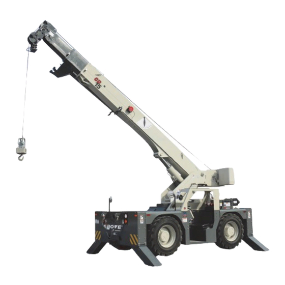
New Owners Dealer If you are the new owner of a Grove crane, please register it with Manitowoc Crane Care so we have the ability to contact Manitowoc and our Dealer Network want to ensure your you if the need arises. - Page 12 INTRODUCTION CD15 OPERATOR MANUAL 8905 Item Description Hook Block or Downhaul Weight Optional Jib (boom extension) Anti-Two-Block and RCL Device Pivoting Boom Head 3rd Boom Section (4th section optional) 2nd Boom Section 1st Boom Section Lift Cylinder Hoist (load) Counterweight (1-piece)
-
Page 13: Section 2
CD15 OPERATOR MANUAL SAFETY INFORMATION SECTION 2 SAFETY INFORMATION SECTION CONTENTS Safety Messages......2-1 Maintenance. -
Page 14: Safety Alert Symbol
Should the dealer not be immediately available, CAUTION contact should be made directly with Manitowoc Product Identifies hazards that could result in minor or moderate Safety at the address below. The crane must not be returned injury if the message is ignored. -
Page 15: Operator Qualifications
CD15 OPERATOR MANUAL SAFETY INFORMATION The Operator Manual supplied with and considered part of decals on the crane. Decals provide important instructions your crane must be read and completely understood by each and warnings and must be read prior to any operational or person responsible for assembly, disassembly, operation maintenance function. -
Page 16: Operational Aids
SAFETY INFORMATION CD15 OPERATOR MANUAL i m pa i r p h y s i c a l , v i s u a l a n d m e n ta l r e a c t i o n s , a n d additional signal person to furnish equivalent protection. -
Page 17: Working Area Limiter (If Equipped)
CD15 OPERATOR MANUAL SAFETY INFORMATION stressed and overloaded in which case the hoist rope may preventing this condition. An Anti-Two-Block System is fail allowing the load, block, etc. to free fall. intended to assist the operator in preventing dangerous two- block conditions. -
Page 18: Load Charts
SAFETY INFORMATION CD15 OPERATOR MANUAL Ensure all pins and floats are properly installed and outrigger must be properly extended and set to provide precise beams are properly extended before lifting on outriggers. On leveling of the crane. Tires must be clear of the ground models equipped with outriggers that can be pinned at the before lifting on outriggers. -
Page 19: Wind Forces
CD15 OPERATOR MANUAL SAFETY INFORMATION Be aware of the danger for people entering the working area. upon the direction from which the wind is blowing (e.g., wind Do not allow unnecessary personnel in the vicinity of the on the rear of the boom can result in decreased forward crane while operating. - Page 20 SAFETY INFORMATION CD15 OPERATOR MANUAL This 3-second wind gust is assumed to act on the entire NOTE: This condition is limited to operation with the main crane and the load. The wind effect on the load can be boom on fully extended outriggers only.
- Page 21 CD15 OPERATOR MANUAL SAFETY INFORMATION Simplified Method to Determine Maximum Permissible Wind Speed Determine 3-Second Gust 0.14 V(z) = [(z/10) + 0.4]v [m/s] Wind Speed at boom tip, 0.14 V(z) = [(z/33) + 0.4]v [mph] V(z) 13.4 m/s < V(z) < 20.1 m/s V(z) >...
- Page 22 SAFETY INFORMATION CD15 OPERATOR MANUAL Determination of 3-second wind gust speed at boom Size and Shape of the load: tip height: These rated capacities are also based on the assumption that the Wind Resistance Area of load, Awr is not more...
- Page 23 CD15 OPERATOR MANUAL SAFETY INFORMATION Calculation of Projected Wind Area (Ap) Wind Wind = 8 m = 24 m 25 ft 25 ft Wind Wind 10 ft 3 ft = 75 ft = 250 ft 10 ft 3 ft 8384-1...
- Page 24 SAFETY INFORMATION CD15 OPERATOR MANUAL Table 2-2 Wind Drag Coefficient Maximum Permissible Wind Speed If the wind resistant area of the load Awr is greater than (load) Shape the allowable wind resistant area Awr , the ratio can be (allow) used to determine a permissible wind speed V(z) for the load 1.1 to 2.0...
- Page 25 CD15 OPERATOR MANUAL SAFETY INFORMATION Rated Load Chart Example - Metric 8383-1 FIGURE 2-3 2-13 Published 3-30-2018, CTRL 636-05...
- Page 26 SAFETY INFORMATION CD15 OPERATOR MANUAL Table 2-4 Example-Capacity Reduction Factors for Wind Speed V(z) Greater than 13.4 m/s - Metric (Only for lifting with main boom on fully extended outriggers, with or without stowed extension) For wind speed V(z) (3-second gust speed at boom tip height) V(z) > 13.4 m/s ≤ 20.1 m/s, the Reduced Capacity...
- Page 27 CD15 OPERATOR MANUAL SAFETY INFORMATION At wind speeds greater than 13.4 m/s, it is not permissible to Load example 1.3a: lift a load greater than 12,040 kg, even if the wind resistance With large wind resistance area of the load Awr (load) area of the load is less than 14.45 m...
- Page 28 SAFETY INFORMATION CD15 OPERATOR MANUAL • Is the load to be lifted less than allowable load? Ratio = 1.37 8,000 kg ≤ 12,040 kg • Is Awr less than Awr (load) (allow) From Table 2-5, the maximum permissible wind speed at 19.83 m...
- Page 29 CD15 OPERATOR MANUAL SAFETY INFORMATION Rated Load Chart Example - Non-metric 8382-1 FIGURE 2-4 2-17 Published 3-30-2018, CTRL 636-05...
- Page 30 SAFETY INFORMATION CD15 OPERATOR MANUAL Table 2-6 Example-Capacity Reduction Factors for Wind Speed V(z) Greater than 30 mph - Non-metric (Only for lifting with main boom on fully extended outriggers, with or without stowed extension) For wind speed Vz (3-second gust speed at boom tip height) is greater > 30> mph ≤ 45 mph, the Reduced Capacity...
- Page 31 CD15 OPERATOR MANUAL SAFETY INFORMATION • Is Awr less than Awr (load) (allow) 108 ft ≤ 119 ft L i f t i n g L i m i t s a t w i n d s p e e d V ( z ) > 3 0 m p h Conclusion: This load is permissible to lift in wind speed up and ≤...
-
Page 32: Lifting Operations
SAFETY INFORMATION CD15 OPERATOR MANUAL Refer to the above Lifting Limits at wind speed V(z) injury could result from the crane tipping over or failing > 30 mph and ≤ 45 mph. Comparing the load and wind structurally from overload. -
Page 33: Counterweight
CD15 OPERATOR MANUAL SAFETY INFORMATION Counterweight • Maintain communication between all parties throughout the entire operation. If possible, provide approved radio On cranes equipped with removable counterweights, ensure equipment for voice communication between all parties the appropriate counterweight sections are properly installed engaged in the lift. -
Page 34: Electrocution Hazard
SAFETY INFORMATION CD15 OPERATOR MANUAL • The panel shall be lifted so that the hoist lines are in line United States federal law prohibits the use of cranes closer than 6 m (20 ft) to power sources with the crane. -
Page 35: Set-Up And Operation
CD15 OPERATOR MANUAL SAFETY INFORMATION Crane operation is dangerous when close to an energized entering into an unsafe distance from electrical power lines electrical power source. Exercise extreme caution and or equipment. prudent judgement. Operate slowly and cautiously when in Plan ahead and always plan a safe route before traveling the vicinity of power lines. -
Page 36: Electrical Contact
Should the dealer not be immediately located outside of the sensing area. Much reliance is placed available, contact Manitowoc Crane Care. The crane must upon you, the operator, in selecting and properly setting the not be returned to service until it is thoroughly inspected for sensitivity of these devices. -
Page 37: Grounding The Crane
CD15 OPERATOR MANUAL SAFETY INFORMATION Grounding the Crane The crane may become charged with static electricity. This may occur especially when using outrigger pads made of WARNING plastic or when the outrigger pads are packed with insulating Risk of accidents due to electric shock! material (e.g. -
Page 38: Environmental Protection
SAFETY INFORMATION CD15 OPERATOR MANUAL • A determination has been made that use of a crane to • NEVER allow anyone other than the operator to be on handle personnel is the least hazardous means to this crane while the machine is operating or traveling. -
Page 39: Service And Repairs
CD15 OPERATOR MANUAL SAFETY INFORMATION limiter and control lever lockout systems for all lifting Hydraulic Fluid: operations. • Do not use your hand or any part of your body to check Shut down the crane while making repairs or adjustments. -
Page 40: Lubrication
Always make daily inspections of the hoist rope, keeping in • Consult with Manitowoc Crane Care to determine if load mind that all hoist rope will eventually deteriorate to a point testing is required after a structural repair is performed. - Page 41 CD15 OPERATOR MANUAL SAFETY INFORMATION • Any kinking, bird caging, crushing, corrosion, or other safely used on the application. Inspection criteria, damage resulting in distortion of the rope structure. including number and location of broken wires, wear and elongation, have been established by OSHA, ANSI, •...
-
Page 42: Sheaves
SAFETY INFORMATION CD15 OPERATOR MANUAL • Follow proper instructions for removing rope from a reel. based only upon visible wire breaks may prove inadequate in predicting rope failure. The user of • Apply back tension to the storage/payoff reel of the new cast nylon sheaves is therefore cautioned that a rope to insure tight, even spooling onto the hoist drum. -
Page 43: General Maintenance
CD15 OPERATOR MANUAL SAFETY INFORMATION battery cable. For cranes with a Cummins engine using Ensure the crane is adequately secured to the transporting an engine ECM: vehicle. Ensure that the key switch has been off for 2 minutes. Do not use the dead end lug (1, Figure 2-8) on the boom nose for tying down the boom during transport. -
Page 44: Work Practices
SAFETY INFORMATION CD15 OPERATOR MANUAL ground, may create a bouncing effect that can result in loss Pick and carry on level surfaces only. of control. If bouncing occurs, reduce travel speed. Refer to the Operation Section for more detailed information on traveling on slopes. -
Page 45: Job Preparation
CD15 OPERATOR MANUAL SAFETY INFORMATION Working surface if slip-resistant material is missing or excessively worn. Operator shall be responsible for all operations under his/her Do not use the top of the boom as a walkway. direct control. When safety of an operation is in doubt, operator shall stop the crane’s functions in a controlled... -
Page 46: Lifting
SAFETY INFORMATION CD15 OPERATOR MANUAL Operate the crane only from the operator’s seat. Do not Be sure good rigging practices are being used. Refuse to reach in a window or door to operate any controls. use any poorly maintained or damaged equipment. Never wrap the hoist cable around a load. -
Page 47: Hand Signals
CD15 OPERATOR MANUAL SAFETY INFORMATION When lifting a load the boom may deflect causing the load • Working in the vicinity of power lines. radius to increase—this condition is made worse when the • The crane operator cannot clearly see the load at all boom is extended. - Page 48 SAFETY INFORMATION CD15 OPERATOR MANUAL FIGURE 2-10 8496-1 2-36 Published 3-30-2018, CTRL 636-05...
-
Page 49: Boom Extension
CD15 OPERATOR MANUAL SAFETY INFORMATION BOOM EXTENSION the ground. When a qualified person at a jobsite determines that it is not practical to lower the boom to the ground, we To avoid death or serious injury, follow the procedures in this... -
Page 50: Temperature Effects On Hook Blocks
SAFETY INFORMATION CD15 OPERATOR MANUAL caution handling and operating these components in sub- would retract approximately 196 mm (7 3/4 in) [see Table 2-9 zero temperatures, avoiding shock loading. and Table 2-8]. The rate at which the oil cools depends on... - Page 51 CD15 OPERATOR MANUAL SAFETY INFORMATION Table 2-8: Boom Drift Chart (Cylinder length change in inches) Coeff. = 0.00043 (in / °F) STROKE Temperature Change (°F) (FT.) 0.26 0.52 0.77 1.03 1.29 1.55 1.81 2.06 2.32 2.58 0.52 1.03 1.55 2.06 2.58...
-
Page 52: Overload Inspection
Crane Care must be contacted publication for overloads up to 50%. for corrective action. • Stop operating the crane and contact Manitowoc Crane Care immediately for overloads of 50% and higher. NOTE: If your crane is equipped with CraneSTAR, an overload warning will be posted to the web site for review by the crane owner. -
Page 53: Boom Inspection
CD15 OPERATOR MANUAL SAFETY INFORMATION Boom Inspection 8906-1 Illustration for reference only. Your crane may be different. 2-41 Published 3-30-2018, CTRL 636-05... -
Page 54: Mast Inspection
SAFETY INFORMATION CD15 OPERATOR MANUAL NOTE: The following checklist includes all features that can be found on Manitowoc cranes. Your crane may not have some features. Overload less than 25% Boom Sheaves, Inspect all for damage. Rope Guides Jib Sheave, Rope Inspect all for damage. - Page 55 CD15 OPERATOR MANUAL SAFETY INFORMATION 8, 9 8, 9 8907 8906-1 Illustration for reference only. Your crane may be different. 2-43 Published 3-30-2018, CTRL 636-05...
- Page 56 SAFETY INFORMATION CD15 OPERATOR MANUAL NOTE: The following checklist includes all features that can be found on Manitowoc cranes. Your crane may not have some features. Overload less than 25% Lift Cylinder Inspect for leaking. See topic in Introduction section Wire Rope Inspect all for damage.
-
Page 57: Carrier Inspection
CD15 OPERATOR MANUAL SAFETY INFORMATION Carrier Inspection 8906-1 Typical 4 Places 8908 Illustration for reference only. Your crane may be different. 2-45 Published 3-30-2018, CTRL 636-05... - Page 58 SAFETY INFORMATION CD15 OPERATOR MANUAL NOTE: The following checklist includes all features that can be found on Manitowoc cranes. Your crane may not have some features. Overload less than 25% Outrigger Inspect for leaking. Cylinders Outrigger Pads Inspect for deformation and cracked welds.
- Page 59 CD15 OPERATOR MANUAL OPERATING CONTROLS AND PROCEDURES SECTION 3 OPERATING CONTROLS AND PROCEDURES SECTION CONTENTS Controls, Switches, and Gauges....3-2 Outrigger Monitoring System (OMS) ..3-16 Crane Controls .
-
Page 60: Controls, Switches, And Gauges
OPERATING CONTROLS AND PROCEDURES CD15 OPERATOR MANUAL CONTROLS, SWITCHES, AND GAUGES Crane Controls Crane and Outrigger Controls Turn Signal/Windshield Wiper & Washer/Horn Travel Direction Lever and Gear Selector Switch Minimum Wrap/ Transmission Alarm (under instrument panel) Brake Pedal Accelerator Pedal... -
Page 61: Warning Alarms
CD15 OPERATOR MANUAL OPERATING CONTROLS AND PROCEDURES Drum Rotation Indicator Washer See Figure 3-3 for the following procedure. Button The “thumb thumper” under the hoist control handle cover will move up and down to signal the operator by feel that the hoist drum is being operated in either direction. -
Page 62: Panel Switches, Gauges, And Indicators
OPERATING CONTROLS AND PROCEDURES CD15 OPERATOR MANUAL 8837-3 8837-2 FIGURE 3-5 Panel Switches, Gauges, and Indicators Bottom position (held down) – WIND rope onto the winch drum. Item numbers in following headings correspond to item 4 – Fuel Switch numbers in Figure 3-5. - Page 63 CD15 OPERATOR MANUAL OPERATING CONTROLS AND PROCEDURES 6 – Steering Sync Switch 14 – Tachometer Top position held down – FOUR-WHEEL steer turned Indicates engine speed in rpm. 15 – Voltmeter If the rear wheels not centered light comes on, use the The voltmeter (battery gauge) indicates the voltage being steering sync switch to re-center the rear wheels.
-
Page 64: Ignition Switch
OPERATING CONTROLS AND PROCEDURES CD15 OPERATOR MANUAL Ignition Switch 8964 See Figure 3-7 for the following procedure. The key included with this crane is necessary for operation of the ignition switch. ACC – maintained position energizes the accessory electrical circuit. -
Page 65: Rated Capacity Limiter (Rcl)
CD15 OPERATOR MANUAL OPERATING CONTROLS AND PROCEDURES NOTE: ASME B30.5 specifies that if a crane is not level within 1% of grade, the allowable capacities must 8837-7 be reduced. Therefore, whether lifting on rubber or outriggers, it is essential that the crane is level to within 1% of grade. -
Page 66: Operator's Cab
OPERATING CONTROLS AND PROCEDURES CD15 OPERATOR MANUAL OPERATOR’S CAB Cab Door (Enclosed Cab) Opening the Cab Door From Outside (Enclosed Cab) Seat Belt Pull the door latch out to release the cab door latch The operator’s seat is equipped with a seat belt. Use this belt (Figure 3-12). -
Page 67: Fire Extinguisher
CD15 OPERATOR MANUAL OPERATING CONTROLS AND PROCEDURES To operate the defroster fan, use the switch located on the instrument panel (see Figure 3-5). Select the desired fan Defroster Fan speed. Louvers 8809 FIGURE 3-15 NOTE: Be sure the shut-off valve in the hot water supply line is open. -
Page 68: Crane Operation
OPERATING CONTROLS AND PROCEDURES CD15 OPERATOR MANUAL CRANE OPERATION 8837-10 Starting the Engine Normal Engine Starting NOTE: Never leave the engine running while the crane is u n a t t e n d e d . S h u t o ff t h e e n g i n e t o i n h i b i t unauthorized persons from operating the controls. -
Page 69: Traveling The Crane
CD15 OPERATOR MANUAL OPERATING CONTROLS AND PROCEDURES 11. When the engine starts, remove the jumper cables in reverse order (i.e., negative ground cable first, etc.). CAUTION a0048 Positive Jumper Battery on Avoid Crane Damage! Cable crane Do not engage the parking brake while the vehicle is moving. - Page 70 OPERATING CONTROLS AND PROCEDURES CD15 OPERATOR MANUAL The speed sensor is connected to a warning alarm (under instrument panel). If a speed sensor signal CAUTION is not received by the transmission electronic control unit (ECU) on power up, the ECU inhibits Avoid Crane Damage! the selection of 4th gear.
- Page 71 CD15 OPERATOR MANUAL OPERATING CONTROLS AND PROCEDURES NOTE: If the rear wheels do not track with the front wheels Four-wheel Steering Indexing Procedure in the two-wheel steer mode, the steering sync Use this procedure whenever a steering mode cannot be switch can be used to re-center the rear wheels.
-
Page 72: Cold Climate Engine Operation
Lubrication section of your crane’s Operator Manual, by is against a fixed barrier. contacting your local Manitowoc distributor, or by contacting Manitowoc Crane Care directly). • Continually down shifting and over-revving the engine. - Page 73 If there is any unusual sound coming from the gear sets. crane’s hydraulic pumps or motors, stop the operation and engine immediately and contact a Manitowoc Swing Drive and Turntable Bearing distributor. Warm-up Procedures for Temperatures Above -7°C •...
-
Page 74: Operating Outrigger Controls
OPERATING CONTROLS AND PROCEDURES CD15 OPERATOR MANUAL OPERATING OUTRIGGER CONTROLS Outrigger Monitoring System (OMS) Optional—Standard in North America To Raise and Lower the Outriggers The Outrigger Monitoring System (OMS) aids the operator Each outrigger is independently controlled (Figure 3-24). by using an indicator (15, Figure 3-6) on the control panel Two or more outriggers may be simultaneously lowered or that lights when all outriggers are fully deployed. - Page 75 CD15 OPERATOR MANUAL OPERATING CONTROLS AND PROCEDURES Outrigger lower - push forward Outrigger raise - pull backward NOTE: Left front outrigger control shown. The remaining outrigger controls work the same. RAISE LOWER FIGURE 3-25 3-17 Published 3-30-2018, CTRL 636-05...
-
Page 76: Operating Crane Controls
OPERATING CONTROLS AND PROCEDURES CD15 OPERATOR MANUAL OPERATING CRANE CONTROLS 8911 Four levers in the operator’s cab control the crane functions. See Figure 3-26. These levers are connected directly to the main control valves. When operating each control, press the accelerator pedal to increase engine speed to maximum RPM. - Page 77 CD15 OPERATOR MANUAL OPERATING CONTROLS AND PROCEDURES THIS PAGE BLANK 3-19 Published 3-30-2018, CTRL 636-05...
-
Page 78: Boom Swing Operation
OPERATING CONTROLS AND PROCEDURES CD15 OPERATOR MANUAL Boom Swing Operation CAUTION Avoid Crane Damage! Do not apply the swing lock (if equipped) while swinging. Damage to the crane can occur. Disengage the swing lock before swinging. Damage to the crane can occur. - Page 79 CD15 OPERATOR MANUAL OPERATING CONTROLS AND PROCEDURES Swing Right - Push Forward Swing Left - Pull Backward SWING SWING RIGHT LEFT FIGURE 3-28 3-21 Published 3-30-2018, CTRL 636-05...
-
Page 80: Boom Telescope Operation
OPERATING CONTROLS AND PROCEDURES CD15 OPERATOR MANUAL Boom Telescope Operation NOTE: Look for overhead obstructions before raising the boom. Possible damage or electrocution could NOTE: Always operate the hoist control to unwind the wire occur if the boom comes in contact with overhead rope when extending the boom. - Page 81 CD15 OPERATOR MANUAL OPERATING CONTROLS AND PROCEDURES Extend Boom - push forward Retract Boom - pull backward EXTREND BOOM RETRACT BOOM FIGURE 3-29 3-23 Published 3-30-2018, CTRL 636-05...
-
Page 82: Boom Lift Operation
OPERATING CONTROLS AND PROCEDURES CD15 OPERATOR MANUAL Boom Lift Operation Always operate the hoist control to unwind the wire rope when raising the boom. DO NOT let the hook block touch the boom head. An automatic cutout device is installed on this crane to inhibit the hook block from being pulled into the boom head. - Page 83 CD15 OPERATOR MANUAL OPERATING CONTROLS AND PROCEDURES Lower Boom - push forward Raise Boom - pull backward RAISE BOOM LOWER BOOM 8915 FIGURE 3-30 3-25 Published 3-30-2018, CTRL 636-05...
-
Page 84: Hoist Operation
OPERATING CONTROLS AND PROCEDURES CD15 OPERATOR MANUAL Hoist Operation Know the capacity of the crane. The operator must be familiar with the crane’s capacity chart before lifting a load. A falling load or crane tip-over can cause injury or death. - Page 85 CD15 OPERATOR MANUAL OPERATING CONTROLS AND PROCEDURES Lower load- push forward Raise load - pull backward RAISE LOAD LOWER LOAD FIGURE 3-31 3-27 Published 3-30-2018, CTRL 636-05...
-
Page 86: Operating Optional Controls
OPERATING CONTROLS AND PROCEDURES CD15 OPERATOR MANUAL OPERATING OPTIONAL CONTROLS winch clutch. This position allows the wire rope to be manually pulled off the drum. Auxiliary Winch Operation Turn the clutch handle 90° and release it (in) to ENGAGE the winch clutch. -
Page 87: Operating Practices
CD15 OPERATOR MANUAL OPERATING CONTROLS AND PROCEDURES OPERATING PRACTICES The effect of ambient wind on the load and crane stability. Handling A Load During lifting operations care must be taken that: The crane must not be loaded beyond the specifications of There is no sudden acceleration or deceleration of the rated load chart. -
Page 88: Unattended Crane
OPERATING CONTROLS AND PROCEDURES CD15 OPERATOR MANUAL Towing A Disabled Crane If the crane becomes disabled and can not be moved under CAUTION engine power, the crane may be towed for a distance of one Avoid Crane Damage! mile (1.5 km) by another piece of equipment, which is Do not engage the parking brake while the vehicle is designed for towing. -
Page 89: Using The Capacity Chart
CD15 OPERATOR MANUAL CAPACITY CHART SECTION 4 CAPACITY CHART SECTION CONTENTS Using the Capacity Chart ....4-1 Capacity Chart ......4-2 Determine Operating Status . -
Page 90: Things To Observe When Using The Capacity Chart
CAPACITY CHART CD15 OPERATOR MANUAL Things to Observe When Using the Capacity on the deck with nothing attached to the boom is 20,000 lb. (9070 kg). Chart Do not induce any external side loads to the boom or the The rated loads are the maximum lift capacities as boom extension. - Page 91 CD15 OPERATOR MANUAL CAPACITY CHART a0870 FOR REFERENCE ONLY USE THE LOAD CHART IN THE OPERATOR’S Load Rating and Range Diagram Chart- 4 Section Boom FIGURE 4-3 Published 3-30-2018, CTRL 636-05...
- Page 92 CAPACITY CHART CD15 OPERATOR MANUAL THIS PAGE BLANK Published 3-30-2018, CTRL 636-05...
-
Page 93: Section 5
CD15 OPERATOR MANUAL ATTACHMENTS SECTION 5 ATTACHMENTS SECTION CONTENTS Hook Block ....... 5-1 Changing the Boom Head Position (without Boom Extension) . -
Page 94: Downhaul Weight
ATTACHMENTS CD15 OPERATOR MANUAL Follow the instructions at the beginning of this section to remove the hook block. It is not necessary to remove the 8921 socket and wedge from the wire rope. 8922 8922 2-Sheave (4 part line) block shown. - Page 95 CD15 OPERATOR MANUAL ATTACHMENTS THIS PAGE BLANK Published 3-30-2018, CTRL 636-05...
- Page 96 ATTACHMENTS CD15 OPERATOR MANUAL Boom Extension (Jib) Decal 8923 8927 VIEW A VIEW B 8926 Boom Head Boom Extension Pin with Hair-Pin Cotters (qty 4) Electric Cable from Boom Extension Electric Cable on Boom Head Plug on Boom Head Hoist Wire Rope...
-
Page 97: Boom Extension (Jib)
CD15 OPERATOR MANUAL ATTACHMENTS BOOM EXTENSION (JIB) 17. Connect the electric cable (4, View A) to the plug (6, View B). Installing the Boom Extension 18. Attach the downhaul weight to the hoist wire rope. Location numbers in the following procedure are identified by Stowing the Boom Extension red circled numbers in Figure 5-4. - Page 98 ATTACHMENTS CD15 OPERATOR MANUAL LOW HEADROOM OPERATION 45° Maximum Boom Angle for Single Part Line 8924 LOW HEADROOM OPERATION • 55° Maximum Boom Angle for Multiple Parts of Line • 72° Maximum Boom Angle for Single Part STANDARD OPERATION 72° Maximum Boom Angle...
-
Page 99: Pivoting Boom Head
CD15 OPERATOR MANUAL ATTACHMENTS PIVOTING BOOM HEAD Using the hoist control, raise the hook block or downhaul weight off of the ground. Check that the hoist wire rope is Boom Head Positions properly engaged with all the sheaves. The pivoting boom head can be positioned at the angles... - Page 100 ATTACHMENTS CD15 OPERATOR MANUAL Hook (swivel) Cap Screw Lock Washer Keeper Frame Connecting Pin (qty 2) Hair-Pin Cotter (qty 2) Boom Nose FIGURE 5-6 Published 3-30-2018, CTRL 636-05...
-
Page 101: Searcher Hook Assembly
CD15 OPERATOR MANUAL ATTACHMENTS SEARCHER HOOK ASSEMBLY Installation The searcher hook assembly mounts on the boom nose as If not already done, assemble the hook (1) to the shown in Figure 5-6. searcher hook frame (6) with the pin (5) and the keeper hardware provided. -
Page 102: Installing Cable On The Hoist
ATTACHMENTS CD15 OPERATOR MANUAL INSTALLING CABLE ON THE HOIST Slowly rotate the drum, ensuring the first layer of cable is evenly wound onto the drum. Install the remainder of the cable, as applicable. CAUTION WIRE ROPE WEDGE SOCKET If cable is wound from the storage drum, the reel should be rotated in the same direction as the hoist. - Page 103 Inches lb-ft block system and other components during use of the crane. 3.18 Of the methods shown below, Manitowoc prefers that 3/16 4.76 method A or F be used, i.e., clipping a short piece of wire 6.35...
-
Page 104: Part Wire Rope Reeving
ATTACHMENTS CD15 OPERATOR MANUAL 4 PART WIRE ROPE REEVING and hook block. Install the pins after the wire rope is installed. Route the wire rope from the hoist over the boom head and Dead end the wire rope to the boom head with the socket hook block sheaves as shown in Figure 5-10. -
Page 105: Section 6
CD15 OPERATOR MANUAL MAINTENANCE SECTION 6 MAINTENANCE SECTION CONTENTS Introduction....... 6-1 Maintenance Schedule and Checklist . -
Page 106: Safety List
LUBRICANTS designated personnel who are properly trained. Use only Manitowoc supplied parts to repair the crane. It is not the policy of The Manitowoc Company, Inc. to publish lists of approved lubricants or guarantee lubricant Hydraulic System Maintenance Precautions performance. The responsibility for the quality of the... -
Page 107: Label Parts When Disassembling
Hydraulic Oil Recommendations 11. Connect the return line and retract the boom. Replenish the hydraulic tank oil level as necessary. For the hydraulic oil specifications, Reference the CD15 Service Manual. 12. Disconnect the return lines from steer cylinders and turn the wheels to the extreme right. -
Page 108: Parts Replacement
Refill the hydraulic tank after completing any • If the above procedures fail to eliminate air entrapment, repairs or service. Operate all hydraulic circuits several contact your authorized Manitowoc distributor. times in both directions. Parts Replacement • This action should return any entrapped air to the... -
Page 109: After First 50 Hours Of Operation (New Cranes)
Lubricate. Dispose of waste properly! Improperly disposing of waste can threaten the environment. Wheel Mounting Nuts Potentially harmful waste used in Manitowoc cranes includes • Check Torque. — but is not limited to — oil, fuel, grease, coolant, air After First 100 Hours of Operation... - Page 110 MAINTENANCE CD15 OPERATOR MANUAL 1000 Daily 2000 Hours Hours Hours Service Check before Hours Hours Hours Three operation Weekly Monthly Yearly Weeks Months Months Inspect reeving, clamps and connections Inspect the lifting hook Inspect safety devices Check controls operation Check engine crankcase oil level...
- Page 111 CD15 OPERATOR MANUAL MAINTENANCE 1000 Daily 2000 Hours Hours Hours Service Check before Hours Hours Hours Three operation Weekly Monthly Yearly Weeks Months Months Check axle wheel hub lubricant level (4) Check axle housing lubricant level (2) Check hoist gearbox and brake oil level...
-
Page 112: Lubrication Points
MAINTENANCE CD15 OPERATOR MANUAL Lubrication Points Apply grease to the following fittings after the first 20 hours of operation. Thereafter every 50 hours of operation. Use a Lithium Based, EP2 grease, or equivalent. Apply enough grease to remove the old grease. - Page 113 CD15 OPERATOR MANUAL MAINTENANCE 8921 Hook Block Lubrication 8929 Turntable Bearing Lubrication FIGURE 6-3 Two Fittings, 90° Apart Located on Inside Surface of Bearing FIGURE 6-1 Boom Slides Lubrication Boom Extend (see page 6-15 Sheaves Lubrication 8930 Boom Extension Sheave Lubrication...
-
Page 114: Scheduled Maintenance
MAINTENANCE CD15 OPERATOR MANUAL For additional engine maintenance guidelines, see 8935 the engine manual furnished with this crane. Steering Knuckle Steering Cylinder Lubrication Lubrication Inspections Inspect the Anti-Two Blocking System Test the anti-two blocking system daily before beginning operation to make sure it is functioning properly. - Page 115 CD15 OPERATOR MANUAL MAINTENANCE Inspect All Safety Devices DO NOT fill the fuel tank to capacity. Allow room for fuel expansion. Daily before beginning operation, check all safety devices for Tighten the fuel cap securely. If the cap is lost, replace only proper operation.
- Page 116 MAINTENANCE CD15 OPERATOR MANUAL NOTE: For more details on proper cooling system Transmission Oil Level Engine Oil Level checking and maintenance procedures, see the Dipstick Dipstick engine manual furnished with the crane. Fill Cap 8962 8936 FIGURE 6-8 Check Engine Coolant Level...
- Page 117 CD15 OPERATOR MANUAL MAINTENANCE Check Hydraulic Oil Level Fuel Fill Hydraulic Oil If the hydraulic oil is consistently low, check for leaks in the Fill Cap hydraulic system. 8938 Hydraulic Oil Sight Gauge FIGURE 6-11 Service the Air Cleaner Service the engine air cleaner when the following occurs: •...
-
Page 118: Hours Of Operation (Weekly)
MAINTENANCE CD15 OPERATOR MANUAL 50 Hours of Operation (Weekly) • It reveals the rope’s condition and indicates the need for replacement. NOTE: You must read and understand the warnings and • It indicates if you are using the most suitable type of basic safety rules, found in Section 2 of this rope. - Page 119 CD15 OPERATOR MANUAL MAINTENANCE Reduction from normal diameter of 9/16” (14 mm) of more than 1/32” (0.8mm). Evidence of heat damage from any cause. Kinking, crushing, or distortion of rope structure 6 broken wires in any one lay or 3 broken wires in one strand in any lay.
-
Page 120: Hours Of Operation (Two Weeks)
MAINTENANCE CD15 OPERATOR MANUAL 100 Hours of Operation (Two Weeks) Check ribbed belts for intersecting cracks. Cracks across the belt are acceptable. Cracks along the length of a ribbed belt NOTE: You must read and understand the warnings and are not acceptable. Ribbed belts with cracks along their basic safety rules, found in Section 2 of this length should be replaced. - Page 121 CD15 OPERATOR MANUAL MAINTENANCE Clean Battery and Cables Open the battery box cover (Figure 6-18). 1100263 Fuse and Relay Battery Cable Identification Connection Diagram 8941 Battery Battery FIGURE 6-18 Disconnect Tighten all battery hardware to keep the battery securely in place.
- Page 122 MAINTENANCE CD15 OPERATOR MANUAL not removed, the engine may over heat due to blocked air Rotating gears can cause injury. Keep hands clear of through the radiator fins and core. rotating pinion and gear while the mast is rotating. Using a brush, apply open gear lube to the pinion and Lubricate the Wire Rope swing gear teeth (Figure 6-19).
- Page 123 CD15 OPERATOR MANUAL MAINTENANCE Replace the Crankcase Oil and Filter 8943 Change the engine oil more frequently if operating under difficult conditions, for example in high or low temperatures, dusty surroundings or frequent starting and stopping. Hoist Gearbox M16 NOTE:...
-
Page 124: Hours Of Operation (3 Months)
MAINTENANCE CD15 OPERATOR MANUAL 8944 Parking Brake Disc 8939 Parking Brake Pads FIGURE 6-22 Replace Fuel Filter Axle Mounting Bolts (qty 4 each end) See the engine operator’s manual furnished with the crane FIGURE 6-21 Front Shown, Rear Similar and follow the replacement procedures. - Page 125 CD15 OPERATOR MANUAL MAINTENANCE p0438 8908 Apply Lubricant to Top of each Outrigger Check Plug Location Swing Gearbox Grease Fitting FIGURE 6-23 FIGURE 6-24 Add Grease to the Swing Gearbox Lubricate Drivelines NOTE: It is necessary to climb under the crane to add grease to the swing gearbox.
- Page 126 MAINTENANCE CD15 OPERATOR MANUAL Check Axle Housing Lubricant Level Check Wheel Hub Lubricant Level It is necessary to climb under the crane to check the axle Using the outriggers, raise the tires slightly off of the housing lubricant. Be sure engine is shut off, the ignition key ground.
- Page 127 CD15 OPERATOR MANUAL MAINTENANCE Check Hoist Gearbox and Brake Lubricant Levels b. Check the lubricant level. It should be even with the bottom of the plug hole. Lower the boom to its lowest position. Service the hoist gearbox as follows:...
-
Page 128: 1000 Hours Of Operation (6 Months)
MAINTENANCE CD15 OPERATOR MANUAL 8960 8959 Dipstick Drain Plug Gasket Bolt (qty 2) Filter Filter Seal Strainer Engine Oil Drain Plug (typical) Transmission Transmission Oil Drain Plug Oil Filter 4-Wheel Drive Transmission 2-Wheel Drive Transmission FIGURE 6-31 1000 Hours of Operation (6 Months) at all times. - Page 129 CD15 OPERATOR MANUAL MAINTENANCE 10. Fill transmission through dipstick tube Place a suitable container under the drain plug, remove (Figure 6-8) with the proper type and amount of oil the drain plug, and drain the oil into the container. specified in Section 8 of this manual.
- Page 130 MAINTENANCE CD15 OPERATOR MANUAL p1385 1 in Pipe Nipple Elbow 8953-3 Hoist Gearbox Fill/ Check Opening 8953-1 FILL/CHECK DRAIN Axle Hub Drain/Check Plug FIGURE 6-34 Replace Axle Wheel Hub Lubricant Using the outriggers, raise the tires slightly off of the...
- Page 131 CD15 OPERATOR MANUAL MAINTENANCE Allow the oil to drain into the container. Examine the oil Replace the Hoist Brake Oil for signs of significant metal particles. If any particles are Lower the boom to its lowest position and engage the found, the gearbox may require disassembly and repair.
- Page 132 MAINTENANCE CD15 OPERATOR MANUAL Place a suitable container under the hydraulic tank drain 3 mm (0.125 in) from the top of the sight gauge. Add plug (Figure 6-37). hydraulic oil if necessary. 13. Visually check for leaks. Hydraulic Tank Cleanout...
-
Page 133: 2000 Hours Of Operation (Yearly)
There should be no clearance between See Figure 6-40 for the location of the vent and drain the swing gear tooth and the pinion tooth. If there is any clearance, adjust the backlash as instructed in the CD15 petcocks. Service Manual. -
Page 134: Miscellaneous Maintenance
MAINTENANCE CD15 OPERATOR MANUAL Radiator Petcock Vent Rear Axle Petcock Drain 8965-1 FIGURE 6-40 Inspect the Crane Structure and Boom for Damage • Provide ventilation and wear safety glasses. • Never check battery charge by placing a metal Thoroughly inspect the crane structure and boom for the object across the posts. -
Page 135: Fuel System
CD15 OPERATOR MANUAL MAINTENANCE condition in which the battery(s) may cause a problem is Remove the battery very carefully to avoid spillage of battery when they have been completely discharged for a long fluid. Properly dispose of the battery. period of time. Under this condition the alternator may not be... - Page 136 MAINTENANCE CD15 OPERATOR MANUAL Fuse and Relay Identification 8941 Relay Panel Fuse and Relay Box Battery Box Fuse and Relay Identification 8941 Fuses and Relays Under Operator Cab Console FIGURE 6-41 6-32 Published 3-30-2018, CTRL 636-05...
- Page 137 CD15 OPERATOR MANUAL MAINTENANCE THIS PAGE BLANK 6-33 Published 3-30-2018, CTRL 636-05...
-
Page 138: Carwell® Rust Inhibitor
Protecting Cranes From Rusting minimize the harmful effects of corrosion. Manitowoc Crane Group's cranes are manufactured to high Exercise special care and increase the frequency of quality standards, including the type of paint finish cleanings if the crane is operated: demanded by today's industry. -
Page 139: Inspection And Repair
Cover all bare metal with a primer that is compatible with necessary. the original paint finish and allow to dry thoroughly. Please contact Manitowoc Crane Care should you have any • Prepare the surface prior to applying the finish coat of questions. - Page 140 MAINTENANCE CD15 OPERATOR MANUAL fasteners and hardware, valves, slew ring fasteners and • All hardware, clips, pins, hose connections not painted all bare metal surfaces. will have treatment applied. • Boom application areas are; pivot pins, hose ends and fittings, jib pins and shafts, all bare metal surfaces, headache ball pins/ hook block pins and fasteners.
- Page 141 CD15 OPERATOR MANUAL MAINTENANCE 8973 FIGURE 6-42 Item Description Headache Ball/Hook Block Item Description Turntable Bearing Fasteners Hoist Tension Spring O/R Pins, Clips Hoist Hose Connections Hook block Tie Down Cable Pivot Shaft O/R Hose Connections Wire Rope Entire underside of Unit...
- Page 142 MAINTENANCE CD15 OPERATOR MANUAL THIS PAGE BLANK 6-38 Published 3-30-2018, CTRL 636-05...
-
Page 143: Section 7
CD15 OPERATOR MANUAL ADJUSTMENTS SECTION 7 ADJUSTMENTS All adjustments must be performed by a qualified mechanic. Refer to the CD15 Service Manual for the proper procedures. Published 3-30-2018, CTRL 636-05... - Page 144 ADJUSTMENTS CD15 OPERATOR MANUAL THIS PAGE BLANK Published 3-30-2018, CTRL 636-05...
- Page 145 CD15 OPERATOR MANUAL SPECIFICATION SECTION 8 SPECIFICATION SECTION CONTENTS Lubrication Schematic ..... . 8-2 Engine ........8-6 Lubrication Symbols .
-
Page 146: Lubrication Schematic
SPECIFICATION CD15 OPERATOR MANUAL LUBRICATION SCHEMATIC Rear View FIGURE 8-1 Published 3-30-2018, CTRL 636-05... -
Page 147: Lubrication Symbols
CD15 OPERATOR MANUAL SPECIFICATION Lubrication Symbols Lube Symbol Description Grove Spec EP-MPG EP-MPG- Multipurpose Grease A6-829-003477 AFC- Anti-freeze/coolant A6-829-101130 HYDO Hydraulic Oil A6-829-006444 Hydraulic Transmission Fluid 80057784 EO-15W-40 Engine Oil Tier 3 A6-829-003483 EO-15W-40 Engine Oil Tier 4 A6-829-104182 EO-10W-30... -
Page 148: Lubrication Notes
SPECIFICATION CD15 OPERATOR MANUAL Item Location Nam Capacity Lube Symbol Instruction Turntable Swing Gear Box EP-MPG Swing Gear & Pinion EP-OGL Turntable Bearing EP-MPG Cylinders Outrigger Cylinder Pins See Note 5 Boom Lift Cylinder Pins See Note 5 Boom Boom Nose Sheaves... -
Page 149: Engine Oil Specifications
CD15 OPERATOR MANUAL SPECIFICATION ENGINE OIL SPECIFICATIONS Potentially harmful waste used in Manitowoc cranes includes — but is not limited to — oil, fuel, grease, coolant, air Refer to the Engine Manual for engine oil specifications. conditioning refrigerant, filters, batteries, and cloths which... -
Page 150: Relief Valve Settings
SPECIFICATION CD15 OPERATOR MANUAL RELIEF VALVE SETTINGS Relief Valve Pressure Setting Pump Margin (stand-by) 350 ±25 psi (24 ±1.7 bar) Load Sense 3500 ±50 psi (241 ±3.5 bar) Priority Flow Load Sense 2500 ±100 psi (172 ±7.0 bar) Accumulator Cutout - High Charge 2000 +100 psi - 0 psi (138 +7.0 bar -0 bar) -
Page 151: Mast
CD15 OPERATOR MANUAL SPECIFICATION Hydraulic Tank....................130.6 L (34.5 gal), steel construction with internal baffle Mast Rotation......................360° Mast Bearing (Diameter) ...................860.65 mm (33.884 in) Swing Drive Mechanism..................Hydraulic motor driven gearbox Swing Speed .....................2.1 rpm Outriggers Type .........................Hydraulic Cylinder each Corner Construction......................Oblique, Welded box Tires Size ........................385/65 D22.5... -
Page 152: Dimensions (Side View)
SPECIFICATION CD15 OPERATOR MANUAL DIMENSIONS (SIDE VIEW) Item Comments 7066 41 ft Boom Retracted 6853 50 ft Boom Retracted 5489 41 ft Boom Retracted 12500 41 ft Boom Extended 5277 50 ft Boom Retracted 15253 50 ft Boom Extended 2009 NOTE 1: Lifting of the crane must be accomplished utilizing the specified fittings indicated at “X”. -
Page 153: Dimensions (Top View And Rear View)
CD15 OPERATOR MANUAL SPECIFICATION DIMENSIONS (TOP VIEW AND REAR VIEW) Radius mm (ft-in) Tire Size Boom Carrier Curb Outside Inside Boom Carrier Curb Outside Inside Clearance Clearance Clearance Turn Turn Clearance Clearance Clearance Turn Turn 385/65D22.5 7307 5939 5526 5318... - Page 154 SPECIFICATION CD15 OPERATOR MANUAL THIS PAGE BLANK 8-10 Published 3-30-2018, CTRL 636-05...
- Page 155 CD15 OPERATOR MANUAL OPERATORS MANUAL ALPHABETICAL INDEX 4 Part Wire Rope Reeving ..........5-12 Accidents .
- Page 156 OPERATORS MANUAL CD15 OPERATOR MANUAL Special Maintenance ........... 6-4 Temperature Effects on Hook Blocks .
Need help?
Do you have a question about the CD15 and is the answer not in the manual?
Questions and answers