Table of Contents
Advertisement
Quick Links
Advertisement
Table of Contents

Related Manuals for Manitowoc Shuttlelift CD5520


Summary of Contents for Manitowoc Shuttlelift CD5520
- Page 1 Shuttlelift CD5520 Grove YB5520 Operator Manual...
- Page 3 SECTION 8 SPECIFICATIONS NOTICE The crane serial number is the only method your Manitowoc distributor or the Manitowoc Crane Care has of providing you with correct parts and service information. The crane serial number is identified on the builder’s decal attached to the operator’s cab.
- Page 4 WARNING California Proposition 65 Breathing diesel engine exhaust exposes you to chemicals known to the State of California to cause cancer and birth defects or other reproductive harm. • Always start and operate the engine in a well- ventilated area. •...
-
Page 5: Table Of Contents
CD5520/YB5520 OPERATOR MANUAL TABLE OF CONTENTS See End of this Manual for Alphabetical Index SECTION 1 ........Introduction The Manual . - Page 6 TABLE OF CONTENTS CD5520/YB5520 OPERATOR MANUAL Sheaves............2-30 Batteries.
- Page 7 CD5520/YB5520 OPERATOR MANUAL TABLE OF CONTENTS Shifting Gears ........... . . 3-18 Stopping Travel.
- Page 8 TABLE OF CONTENTS CD5520/YB5520 OPERATOR MANUAL Special Maintenance ........... 6-2 Delivery Inspection .
-
Page 9: The Manual
CD5520/YB5520 OPERATOR MANUAL INTRODUCTION SECTION 1 INTRODUCTION SECTION CONTENTS The Manual ....... 1-1 Noise/vibration test results . -
Page 10: Delivery Report
If you are the new owner of a Grove crane, please register it when the crane is purchased new. Additional copies are with Manitowoc Crane Care so we have the ability to contact available from your local distributor. you if the need arises. -
Page 11: Nomenclature
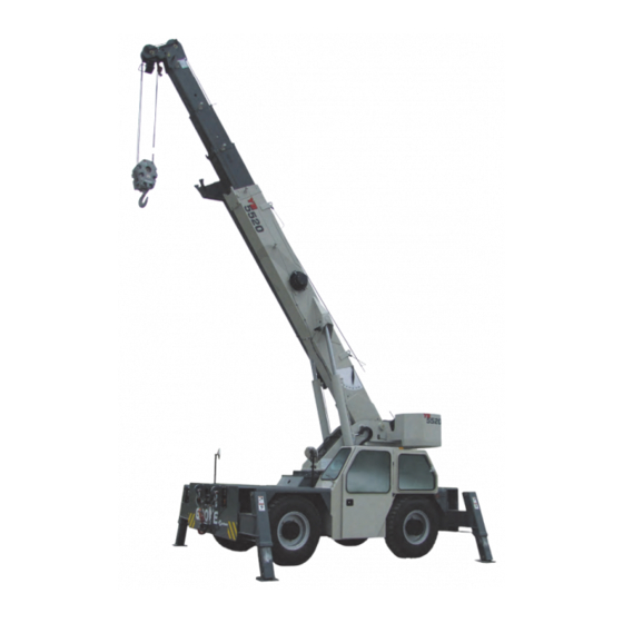
CD5520/YB5520 OPERATOR MANUAL INTRODUCTION NOMENCLATURE Item Description Item Description Counterweights Location 4th Boom Section Main Hoist Location 3rd Boom Section Engine Location 2nd Boom Section Outriggers (4) 1st Boom Section Rear Axle Main Control Valve Location Operator’s Cab Swing Motor and Gearbox Location Front Axle Lift Cylinders (2) Hook Block... - Page 12 INTRODUCTION CD5520/YB5520 OPERATOR MANUAL THIS PAGE BLANK Published 07-06-2017, Control # 406-03...
-
Page 13: Section 2
CD5520/YB5520 OPERATOR MANUAL SAFETY INFORMATION SECTION 2 SAFETY INFORMATION SECTION CONTENTS Safety Messages......2-1 Personnel Handling. -
Page 14: Safety Alert Symbol
Identifies hazards that may result in death or serious ACCIDENTS injury if the message is ignored. Following any accident or damage to equipment, the Manitowoc dealer must be immediately advised of the incident and consulted on necessary inspections and repairs. Should the dealer not be immediately available, CAUTION... -
Page 15: Operator Qualifications
CD5520/YB5520 OPERATOR MANUAL SAFETY INFORMATION operator at all times and must remain in the cab (if equipped) Ensure that all personnel working around the crane are or operator’s station while the crane is in use. thoroughly familiar with safe operating practices. You must be thoroughly familiar with the location and content of all The Operator Manual supplied with and considered part of placards and decals on the crane. -
Page 16: Operational Aids
(HCAS), a safe load indicator (SLI), or • When a Load Indicator, Rated Capacity Indicator, or an EKS5; Manitowoc refers to these systems as a rated Rated Capacity Limiter is inoperative or malfunctioning, capacity limiter (RCL) throughout its Operator and Service the designated person responsible for supervising the Manuals. -
Page 17: Working Area Limiter (If Equipped)
CD5520/YB5520 OPERATOR MANUAL SAFETY INFORMATION and overloaded in which case the hoist rope may fail preventing this condition. An Anti-Two-Block System is allowing the load, block, etc. to free fall. intended to assist the operator in preventing dangerous two- block conditions. It is not a replacement for operator Two-blocking is more likely to occur when both the main and awareness and competence. -
Page 18: Load Charts
SAFETY INFORMATION CD5520/YB5520 OPERATOR MANUAL mid-extend position (vertical stripe, if applicable), the outriggers must also be pinned when operating from the mid- extend position. Use adequate cribbing under outrigger floats to distribute weight over a greater area. Check frequently for settling. Read and follow the following safety decal for cranes with center front stabilizers. -
Page 19: Wind Forces
This information has been Wind forces can exert extreme dynamic loads. Manitowoc provided to assist in determining safe operation in windy recommends that a lift not be made if the wind can cause a conditions. - Page 20 SAFETY INFORMATION CD5520/YB5520 OPERATOR MANUAL NOTE: This condition is limited to operation with the main In both cases a) and b) above, the lift may also be limited by boom on fully extended outriggers only. the projected wind area of the load Ap and by the wind drag coefficient Cd: This limit can be determined by comparing c) If V(z) is >...
- Page 21 CD5520/YB5520 OPERATOR MANUAL SAFETY INFORMATION Simplified Method to Determine Maximum Permissible Wind Speed Determine 3-Second Gust 0.14 V(z) = [(z/10) + 0.4]v [m/s] Wind Speed at boom tip, 0.14 V(z) = [(z/33) + 0.4]v [mph] V(z) 13.4 m/s < V(z) < 20.1 m/s V(z) >...
- Page 22 Use tag lines when the wind gust speed is above 13.4 m/s (30 mph) to help control the movement of the Metric, with Z [m] and V [m/s] load. Manitowoc recommends that a lift not be made if 0.14 V(z) = [(Z/10) + 0.4] x V...
- Page 23 CD5520/YB5520 OPERATOR MANUAL SAFETY INFORMATION Calculation of Projected Wind Area (Ap) Wind Wind = 8 m = 24 m 25 ft 25 ft Wind Wind 10 ft 3 ft = 75 ft = 250 ft 10 ft 3 ft 8384-1 FIGURE 2-2 Determining Wind Drag Coefficient (Cd) If the exact Wind Drag Coefficient of a shape is not known,...
- Page 24 SAFETY INFORMATION CD5520/YB5520 OPERATOR MANUAL Table 2-2 Wind Drag Coefficient Maximum Permissible Wind Speed If the wind resistant area of the load Awr is greater than (load) Shape the allowable wind resistant area Awr , the ratio can be (allow) used to determine a permissible wind speed V(z) for the load 1.1 to 2.0 using Table 2-3.
- Page 25 CD5520/YB5520 OPERATOR MANUAL SAFETY INFORMATION Rated Load Chart Example - Metric 8383-1 FIGURE 2-3 Grove 2-13 Published 07-06-2017, Control # 406-03...
- Page 26 SAFETY INFORMATION CD5520/YB5520 OPERATOR MANUAL Table 2-4 Example-Capacity Reduction Factors for Wind Speed V(z) Greater than 13.4 m/s - Metric (Only for lifting with main boom on fully extended outriggers, with or without stowed extension) For wind speed V(z) (3-second gust speed at boom tip height) V(z) > 13.4 m/s ≤ 20.1 m/s, the Reduced Capacity shall be calculated by multiplying the Published Rated Capacity by the following factors: Main Boom Length in Meters Wind Speed...
- Page 27 CD5520/YB5520 OPERATOR MANUAL SAFETY INFORMATION At wind speeds greater than 13.4 m/s, it is not permissible to Load example 1.3a: lift a load greater than 12,040 kg, even if the wind resistance With large wind resistance area of the load Awr (load) area of the load is less than 14.45 m •...
- Page 28 SAFETY INFORMATION CD5520/YB5520 OPERATOR MANUAL • Is the load to be lifted less than allowable load? Ratio = 1.37 8,000 kg ≤ 12,040 kg • Is Awr less than Awr (load) (allow) From Table 2-5, the maximum permissible wind speed at ≤...
- Page 29 CD5520/YB5520 OPERATOR MANUAL SAFETY INFORMATION Rated Load Chart Example - Non-metric 8382-1 FIGURE 2-4 Grove 2-17 Published 07-06-2017, Control # 406-03...
- Page 30 SAFETY INFORMATION CD5520/YB5520 OPERATOR MANUAL Table 2-6Example-Capacity Reduction Factors for Wind Speed V(z) Greater than 30 mph - Non-metric (Only for lifting with main boom on fully extended outriggers, with or without stowed extension) For wind speed Vz (3-second gust speed at boom tip height) is greater > 30> mph ≤ 45 mph, the Reduced Capacity shall be calculated by multiplying the Published Rated Capacity by the following factors: Main Boom Length in Feet Wind Speed...
- Page 31 CD5520/YB5520 OPERATOR MANUAL SAFETY INFORMATION • Is Awr less than Awr (load) (allow) ≤ 119 ft 108 ft L i f t i n g L i m i t s a t w i n d s p e e d V ( z ) > 3 0 m p h Conclusion: This load is permissible to lift in wind speed up and ≤...
-
Page 32: Lifting Operations
SAFETY INFORMATION CD5520/YB5520 OPERATOR MANUAL Refer to the above Lifting Limits at wind speed V(z) injury could result from the crane tipping over or failing > 30 mph and ≤ 45 mph. Comparing the load and wind structurally from overload. resistant area to the allowable: The crane can tip over or fail structurally if: •... -
Page 33: Counterweight
The “balance point” for stability testing perform tilt-up panel lifting with two hoist lines poses new and according to SAE and Manitowoc criteria is a condition of different hazards than does normal lifting use. loading wherein the load moment acting to overturn the... -
Page 34: Pile Driving And Extracting
All hoist hooks shall be equipped with a positive locking driving or pile extraction is being considered. latch. It is not the intention of Manitowoc to recommend specific Crane Inspection types or makes of pile driving and pile extraction equipment, but rather to advise of the operational requirements to help •... -
Page 35: Electrocution Hazard
DANGER Electrocution Hazard! Thoroughly read, understand, and abide by all applicable Manitowoc cranes are not equipped with all features federal, state, and local regulations regarding operation of required to operate within OSHA 29CFR1926.1408, cranes near electric power lines or equipment. -
Page 36: Set-Up And Operation
SAFETY INFORMATION CD5520/YB5520 OPERATOR MANUAL Most overhead power lines are not insulated. Treat all Appoint a reliable and qualified signal person, equipped with overhead power lines as being energized unless you have a loud signal whistle or horn and voice communication reliable information to the contrary from the utility company equipment, to warn the operator when any part of the crane or owner. -
Page 37: Electrical Contact
2.0 m (6.6 ft)) at least 1.5 m (5 ft) into the any evidence of damage and all damaged parts are repaired ground. or replaced as authorized by your Manitowoc distributor or Moisten the soil around the metal rod (3) for better Manitowoc Crane Care. -
Page 38: Personnel Handling
ASME B30.5, Mobile and Locomotive Cranes, ASME B30.8, Floating Cranes and Floating Derricks, and in OSHA regulations 29CFR1910.180 for General Industry and 29CFR1926.1431 for Construction. Use of a Manitowoc crane to handle personnel is acceptable provided: • The requirements of the applicable national, state and local regulations and safety codes are met. -
Page 39: Environmental Protection
Manitowoc reminds crane owners to ensure that all safety requirements of applicable national, state and local decals are in place and legible. Manitowoc continues to urge regulations and safety codes are met. crane owners to upgrade their cranes with rated capacity •... -
Page 40: Lubrication
• Consult with Manitowoc Crane Care to determine if load pressure is relieved. To relieve hydraulic pressure, stop testing is required after a structural repair is performed. -
Page 41: Tires
Use only the hoist rope specified by Manitowoc as indicated rope. The nominal strength of a rope should never be on the crane’s Capacity Chart. Substitution of an alternate used as its working load. -
Page 42: Sheaves
SAFETY INFORMATION CD5520/YB5520 OPERATOR MANUAL • If an operator hoists the hook block up or down too fast Broken wires; number and location. when reeved with multiple parts of line and no hook load, Reduction in diameter. the wire rope can bird cage and damage the rope. Rope stretch (elongation). -
Page 43: Batteries
CD5520/YB5520 OPERATOR MANUAL SAFETY INFORMATION Inspect the boom nose and hook block sheaves for proper • Do not short across the battery posts to check charge. operation, excessive wear, and damage every 50 hours or Short circuit, spark, or flame could cause battery explosion. -
Page 44: Transporting The Crane
SAFETY INFORMATION CD5520/YB5520 OPERATOR MANUAL required, keep hands clear of the engine fan and other on the boom, it must be secured at the tie down on the carrier moving parts while performing maintenance. to prevent swinging. Be careful of hot surfaces and hot fluids when performing When using hookblock tie downs, excessive loading can be maintenance on or around the engine. -
Page 45: Work Practices
Always drive the crane carefully obeying speed limits and system that have not been evaluated and approved by highway regulations. Manitowoc Crane Care. Stay alert at the wheel. Do not step on surfaces on the crane that are not approved or suitable for walking and working. -
Page 46: Working
SAFETY INFORMATION CD5520/YB5520 OPERATOR MANUAL • Check for proper functioning of all controls and operator Never operate the crane when darkness, fog, or other aids (for example, RCL). visibility restrictions make operation unsafe. Never operate a crane in thunderstorms or high winds. •... -
Page 47: Lifting
CD5520/YB5520 OPERATOR MANUAL SAFETY INFORMATION Be sure the load is well secured and attached to the hook with rigging of proper size and in good condition. Check the hoist brake by raising the load a few inches, stopping the hoist and holding the load. Be sure the hoist brake is working correctly before continuing the lift. -
Page 48: Hand Signals
SAFETY INFORMATION CD5520/YB5520 OPERATOR MANUAL Be sure everyone is clear of the crane and work area before • Moving the crane in an area or direction in which the making any lifts. operator cannot clearly see the path of travel. Never swing over personnel, regardless of whether load is At all times use standardized hand signals - previously suspended from or attached to the boom. - Page 49 CD5520/YB5520 OPERATOR MANUAL SAFETY INFORMATION 8496-1 FIGURE 2-10 Grove 2-37 Published 07-06-2017, Control # 406-03...
-
Page 50: Jib
Use the most stable and secure position. However, Manitowoc caution handling and operating these components in sub- recognizes that certain jobsite conditions may not permit the zero temperatures, avoiding shock loading. -
Page 51: Temperature Effects On Hook Blocks
CD5520/YB5520 OPERATOR MANUAL SAFETY INFORMATION If applicable to your crane, frequently check all air tanks for The change in the length of a cylinder is proportional to the water in freezing weather. extended length of the cylinder and to the change in temperature of the oil in the cylinder. -
Page 52: Overload Inspection
SAFETY INFORMATION CD5520/YB5520 OPERATOR MANUAL Table 2-8: Boom Drift Chart (Cylinder length change in inches) Coeff. = 0.00043 (in / °F) STROKE Temperature Change (°F) (FT.) 0.26 0.52 0.77 1.03 1.29 1.55 1.81 2.06 2.32 2.58 0.52 1.03 1.55 2.06 2.58 3.10 3.61... - Page 53 To avoid an accident caused by overload damage to your crane: • Perform the inspections outlined in this publication for overloads up to 50%. • Stop operating the crane and contact Manitowoc Crane Care immediately for overloads of 50% and higher. Grove 2-41 Published 07-06-2017, Control # 406-03...
-
Page 54: Boom Inspection
SAFETY INFORMATION CD5520/YB5520 OPERATOR MANUAL Boom Inspection 2, 3 9, 10 2-42 Published 07-06-2017, Control # 406-03... - Page 55 CD5520/YB5520 OPERATOR MANUAL SAFETY INFORMATION Overload less than 25% Sheaves, Inspect all for damage. Rope Guides Collar-Wear Pads, Pad Inspect for damage. Retainers Overload from 25% to 49% Sheaves, Inspect all for damage. Rope Guides Collar-Wear Pads, Pad Inspect all for damage. Retainers Collar-welds Inspect all for damage.
-
Page 56: Superstructure Inspection
SAFETY INFORMATION CD5520/YB5520 OPERATOR MANUAL Superstructure Inspection 10,11 8, 9 2-44 Published 07-06-2017, Control # 406-03... - Page 57 CD5520/YB5520 OPERATOR MANUAL SAFETY INFORMATION Overload less than 25% Lift Cylinder Inspect for leaking. See topic in Introduction section Wire Rope Inspect all for damage. of Service Manual. Turntable See topic in Swing section of Check bolts for proper torque. Bearing Service Manual.
-
Page 58: Carrier Inspection
SAFETY INFORMATION CD5520/YB5520 OPERATOR MANUAL Carrier Inspection 5, 6 2-46 Published 07-06-2017, Control # 406-03... - Page 59 CD5520/YB5520 OPERATOR MANUAL SAFETY INFORMATION Overload less than 25% Jack Cylinders Inspect for leaking. Outrigger Inspect for deformation and cracked welds. Pads Overload from 25% to 49% Jack Cylinders Inspect for leaking. Outrigger Inspect for deformation and cracked welds. Pads Outrigger Inspect for deformation and cracked welds.
- Page 60 SAFETY INFORMATION CD5520/YB5520 OPERATOR MANUAL THIS PAGE BLANK 2-48 Published 07-06-2017, Control # 406-03...
-
Page 61: Controls, Switches, And Gauges
CD5520/YB5520 OPERATOR MANUAL OPERATING CONTROLS AND PROCEDURES SECTION 3 OPERATING CONTROLS AND PROCEDURES SECTION CONTENTS Controls, Switches, and Gauges....3-1 Hoist........3-16 Cab Controls . - Page 62 OPERATING CONTROLS AND PROCEDURES CD5520/YB5520 OPERATOR MANUAL Accelerator Pedal Brake Pedal Accelerator Pedal (5) controls the travel speed and hydraulic Pressing down on the Brake Pedal (6) applies the service work function speeds of the crane. Pressing down on the brakes located in the front and rear axles and slows and accelerator pedal increases the engine speed.
-
Page 63: Left Dash Controls
CD5520/YB5520 OPERATOR MANUAL OPERATING CONTROLS AND PROCEDURES Press the button on the end of the lever to sound the horn. Error Code Screen Toggle Switch The Error Code Screen Toggle Switch (4) is a push-button Left Dash Controls switch used to scroll through the error codes shown on the Refer to Figure 3-2. -
Page 64: Right Dash Controls
OPERATING CONTROLS AND PROCEDURES CD5520/YB5520 OPERATOR MANUAL Right Dash Controls The RCL will be overridden only as long as the switch is depressed. Refer to Figure 3-3. Pressing the top of the switch re-engages the boom down, telescope out and winch up controls after these functions were disabled when an overload condition was sensed by the RCL. - Page 65 CD5520/YB5520 OPERATOR MANUAL OPERATING CONTROLS AND PROCEDURES To WIND rope onto the winch, press the bottom of the switch. engage the lock, press the top of the switch to disengage the lock. 360° Swing Lock Switch This switch (10) engages the 360° swing lock to lock the turntable in any position.
-
Page 66: Indicator And Gauge Display
OPERATING CONTROLS AND PROCEDURES CD5520/YB5520 OPERATOR MANUAL Indicator and Gauge Display As a system check, the indicators will come on for two seconds when the ignition switch is turned to the RUN position. FIGURE 3-4 (Figure 3-4) Item Numbers Item Description Item Description... - Page 67 CD5520/YB5520 OPERATOR MANUAL OPERATING CONTROLS AND PROCEDURES Fuel Gauge Minimum Wrap Indicator The Fuel Gauge (1) (Figure 3-4) indicates the quantity of fuel The Minimum Wrap Indicator (11) illuminates red when the in the fuel tank and has a scale calibrated from 0 (empty) to wire rope is down to the last three wraps on the hoist drum;...
-
Page 68: Crane Level Indicator
OPERATING CONTROLS AND PROCEDURES CD5520/YB5520 OPERATOR MANUAL Low Brake Pressure Indicator Crane Level Indicator This is a bubble-type indicator (Figure 3-5) that allows the operator to level the crane when using the outrigger controls. See Bubble Level Adjustment, page 3-19. WARNING When the low brake pressure warning light is illuminated, immediately stop and shutdown the crane. -
Page 69: Air Conditioning/Heater Controls
CD5520/YB5520 OPERATOR MANUAL OPERATING CONTROLS AND PROCEDURES Boom Angle Indicator The boom angle indicator (Figure 3-8) is a plumb arrow and a decal with angular graduations from 0° to 80°. One is located on both sides of the boom and is visible from the operator’s cab in most boom positions. -
Page 70: Steering Controls
OPERATING CONTROLS AND PROCEDURES CD5520/YB5520 OPERATOR MANUAL Two-Wheel Steer Mode The front wheels steer the crane (Figure 3-11). The rear wheels remain in the fixed straight ahead position. This mode is used for highway travel and traveling at higher speeds. a0610 FIGURE 3-11 Four-Wheel Steer Mode... -
Page 71: Operator's Cab
CD5520/YB5520 OPERATOR MANUAL OPERATING CONTROLS AND PROCEDURES All wheels steer in the same direction (Figure 3-13). This p0510 mode permits the operator to move the crane sideways for short distances. This feature is especially helpful in repositioning the crane in tight areas. FIGURE 3-15 a0566 FIGURE 3-13... -
Page 72: Seat Adjustment
OPERATING CONTROLS AND PROCEDURES CD5520/YB5520 OPERATOR MANUAL Seat Adjustment Opening the Door from Inside Pull the door handle back to release the cab door latch Adjust the operator’s seat correctly. Full foot pedal control (Figure 3-18). must be obtained with your back firmly against the seat back. Seat Fore &... -
Page 73: Crane Operation
CD5520/YB5520 OPERATOR MANUAL OPERATING CONTROLS AND PROCEDURES CRANE OPERATION Starting the Engine Normal Engine Starting NOTE: Never leave the engine running while the crane is unattended. Shut off the engine to prevent unauthorized persons from operating the controls. Walk around the crane and warn all personnel who may be servicing the crane or are in the crane’s path prior to starting. - Page 74 OPERATING CONTROLS AND PROCEDURES CD5520/YB5520 OPERATOR MANUAL Do not press the accelerator pedal, the engine ECM will Stop all electrical loads (lights, heaters, etc.) determine the proper idle speed. If the engine fails to start on the first try, wait until the starter motor comes to a complete stop;...
-
Page 75: Cold Climate Engine Operation
Warm-up Procedures for All Temperature Ranges: Lubrication section of your crane’s Operator Manual, by Upon startup, allow the engine to idle for 3 to 5 minutes contacting your local Manitowoc distributor, or by contacting before operating with a load. Manitowoc Crane Care directly). -
Page 76: Hoist
If there is any unusual sound coming from the Swing Drive and Turntable Bearing crane’s hydraulic pumps or motors, stop the operation and engine immediately and contact a Manitowoc Warm-up Procedures for Temperatures Above -7°C distributor. (20°F): •... -
Page 77: Traveling With The Crane
CD5520/YB5520 OPERATOR MANUAL OPERATING CONTROLS AND PROCEDURES Traveling with the Crane Start the engine and disengage the parking brake. w0027 CAUTION To avoid damage to the parking brake and crane, do not apply the parking brake while traveling. Disengage the parking brake before driving. Damage to the crane can occur. -
Page 78: Changing Travel Direction
OPERATING CONTROLS AND PROCEDURES CD5520/YB5520 OPERATOR MANUAL NOTE: Check the instrument panel gauges frequently It is recommended that the crane come to a complete during operation. Any abnormal readings should be stop before shifting between forward and reverse. investigated and corrected as soon as possible. The following practices could result in transmission failure: Changing Travel Direction •... - Page 79 CD5520/YB5520 OPERATOR MANUAL OPERATING CONTROLS AND PROCEDURES A working crane may settle during lifting operations. same time. Individual operation is accomplished by selecting Frequently check the crane for level. When rechecking the the desired Outrigger/Select Switch. crane for level, the boom must be positioned over the front of Extending the outriggers the crane, fully lowered to horizontal and fully retracted (for cranes fitted with a boom rest, the boom shall be stowed...
-
Page 80: Outrigger Monitoring System (Oms) (Optional-Standard In North America)
OPERATING CONTROLS AND PROCEDURES CD5520/YB5520 OPERATOR MANUAL output contact will then close illuminating the green indicator on the control panel signaling all outriggers are fully extended and lifts can be made per “outriggers fully extended” Load Chart. Any outrigger beam not fully extended or functional failure of any proximity switch will cause the indicator to not illuminate, indicating outrigger beams are not fully extended and lifts can only be made per the “outriggers retracted”... -
Page 81: Operating The Boom Controls
CD5520/YB5520 OPERATOR MANUAL OPERATING CONTROLS AND PROCEDURES Boom Swing Operation Before rotating the mast, be sure there is enough clearance on all sides and that all persons are away from the area. A pinch point between the operator’s cab and mast can cause injury or death. - Page 82 OPERATING CONTROLS AND PROCEDURES CD5520/YB5520 OPERATOR MANUAL a0578 a0576 FIGURE 3-32 Boom Telescope Operation To Stop Extension/Retraction Slowly move the control lever to the neutral position and decrease the engine speed to idle. WARNING To Retract the Boom Always operate the hoist control to unwind the wire rope when extending the boom.
- Page 83 CD5520/YB5520 OPERATOR MANUAL OPERATING CONTROLS AND PROCEDURES WARNING When lifting at high boom angles with an extended boom, it is crucial to maintain proper side slide pad adjustment. Visually check the lateral straightness of the boom before raising the load. Lifting with a boom which is not visually straight may cause boom failure and could result in injury or death.
- Page 84 OPERATING CONTROLS AND PROCEDURES CD5520/YB5520 OPERATOR MANUAL To Lower the Boom lever (Figure 3-35) until the desired lowering speed is obtained. The further the control is pushed forward the faster Press the accelerator pedal to increase the engine speed to the boom will lower.
- Page 85 CD5520/YB5520 OPERATOR MANUAL OPERATING CONTROLS AND PROCEDURES Hoist Operation CAUTION Never put side loads on the boom. Side loads can damage the swing gearbox. Move the boom so that it is directly above the load before lifting the load. Do not let the hookblock touch the boom head. An automatic cutout device is installed on this crane to prevent the hookblock from being pulled into the boom head.
- Page 86 OPERATING CONTROLS AND PROCEDURES CD5520/YB5520 OPERATOR MANUAL Hoist Rotation Indicator attached to the hoist. A pulsating signal is sensed by the operator’s thumb during hoist operation. The hoist rotation indicator is located on the top of the hoist controller. The indicator is electronically driven by a sensor a0584 a0583 FIGURE 3-36...
-
Page 87: Optional Controls Operation
CD5520/YB5520 OPERATOR MANUAL OPERATING CONTROLS AND PROCEDURES Optional Controls Operation away from the area. Injury can be caused if the wire rope breaks or the hook becomes disconnected. Under Deck Winch To Extend the Wire Rope w0031 Push and hold the top of the switch (Figure 3-37). Keep tension on the wire rope to prevent twisting of the wire rope on the winch drum. -
Page 88: Operating Practices
OPERATING CONTROLS AND PROCEDURES CD5520/YB5520 OPERATOR MANUAL OPERATING PRACTICES That the boom when extended, is laterally straight. b. That the hoist rope is not kinked or damaged. Handling a Load That multiple-part lines are not twisted around each The crane must not be loaded beyond the specifications of other. -
Page 89: Traveling With A Load (Pick And Carry)
To avoid damage to the parking brake and crane, do not models are in compliance with Manitowoc Crane Care’s apply the parking brake while traveling. recommendations. The operator of the crane assumes Disengage the parking brake before driving. -
Page 90: Turning Clearances
OPERATING CONTROLS AND PROCEDURES CD5520/YB5520 OPERATOR MANUAL and in the work area, before moving the platform up or down. w0018 • Always lower the platform to the travel position (boom fully retracted and lowered) before moving the crane. NOTE: Make sure that required restraining items, such as railings, chains, cables, body belts with lanyards, etc. -
Page 91: Using The Capacity Chart
CD5520/YB5520 OPERATOR MANUAL CAPACITY CHART SECTION 4 CAPACITY CHART SECTION CONTENTS Using the Capacity Chart ....4-1 Chart ........4-1 Operating Boom Radius . -
Page 92: Lifting With The Boom Extension Installed
CAPACITY CHART CD5520/YB5520 OPERATOR MANUAL speed of 4 km/h (2.5 mph) on a smooth level surface with the boom retracted to the shortest length possible a0063 and centered over the front. Do not use the boom extension on rubber. For operating radius not shown on the Capacity Chart, use load rating of the next larger radius. - Page 93 CD5520/YB5520 OPERATOR MANUAL CAPACITY CHART a0870 FOR REFERENCE ONLY USE THE CAPACITY CHART IN THE OPERATOR’S CAB FIGURE 4-3 Grove Published 07-06-2017, Control # 406-03...
- Page 94 CAPACITY CHART CD5520/YB5520 OPERATOR MANUAL THIS PAGE BLANK Published 07-06-2017, Control # 406-03...
-
Page 95: Section 5
CD5520/YB5520 OPERATOR MANUAL ATTACHMENTS SECTION 5 ATTACHMENTS SECTION CONTENTS Pivoting Boom Head......5-1 Stowing the Boom Extension....5-11 Boom Head Positions . - Page 96 ATTACHMENTS CD5520/YB5520 OPERATOR MANUAL 0° FIGURE 5-2 a0594 Published 07-06-2017, Control # 406-03...
-
Page 97: Changing The Boom Head Position (No Boom Extension)
CD5520/YB5520 OPERATOR MANUAL ATTACHMENTS Changing the Boom Head Position (No Boom Extension) Position 1 Wire Rope Position 2 Lower and retract the boom. Lower the block or ball to the ground to take weight off of the wire rope and boom head. Remove the retaining clip from the rope retention pin, remove the rope retention pin from the top of the boom head (Figure 5-6). -
Page 98: Adjusting The Boom Extension Offset
ATTACHMENTS CD5520/YB5520 OPERATOR MANUAL Rope Retention Pivot Lock Pin p0369 FIGURE 5-6 Adjusting the Boom Extension Offset FIGURE 5-7 p0395 With the boom extension supported, remove the pivot lock pin (Figure 5-8). It will be necessary to remove the DANGER boom extension weight on the pin in order to remove it. -
Page 99: Hoist Block
CD5520/YB5520 OPERATOR MANUAL ATTACHMENTS NOTE: It may be necessary to remove and stow the retention pin for later application. Raise the hook and ball. Check that the wire rope is engaged in all the sheaves in the boom, hoist block and hoist drum. - Page 100 ATTACHMENTS CD5520/YB5520 OPERATOR MANUAL possibility the boom extension could swing away from the main boom as soon as it is released. Completely retract and lower the boom. Position the boom head angle at 0°. Remove the four boom extension attaching pins from the boom extension, as shown in Figure 5-11.
- Page 101 CD5520/YB5520 OPERATOR MANUAL ATTACHMENTS FIGURE 5-15 p0374 p0373 FIGURE 5-14 Remove the pin from the swing bracket, as shown in Figure 5-15. Grove Published 07-06-2017, Control # 406-03...
- Page 102 ATTACHMENTS CD5520/YB5520 OPERATOR MANUAL Swing the boom extension fully to the front and install 11. Install the anchor bracket pin (Figure 5-18). the remaining two link pins. (Figure 5-16). FIGURE 5-18 p0377 12. Remove the pin from the deflector sheave bracket. Flip up the deflector sheave bracket to the upright position p0375 FIGURE 5-16...
- Page 103 CD5520/YB5520 OPERATOR MANUAL ATTACHMENTS 13. Connect the boom extension’s anti-double block wire with the anti-double block wire on the main boom (Figure 5-20). FIGURE 5-20 p0379 14. Remove hook ball from storage FIGURE 5-21 p0380 compartment on the crane and place it below the end of the boom extension.
-
Page 104: Manually Extendable Jib (Optional)
ATTACHMENTS CD5520/YB5520 OPERATOR MANUAL 18. Remove the two retaining pins from the boom extension head (Figure 5-23). FIGURE 5-25 p0384 FIGURE 5-23 p0382 21. Install the hook and block to the wire rope. See Attaching Hook and Ball. 19. Install the wire rope over the deflector sheave (Figure 5-24) and install the pin. -
Page 105: Stowing The Boom Extension
CD5520/YB5520 OPERATOR MANUAL ATTACHMENTS Stowing the Boom Extension To stow the boom extension, perform the following procedure: Make sure the offset angle is set at 0° before attempting to stow the boom extension. Make sure the crane is level before attempting to stow the boom extension. - Page 106 ATTACHMENTS CD5520/YB5520 OPERATOR MANUAL FIGURE 5-30 Extension Anchor Bracket Pin p0377 Swing the boom extension backward until it makes contact with swing bracket. Align the swing bracket with the bracket on the boom extension. Then push the boom extension mounting bracket onto the swing bracket. Install the pin (Figure 5-31).
-
Page 107: Searcher Hook Assembly
CD5520/YB5520 OPERATOR MANUAL ATTACHMENTS SEARCHER HOOK ASSEMBLY Installation The searcher hook is a fixed hook that mounts to the boom Using a suitable lifting device raise the searcher hook (1, nose. The searcher hook has a maximum capacity of 6000 lb Figure 5-34) in front of the boom nose and align the (2722 kg). -
Page 108: Down Haul Weight
ATTACHMENTS CD5520/YB5520 OPERATOR MANUAL DOWN HAUL WEIGHT a1665 Installing the Down Haul Weight Whenever a single part line is used on a crane to lift a load, the load indicator transmitter must be removed from the boom head and installed onto the down haul weight. Without the transmitter installed and attached to the load pin, the load indicator receiver in the cab will not register the weight being lifted by the single part line. -
Page 109: Installing Cable On The Hoist
CD5520/YB5520 OPERATOR MANUAL ATTACHMENTS Install the hoist block using instructions in Installing the Hook Block, page 5-5. Install the load pin. Connect the transmitter wire (Figure 5-35) and the load pin wire to the jumper wire. INSTALLING CABLE ON THE HOIST CAUTION If cable is wound from the storage drum, the reel should be rotated in the same direction as the hoist. -
Page 110: Wire Rope Wedge Socket
Of the methods shown below, Manitowoc prefers that Wedge Socket method A or F be used, that is, clipping a short piece of wire... - Page 111 CD5520/YB5520 OPERATOR MANUAL ATTACHMENTS Specialty Clip Specialty Wedge Wedge Socket FIGURE 5-39 Table 5-1 Wire Rope Clip Torque Values Clip Sizes Torque Inches lb-ft 3.18 3/16 4.76 6.35 5/16 7.94 13.28 7/16 11.11 12.70 9/16 14.29 15.88 19.05 22.23 25.40 1-1/8 28.58 1-1/4...
-
Page 112: Reeving
ATTACHMENTS CD5520/YB5520 OPERATOR MANUAL REEVING threading the rope through the second sheave in the hoist block. See Figure 5-40. Reeving for 4-part Line NOTE: It may be easier to place the wire rope over the sheaves if you remove the hair pins and wire rope Place the wire rope over the top sheave in the boom head retaining pins from the boom head and hoist block. -
Page 113: Section 6
CD5520/YB5520 OPERATOR MANUAL MAINTENANCE SECTION 6 MAINTENANCE SECTION CONTENTS Introduction....... 6-1 Checking Tire Pressure . -
Page 114: Safety List
ENGINE - Check operation. Remove all dirt or debris, and all flammable materials before running engine. LUBRICANTS It is not the policy of Manitowoc to publish lists of approved lubricants or guarantee lubricant performance. The responsibility for the quality rests completely with the distributor or manufacturer of the lubricant. -
Page 115: After First 50 Hours Of Operation (New Cranes)
CD5520/YB5520 OPERATOR MANUAL MAINTENANCE Anti-Double-Blocking System Cranes Not In Regular Use • Check that the system is working properly. A crane which has been idle for a period of one month or more, but less than six months, must be given an inspection Controls by a qualified person. - Page 116 MAINTENANCE CD5520/YB5520 OPERATOR MANUAL 1000 Daily 2000 Hours Hours Hours Service Check before Hours Hours Hours Three operation Weekly Monthly Yearly Weeks Months Months Inspect the anti-double blocking system Inspect the wire rope Inspect reeving, clamps and connections Inspect the lifting hook Inspect safety devices Check controls operation Check engine crankcase oil level...
- Page 117 CD5520/YB5520 OPERATOR MANUAL MAINTENANCE 1000 Daily 2000 Hours Hours Hours Service Check before Hours Hours Hours Three operation Weekly Monthly Yearly Weeks Months Months Check axle wheel hub lubricant level (4) Check axle housing lubricant level (2) Check hoist gearbox and brake lubricant level Lubricate the outrigger slides Add grease to swing gearbox...
-
Page 118: Lubrication Points
MAINTENANCE CD5520/YB5520 OPERATOR MANUAL Lubrication Points NOTE: Drive shaft u-joints do not require routine lubrication. Lubricate only after major axle Apply grease to the following fittings after the first 20 hours of overhaul. operation, thereafter every 50 hours of operation. Use a Lithium Base, E.P. - Page 119 CD5520/YB5520 OPERATOR MANUAL MAINTENANCE Lube Both Sides. Boom Head Sheaves and Pivot Lube Points FIGURE 6-3 p0389 Steering Knuckle Lube Points (Front Axle) FIGURE 6-5 p0417 Lube Both Sides on Both Ends. Lift Cylinder Pivots Lube Points FIGURE 6-4 Steering Knuckle Lube Points p0390 (Rear Axle) FIGURE 6-6...
- Page 120 MAINTENANCE CD5520/YB5520 OPERATOR MANUAL Pivot Lube Points FIGURE 6-11 (Rear Axle) p0423 Steering Link Lube Points FIGURE 6-8 (Rear Axle) p0422 Steering Cylinder Pivot Ends Lube p0418 Points (Front Axle) FIGURE 6-9 Drop Block Lube Point FIGURE 6-12 p0391 Steering Cylinder Pivot Lube Points Boom Extension Head Sheave (Rear Axle) FIGURE 6-10...
-
Page 121: Scheduled Maintenance
CD5520/YB5520 OPERATOR MANUAL MAINTENANCE Inspect the terminal ends of the wire rope for damaged parts, loose clamps or wrong installation. DANGER Loads may fall if the wedge and socket is not installed properly or has damage. A falling load can injure or kill. Do not operate the crane if any of the above are found. - Page 122 MAINTENANCE CD5520/YB5520 OPERATOR MANUAL install the dipstick and close the engine compartment cover. WARNING Checking the Transmission Oil Level NOTE: When checking the transmission oil level, also c h e c k t h e i n d i c a t o r ( F i g u r e 6 -1 7 ) o n t h e transmission filter.
- Page 123 CD5520/YB5520 OPERATOR MANUAL MAINTENANCE Checking Engine Coolant Level Drain Water From Engine Fuel Filter Shut off the engine and engage the parking brake. Refer to the engine manual furnished with the crane and follow the water draining instructions. Checking Hydraulic Oil Level If the hydraulic oil is constantly low, check for leaks in the hydraulic system.
-
Page 124: Checking Tire Pressure
MAINTENANCE CD5520/YB5520 OPERATOR MANUAL Checking the Air Cleaner Restriction Indicator Installing the Element The air cleaner is equipped with a filter restriction indicator Install the secondary element in the housing and slide it (1) (Figure 6-22). The air cleaner element needs to be all the way in. -
Page 125: Grease Fittings
Inner Boom Pad Lubrication • 6.35 mm (0.25 inch) diameter nozzle grease gun tip (Grove P/N 955045). Contact Manitowoc Crane Care to With the boom fully retracted, apply grease to the wear obtain this tip. pads on the top of second boom section with a small paint brush or a grease gun. -
Page 126: Side And Bottom Boom Wear Pad Lubrication
Apply grease to the fitting on the parking brake. See section Protecting Cranes From Rusting on Lubrication for grease type. Manitowoc Crane Group's cranes are manufactured to high Heater/Air Conditioner Filter quality standards, including the type of paint finish demanded by today's industry. In partnership with our paint Remove thumb screws to access filter. -
Page 127: Cleaning Procedures
To help protect against corrosion of Grove cranes, prior to shipment. When applied the product has a red tint to Manitowoc Crane Care recommends washing the crane at allow applicators to view coverage during application. This least monthly to remove all foreign matter. More frequent... -
Page 128: Application
Apply a finish coat of paint using accepted blending necessary. techniques. Use of original paint colors is recommended Please contact Manitowoc Crane Care should you have any to insure the best color match possible. questions. For scratches and marks in areas of low visibility: Areas of Application •... - Page 129 CD5520/YB5520 OPERATOR MANUAL MAINTENANCE 15, 16 FIGURE 6-25 Grove 6-17 Published 07-06-2017, Control # 406-03...
- Page 130 MAINTENANCE CD5520/YB5520 OPERATOR MANUAL FIGURE 6-25 continued 6-18 Published 07-06-2017, Control # 406-03...
- Page 131 CD5520/YB5520 OPERATOR MANUAL MAINTENANCE Item Description Headache Ball/Hook Block Item Description Turntable Bearing Fasteners Hoist Tension Spring O/R Pins, Clips Hoist Hose Connections Hook block Tiedown Cable Pivot Shaft O/R Hose Connections Wire Rope Entire underside of unit Hose Connections inside turntable Powertrain Hardware inside compartment All Hardware, Clips, Pins, Hose Connections not painted O/R Pins, Clips...
- Page 132 MAINTENANCE CD5520/YB5520 OPERATOR MANUAL THIS PAGE BLANK 6-20 Published 07-06-2017, Control # 406-03...
- Page 133 CD5520/YB5520 OPERATOR MANUAL ADJUSTMENTS SECTION CONTENTS ADJUSTMENTS All adjustments must be performed by a qualified mechanic. Refer to the Service Manual for the proper procedures. Grove Published 07-06-2017, Control # 406-03...
- Page 134 ADJUSTMENTS CD5520/YB5520 OPERATOR MANUAL THIS PAGE BLANK Published 07-06-2017, Control # 406-03...
-
Page 135: Section 7
CD5520/YB5520 OPERATOR MANUAL SPECIFICATIONS SECTION 8 SPECIFICATIONS SECTION CONTENTS Lubricants and Capacities ....8-1 TIRES ........8-5 Engine Oil Specifications . -
Page 136: Engine Oil Specifications
SPECIFICATIONS CD5520/YB5520 OPERATOR MANUAL Engine Oil Specifications temperatures. A multigrade oil is therefore recommended with the viscosity grades shown in the following chart. The Cummins Oil Registration List use of single grade lubricating oils is not recommended, except for synthetic oils used in Arctic conditions. Cummins has a program that lists engine oils that it has tested to meet its engineering specifications. -
Page 137: Diesel Fuel
CD5520/YB5520 OPERATOR MANUAL SPECIFICATIONS API, SAE ASTM Classification DIESEL FUEL SG/CD, SF/CC The Cummins Diesel Engine operates most efficiently with ultra low sulfur No. 2 diesel fuel in temperatures above 0°C Do not use SD or SC API classification oils. These oils do not (32°F). -
Page 138: General Specifications
SPECIFICATIONS CD5520/YB5520 OPERATOR MANUAL GENERAL SPECIFICATIONS ENGINE Diesel Engine Make and Model..................Cummins QSB3.3 diesel Type of Aspiration ..................Turbocharged Horse Power ....................99 hp @ 2600 rpm Low Idle Speed................... 800 rpm Maximum Engine Speed ................2600 rpm BOOM Construction.................... -
Page 139: Tires
CD5520/YB5520 OPERATOR MANUAL SPECIFICATIONS Length ....................97.5 m (320 ft) Diameter....................14 mm Type .......................8 x 25 EIPS-IWRC Length ....................97.5 (320 ft) Wire Rope (Optional Below Deck Winch): Diameter....................11.1 mm (7/16 in) Length ....................35.1 m (115 ft) TRANSMISSION Model ......................International - Powershift Type .......................4 speed forward and 4 speed reverse TORQUE CONVERTER Model ......................Borg and Beck S-11... -
Page 140: Operating Dimensions
SPECIFICATIONS CD5520/YB5520 OPERATOR MANUAL • 3rd gear...................... 21 km/hr (13 mph) • 4th gear ...................... 34 km/hr (21 mph) OPERATING DIMENSIONS TWO-WHEEL STEER • Outside turning radius (center line outside tires) ................6.06 m (19' 11“) • Minimum aisle space for 90° turn (center line inside tires) ................ - Page 141 ALPHABETICAL INDEX 100 Hours Of Operation and Over......... 6-14 50 Hours Of Operation.
- Page 142 OPERATOR MANUAL CD5520/YB5520 Work Practices ............2-33 APL-2 Published 07-06-2017, Control # 406-03...
Need help?
Do you have a question about the Shuttlelift CD5520 and is the answer not in the manual?
Questions and answers