Table of Contents
Advertisement
Quick Links
Advertisement
Table of Contents
Troubleshooting

Subscribe to Our Youtube Channel
Related Manuals for Manitowoc CD25


Summary of Contents for Manitowoc CD25
- Page 1 CD25 Service Manual...
- Page 2 This Page Blank...
- Page 3 DANGER An untrained operator subjects himself and others to death or serious injury. Do not operate this crane unless: Manitowoc is not • You are trained in the safe operation of this crane. responsible for qualifying personnel. •...
- Page 4 CALIFORNIA PROPOSITION 65 WARNING Diesel engine exhaust and some of its constituents are known to the State of California to cause cancer, birth defects, and other reproductive harm. CALIFORNIA PROPOSITION 65 WARNING Battery posts, terminals, and related accessories contain chemical lead and lead compounds, chemicals known to the State of California to cause cancer, birth defects or other reproductive harm.
-
Page 5: Table Of Contents
CD25 TABLE OF CONTENTS TABLE OF CONTENTS SECTION 1 ........Introduction Directional Reference . - Page 6 TABLE OF CONTENTS CD25 Battery Maintenance and Charging ........3-6 Battery Replacement .
- Page 7 CD25 TABLE OF CONTENTS Telescope Circuit ............4-26 General .
- Page 8 TABLE OF CONTENTS CD25 Booms and Main Frame ..........5-14 Drive Train .
- Page 9 CD25 TABLE OF CONTENTS Description ............5-42 Cleaning Procedures .
- Page 10 TABLE OF CONTENTS CD25 Axle Hub and Axle Half Shaft Disassembly ......8-13 Axle Hub and Axle Half Shaft Assembly .
- Page 11 CD25 TABLE OF CONTENTS Bleeding Steering System......... . . 10-23 SECTION 11 .
- Page 12 TABLE OF CONTENTS CD25 This Page Blank TOC-8...
-
Page 13: Directional Reference
Weld Studs ......1-12 This manual contains information on maintenance, service and repair of the Model CD25 cranes. Major components Serial Number Decal and systems are included, except service on the engine. -
Page 14: Specifications
INTRODUCTION CD25 SPECIFICATIONS ENGINE Diesel Engine Make and Model..................Cummins QSB4.5L diesel Type of Aspiration ..................Turbocharged Horsepower....................130 hp @ 2500 rpm Low Engine Idle Speed................800 rpm Intermediate Speed Control (ISC) Idle Speed ..........1200 rpm - Coolant Temperature is less than 71°... - Page 15 CD25 INTRODUCTION TORQUE CONVERTER/TRANSMISSION Manufacturer ....................Dana Transmission Type ......................Hydraulic Powershift FRONT AXLE DRIVE Type ......................International Transmissions Limited Model ......................SD80 - Center Drive Head REAR AXLE DRIVE Type ......................International Transmissions Limited Model ......................SD80 - Center Drive Head OUTRIGGERS Type ......................Hydraulic Construction ....................1-stage hydraulic telescoping beam...
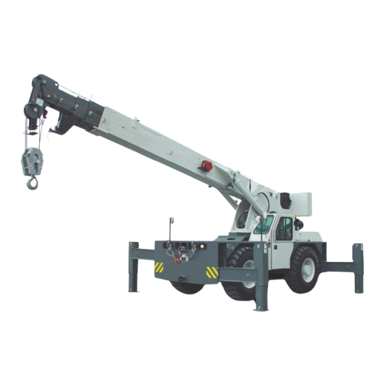
- Page 16 INTRODUCTION CD25 Item Description Item Description Winch Outriggers Hydraulic Valve Location (Below Deck) Fuel Tank Mast w/ Swing Gear Folding Boom Extension Hoist Hook Block Drive/Steer Axles Storage Compartments Lift Cylinder (2) Hydraulic Tank Air Cleaner Published 5-24-2017, Control# 587-01...
-
Page 17: General Service Information
CD25 INTRODUCTION GENERAL SERVICE INFORMATION surfaces. Keep the parts in the solution long enough to be thoroughly cleaned and heated. Flush the parts thoroughly Appropriate service methods and proper repair procedures after cleaning to remove all residue of the alkali solution. -
Page 18: Hoses And Tubes
INTRODUCTION CD25 HOSES AND TUBES Installation When installing a new hose, loosely connect each end and make sure the hose takes up the designed position DANGER before tightening the connection. Clamps should be High Pressure/Temperature Hazard! tightened sufficiently to hold the hose without crushing Exercise extreme care around pressurized hydraulic and to prevent chafing. -
Page 19: Hydraulic Fittings
Follow the F.F.F.T. method, described above. Flats from Finger Tight (F.F.F.T.) Method Table 1-1: Tube and Swivel Nut/Hose Fittings Manitowoc recommends that the F.F.F.T. tightening method described here be used when assembling all hydraulic fittings. This method will minimize the risk of fitting damage or failure due to under or overtightening. -
Page 20: Hydraulic Pressure Testing
Loctite types are suitable for all applications. Various types of Loctite are specified throughout the Service Manual. The following types of Loctite brand adhesives are available from the Parts Department of the local Manitowoc distributor. Non-Adjustable Fitting to Port FIGURE 1-6... -
Page 21: Fasteners And Torque Values
The use of handle and nuts being used. extensions will change applied torque to the bolt. The torque tables are provided by Manitowoc Crane Care for All handles must be parallel to the step wrench during reference when performing maintenance (see Figure 1-8). - Page 22 INTRODUCTION CD25 Multiplier bar handles must be propped or supported To convert pounds-foot (lb-ft) of torque to newton meters within the outer 1/4 of the handle length, or serious (Nm), multiply the pounds-foot quantity by 1.3558. under or over tightening will occur.
- Page 23 CD25 INTRODUCTION Table 1-6: Metric Fasteners, Coarse Thread, Zinc-Flake Coating Bolt Diameter - Metric Torque Values (Nm) Class 21.6 42.4 73.1 1195 1608 2072 10.9 12.5 31.5 62.0 1325 1800 2450 3150 12.9 15.0 36.0 75.0 1060 1550 2125 2850...
-
Page 24: Weld Studs
INTRODUCTION CD25 Table 1-11: Metric coarse Thread: Torque Values for Torque Value Stainless Steel Fasteners with Oil Lubrication Size lb-in lb-ft Torque #10 (0.190) — Value Size — 5/16 M2.5 17.5 7/16 — — — 13.0 NOTE: Stainless steel fasteners tend to gall while being 27.0... -
Page 25: Section 2
CD25 SAFETY PRACTICES SECTION 2 SAFETY PRACTICES SECTION CONTENTS Introduction....... 2-1 General Considerations . -
Page 26: Personal Considerations
SAFETY PRACTICES CD25 Personal Considerations What to do Clothing Check to see that you are suitably The wrong cloths or carelessness in clothed. For certain work it may be dress can cause accidents and injury. ne c es sa ry t o wea r flam e or a cid resistant clothing. -
Page 27: General Considerations
CD25 SAFETY PRACTICES General Considerations What to Do Solvents Use only cleaning fluids and solvents Certain types of fluids cause damage that are known to be safe. to components and can cause skin irritations. Housekeeping Clean and remove all hazards from the Improves surroundings and daily area. -
Page 28: Environmental Protection
Always fill or add fluids with a funnel or a filling pump. can threaten the environment. • Immediately clean up any spills. Potentially harmful waste used in Manitowoc cranes includes — but is not limited to — oil, fuel, grease, coolant, air FINAL WORD conditioning refrigerant, filters, batteries, and cloths which... -
Page 29: Section 3
CD25 ELECTRIC SYSTEM SECTION 3 ELECTRIC SYSTEM SECTION CONTENTS General ........3-1 Battery Replacement . -
Page 30: Comparing Electrical System To A Hydraulic System
ELECTRIC SYSTEM CD25 When the voltage is constant, resistance controls the magnetic field can be used to induce current into a second rate of current (amps) in the circuit. Refer to Ohm’s Law. conductor. This is the principle behind generators, coils,... -
Page 31: Fuses And Relays
CD25 ELECTRIC SYSTEM Fuses and Relays The main fuse/relay panel (1, Figure 3-1 and Figure 3-2) is located below the left side of the dash. Refer to Figure 3-2 for Main Fuse/Relay Panel identification of the relays and TABLE 3-1 for identification of the fuses. - Page 32 ELECTRIC SYSTEM CD25 RCL Fuse/Relay Panel Battery Compartment Fuse/Relay Panel The RCL fuse/relay panel (2, Figure 3-1 and Figure 3-3) is There are five fuses in the battery compartment. Refer to located below the right side of the dash. Refer to Figure 3-3 TABLE 3-3 for identification of the fuses.
-
Page 33: Charging System
CD25 ELECTRIC SYSTEM CHARGING SYSTEM normal position so it puts tension on the belt. Make sure the belt is centered on the tensioner. The purpose of the charging system is to keep a full charge Check belt tension at the belt’s longest span (longest on the batteries. -
Page 34: Batteries
ELECTRIC SYSTEM CD25 Close the engine compartment. • Heat can cause damage to the diodes. Keep all sources of heat away from the alternator. Check Battery Maintenance and Charging Try to start the engine. Verify the starter starts the engine. -
Page 35: Battery Replacement
CD25 ELECTRIC SYSTEM Battery Replacement Install the ECM power fuse. Turn the battery disconnect switch to ON. Removal Verify replacement batteries work by starting crane’s engine and operating various crane components. CAUTION Relay Panel Component Replacement To avoid possible engine fault codes and undesirable... -
Page 36: General Inspections
ELECTRIC SYSTEM CD25 General Inspections Inspect wiring for worn insulation or other damage. Replace bad wiring. Inspect all connections at the starter Many starting problems can be found by making the motor, starter solenoid, starter relay, neutral start relay, following checks: starter lock-out relay, and wire harness plugs. -
Page 37: Instrument And Light Circuits
CD25 ELECTRIC SYSTEM INSTRUMENT AND LIGHT CIRCUITS Fuel Gauge The fuel gauge connects to a sending unit in the fuel tank. General This sending unit puts a variable resistance in the circuit and causes a corresponding indication on the fuel gauge, Power is available to the light switch from a 20 amp fuse on representing fuel level. -
Page 38: Wire Harnesses
ELECTRIC SYSTEM CD25 Hour Meter The hour meter works off engine RPM, only when the engine is running. Table 3-2: Voltage Level Conditions Voltage Measured Engine Speed Condition of Charging System 0-10 volts Stopped or low idle Batteries discharged. Low battery charge. - Page 39 CD25 ELECTRIC SYSTEM Heater Accurate testing equipment is also necessary. The instruments normally used are a voltmeter, ammeter, The heater is a hot water heater and is connected into the ohmmeter and test light. cooling system of the engine. An electric blower pushes air Many times the problem can be found by visual inspection of through the heater core and into the cab.
- Page 40 ELECTRIC SYSTEM CD25 Problem Possible Cause Solution Alternator Noise. Badly worn belt. Replace belt and adjust. Pulleys out of alignment. Align fan and alternator pulleys. Loose pulley. Check for broken key or worn keyway, if used.Tighten pulley nut. Worn bearings.
-
Page 41: Section 4
CD25 HYDRAULIC SYSTEM SECTION 4 HYDRAULIC SYSTEM SECTION CONTENTS Technical Data ......4-2 General . -
Page 42: Technical Data
HYDRAULIC SYSTEM CD25 TECHNICAL DATA NOTE: Schematics are located at the back of this manual. Hydraulic Pressures: Main System Pressure (Pump Compensator) ..... . 3835 ± 50 psi (26441 ± 345 kPa) Pump Margin Pressure . -
Page 43: Hydraulic System
CD25 HYDRAULIC SYSTEM generally controls the speed of that function. The flow is TROUBLESHOOTING measured in gallons per minute (gpm) or liters per minute (L/ To find a problem in the hydraulic system with minimum loss min). of time, use the following aids and procedures. -
Page 44: Troubleshooting Guides
HYDRAULIC SYSTEM CD25 Second, make an analysis of symptoms. The function of Again, use the schematic. Find which components are in the each component in the system must be known before a circuit or circuits. What component can cause the problem correct analysis can be made. - Page 45 CD25 HYDRAULIC SYSTEM Symptom Possible Cause Remedy Low oil level. Check and add oil. Air or restriction in inlet line to pump. Check and tighten inlet line. Clear No movement when system is restriction. first started. Cold oil or wrong weight of oil.
-
Page 46: Lift Circuit Troubleshooting
HYDRAULIC SYSTEM CD25 Lift Circuit Troubleshooting Table 4-2 Symptom Possible Cause Remedy Control valve not actuated. Check hoses to control valve. Also, see “Difficult to Engage Valve Spools”, page 4-5. Not enough oil from pump to operate the See “Loss of Movement During Lift cylinder does not extend or cylinder. -
Page 47: Outrigger Circuit Troubleshooting
CD25 HYDRAULIC SYSTEM Outrigger Circuit Troubleshooting Table 4-4 Symptom Possible Cause Remedy Electrical problem. See Section 3. Dirt in dump valve, keeping the valve off Clean or replace dump valve. No movement, all outriggers the valve seat. Faulty pump. Overhaul or replace the pump. -
Page 48: Hoist Circuit Troubleshooting
HYDRAULIC SYSTEM CD25 Hoist Circuit Troubleshooting Table 4-5 Problem Possible Cause Remedy Faulty load sense relief valve. Check and adjust the relief valve setting. See page 4-17. Dirt in load sense relief valve, keeping Remove and clean the relief valve. -
Page 49: Hydraulic System
Remove the reservoir drain plug. Allow about three designated personnel who are properly trained. Use only minutes after hydraulic oil stops flowing from the drain Manitowoc supplied parts to repair the crane. port for the side walls to drain. Hydraulic System Maintenance Precautions Clean and install the reservoir plug and fill the reservoir with a 50/50 mixture of fuel oil and clean hydraulic oil. -
Page 50: Removing Air From The Hydraulic System
HYDRAULIC SYSTEM CD25 Connect the cylinder return line and lower the boom to and forward. Replenish the reservoir hydraulic oil level its stowed position. Replenish the reservoir hydraulic oil as necessary. level as required. Disconnect the return line from an outrigger extension CAUTION cylinder and fully extend the outrigger. -
Page 51: System Description
If the above procedures fail to eliminate air entrapment, turn, transmits the highest work port pressure to the load contact your authorized Manitowoc distributor. sense port of the pump (4) and all compensators (2) within the valve assembly. Pump (4) responds to the load sense... - Page 52 HYDRAULIC SYSTEM CD25 Inlet Section displacement load sense pump. These sections control the hoist, lift, swing and telescope functions. They are closed- The inlet section (Figure 4-2) is connected to the pressure center sections, blocking any return of oil back to tank until side of the variable displacement load sense pump by a the valve spool is actuated to operate a function.
- Page 53 CD25 HYDRAULIC SYSTEM Load Sense Port Telescope Extend Relief Valve Load Sense Relief Valve Load Sense Section Swing Working Section Telescope Working Section Lift Working Inlet Port Section Hoist Working Section Inlet/Priority Steer Section Outlet Port FIGURE 4-2 8557 4-13...
-
Page 54: Suction, Return And Pump Pressure Circuits
HYDRAULIC SYSTEM CD25 SUCTION, RETURN AND PUMP PRESSURE pump (Figure 4-3) is a variable displacement axial piston pressure compensated pump. This pump moves hydraulic CIRCUITS oil to the inlet section of the three section main control valve. Here the oil is available to operate the lift, telescope, and General hoist functions. - Page 55 CD25 HYDRAULIC SYSTEM FIGURE 4-4 8572 4-15 Published 5-24-2017, Control# 587-01...
-
Page 56: Hydraulic Pump
HYDRAULIC SYSTEM CD25 Hydraulic Pump cylinder bore, forcing oil into the pressure port and out to the hydraulic system. Description Pressure Regulation The hydraulic pump is a variable displacement axial piston System pressure is working on the pressure compensator pressure compensated pump. The pump generates a fluid against a setting spring. -
Page 57: Hydraulic Swivel
CD25 HYDRAULIC SYSTEM Test - Pump Output Port No. 7 The hydraulic pump output can not be checked using a Hydraulic oil under low pressure flows through this port from the hoist motor drain back to tank. flowmeter. The efficiency of the pump must be checked by using function cycling speeds. -
Page 58: Four Section Main Control Valve
HYDRAULIC SYSTEM CD25 Four Section Main Control Valve Load Sensing Relief Valve ....See Figure 4-7 Port pressurized: Technical Data Spool in ......A-Port Spool type . - Page 59 CD25 HYDRAULIC SYSTEM Valve Description Since pressure applied to any point in the circuit is applied equally through the circuit, a pressure surge at a motor or The valve assembly is mounted under the deck, opposite the cylinder is transmitted back to the pump.
-
Page 60: Checking And Adjusting Hydraulic Pressure Settings
HYDRAULIC SYSTEM CD25 pressure chamber “LP” in the valve. Oil then flows back to the hydraulic oil tank. 1-Main Pressure 3-Outrigger Gauge Port (G1) Relief Valve 2-Load Sense Gauge Port (GLS) 4-Outrigger 4-Outrigger Pressure Gauge Pressure Gauge Port (G2) FIGURE 4-11... - Page 61 CD25 HYDRAULIC SYSTEM sense test port GLS (2, Figure 4-13) located on front Pump Margin (Stand-By) outrigger manifold. Adjustment Screw Start Engine; ensure the boom is all the way down. Activate the boom down function at full engine RPM, gauge should read 3500 ± 50 (241 ± 3.5 bar), if the...
- Page 62 HYDRAULIC SYSTEM CD25 diagnostic quick disconnect (Parker PD240) with gauge Procedure for checking Supply Pilot Pressure onto test nipple at the G2 port (3, Figure 4-16) located Testing System Pressure on brake/steering manifold. With the engine shutdown and the parking brake Start engine and allow brake system to fully charge.
- Page 63 CD25 HYDRAULIC SYSTEM Procedure for Checking Swing Pressure Pressure Adjustment WARNING Crushing Hazard! It is necessary to climb under the crane to disconnect the hoses from the swing motor. Be sure engine is shut off, the ignition key is removed and chock blocks are in place before climbing under the crane.
-
Page 64: Lift Circuit
HYDRAULIC SYSTEM CD25 LIFT CIRCUIT connecting the pump supply to the control valve section. Oil leaves the control valve and passes through Port 5 of the General hydraulic swivel and enters the base end of the lift cylinders through the counterbalance valves. The oil flows freely... -
Page 65: Counterbalance Valve
CD25 HYDRAULIC SYSTEM Counterbalance Valves Lift Cylinders FIGURE 4-19 7508-89 Counterbalance Valve the pump to keep the cylinder filled. As a result, the boom will lower in an irregular movement. The counterbalance valve in the lift circuit has three NOTE: Do not adjust the counterbalance valve setting. -
Page 66: Telescope Circuit
HYDRAULIC SYSTEM CD25 TELESCOPE CIRCUIT of the hydraulic swivel, a port relief valve in the telescope section of the main control valve, an anti-double block cutout General solenoid in the manifold, a working valve section of the main control valve, a solenoid valve, hose track, a remote The telescope circuit (Figure 4-20 through Figure 4-21) controller, and the hydraulic lines. - Page 67 CD25 HYDRAULIC SYSTEM Extend Retract Port 3 Out Port 4 Out Port 4 Port 3 Extend Retract FIGURE 4-21 4-27 Published 5-24-2017, Control# 587-01...
-
Page 68: Holding Valve
HYDRAULIC SYSTEM CD25 Holding Valve pump to keep the cylinder filled. As a result, the boom will retract in a movement that is not smooth. The holding valve used in the telescope circuit has three NOTE: Do not adjust the holding valve setting. The valve is functions: adjusted at the factory. -
Page 69: Hoist Circuit
CD25 HYDRAULIC SYSTEM HOIST CIRCUIT Hoist Down Actuating the hoist lever to lower the load: Refer to Figure 4-22 for the following explanations. • routes oil under pressure to pilot port B of the control General valve The hoist circuit (Figure 4-22 and 4-23) includes a motor, a •... - Page 70 HYDRAULIC SYSTEM CD25 Hoist Controller Pressure Tank Third-Wrap Anti-Two Lockout Block (Optional) Pressure Load Sense Main Control Valve Tank Swivel Tank Hoist FIGURE 4-22 4-30 Published 5-24-2017, Control# 587-01...
- Page 71 CD25 HYDRAULIC SYSTEM Down FIGURE 4-23 4-31 Published 5-24-2017, Control# 587-01...
-
Page 72: Swing Circuit
HYDRAULIC SYSTEM CD25 SWING CIRCUIT Swing General Motor The swing circuit (Figure 4-24) includes a swing motor, a main control valve, controller, and the hydraulic lines. Oil Flow Swing Controller In the neutral position, hydraulic oil is held in the circuit and the motor is prevented from turning. -
Page 73: Anti-Double Block System
CD25 HYDRAULIC SYSTEM ANTI-DOUBLE BLOCK SYSTEM This check valve is connected to the return passage in the valve section and to port A of the valve section. Its primary General function is to release hydraulic oil back to tank whenever the anti-double block solenoid valves are open (de-energized). -
Page 74: Outrigger And Axle Lock Out Circuits
HYDRAULIC SYSTEM CD25 OUTRIGGER AND AXLE LOCK OUT it also includes the fifth solenoid valve of the rear outrigger control manifold and two oscillation lock out cylinders. CIRCUITS Oil Flow Outrigger Circuit Oil from the pump flows to the rear outrigger control manifold The independently controlled outrigger hydraulic system and then the front outrigger control manifold. -
Page 75: Outrigger Control Valves
CD25 HYDRAULIC SYSTEM Supply Return Rear Outrigger Selector and Control Manifold Rear Axle Oscillation Lock (Optional) Front Outrigger Control Manifold FIGURE 4-26 Outrigger Control Valves Each solenoid valve has a closed-center passage, blocking oil at the valve and preventing oil from returning to tank Outrigger Control Manifolds unless the spool is shifted. - Page 76 HYDRAULIC SYSTEM CD25 Left Rear Right Rear Item Description Right Rear Down Right Rear Up Right Rear Out Right Rear In Rear Outrigger Left Rear Down Selector & Control Left Rear Up Manifold Left Rear Out Left Rear In Return...
-
Page 77: Load Holding Valves
CD25 HYDRAULIC SYSTEM Load Holding Valves HYDRAULIC PUMP REPAIR The vertical (jack) cylinders have load holding valves Removal installed in the cylinder base. The purpose of these valves is Drain the hydraulic tank. to keep the cylinder from retracting if a hydraulic line or hose breaks. -
Page 78: Main Control Valve
HYDRAULIC SYSTEM CD25 DO NOT OPERATE ANY HYDRAULIC FUNCTION AT generally remedy a leaking problem. Extreme care must be THIS TIME. taken to prevent nicks or scratches in machined surfaces. All spools must be installed in their original bores. If a spool or... - Page 79 CD25 HYDRAULIC SYSTEM Main Control Valve Slowly, lift the outlet section from the tie rods. NOTE: Be careful when separating the valve sections. The Disassembly working sections have spring loaded check valve Complete Valve Assembly assemblies. The spring could fly out of the valve section when the section is removed.
- Page 80 HYDRAULIC SYSTEM CD25 Item Description Inlet Section Hoist Section Lift Section Telescope Section Swing Section Outlet Section Tie Rod (3) Nut (6) Drain Regulator Assy. Plug Assy. Shut-Off Plug Assy. Relief Valve Assy. Relief Valve Assy, Relief Valve Assy, (2)
- Page 81 CD25 HYDRAULIC SYSTEM Install spool 2 and plug 6. Install other plugs and new O-rings, as necessary. Install springs 3 and 4 and plug 6. Item Description Housing - Inlet Spool Spring Spring O-Ring Plug Assy. Poppet-C.V. Spring O-Ring Plug Assy.
- Page 82 HYDRAULIC SYSTEM CD25 Remove plugs 9 and spool-compensator 7. Install valves 10 and secure with screws 11. Remove other plugs and O-rings, as necessary. Install, and hold in place with petroleum jelly, poppet 12 and spring 17. Assembly Install O-rings and other plugs, as necessary.
- Page 83 CD25 HYDRAULIC SYSTEM Lift Section Remove plugs 9 and spool-compensator 7. Remove other plugs and O-rings, as necessary. Disassembly Remove screws (11, Figure 4-31) and valves 10. Remove plugs 6, springs 4 and spring seats 3. Item Description Housing - Spool (Lift)
- Page 84 HYDRAULIC SYSTEM CD25 Assembly Telescope Section Install spool-compensator 7 and plugs 9. Disassembly Install spring seats 3, springs 4, and plugs 6. Remove screws (11, Figure 4-32) and valves 10. Install valves 10 and secure with screws 11. Remove plugs 6, springs 4 and spring seats 3.
- Page 85 CD25 HYDRAULIC SYSTEM Item Description Housing - Spool (Telescope) Spool Spring Seat Spring O-Ring Plug Assy. Spool-Compensator O-Ring Plug Assy. Solenoid-Cartridge Valve Cap Screw Poppet-C.V. Spring O-Ring O-Ring O-Ring Spring FIGURE 4-32 Assembly Install, and hold in place with petroleum jelly, poppet 12 and spring 17.
- Page 86 HYDRAULIC SYSTEM CD25 Swing Section Remove plug 10, spring 8 and spool assy.-compensator Disassembly Remove other plugs and O-rings, as necessary. Remove screws (14, Figure 4-33) and valves 13. Remove plugs 6, springs 4, spring seats 3, and spool 2.
- Page 87 CD25 HYDRAULIC SYSTEM Assembly Install O-rings and other plugs, as necessary. Outlet Section Install spool-compensator 7, spring 8 and plug 10. Install spool 2, spring seats 3, springs 4, and plugs 6. Disassembly Install valves 13 and secure with screws 14.
- Page 88 HYDRAULIC SYSTEM CD25 Place O-ring 25 in position on the face of the inlet section. Place the first spool valve section 2 (Lift), O-ring side up over the studs onto inlet section 1. Place O-ring 25 in position on the face of the valve section. Install the load check poppet 28 and spring 27 into the load check cavity.
-
Page 89: Outrigger Control Valves
CD25 HYDRAULIC SYSTEM Sensing Hole Poppet FIGURE 4-36 a0973 If operating difficulties indicate that the pilot poppet is leaking or sticking, remove internal parts of the pilot section, and follow the same procedure as above. After assembly, adjust the relief valve pressure per instructions in this section. -
Page 90: Swing Motor
HYDRAULIC SYSTEM CD25 b. To remove just the solenoid: Remove the retaining Remove the two mounting socket head capscrews and nut on the top of the valve and slide the solenoid off lockwashers from the swing motor. Remove the swing the valve. - Page 91 CD25 HYDRAULIC SYSTEM Item Description Screw (4) Exclusion Seal Mounting Flange Backup Ring* Shaft Pressure Seal * Seal* Bearing Race Thrust Needle Bearing Output Shaft Housing O-ring Plug Seal (3)* Drive Shaft Spacer Plate Gerotor Set End Cap Seal Washer (7)*...
- Page 92 HYDRAULIC SYSTEM CD25 Inspection/Cleaning Check all mating surfaces. Replace any parts with scratches or burrs that could cause leakage or damage. Clean all metal parts in a suitable solvent. Blow dry with air. Do not wipe parts with a cloth or paper towels, because lint or other matter could get into the hydraulic system and cause damage.
- Page 93 CD25 HYDRAULIC SYSTEM Output Shaft Needle Thrust Bearing Shaft Pressure Seal Seal Driver Lubricate these Bearing Race Exclusion Seal Seal Tube FIGURE 4-44 a0768 Install needle thrust bearing 8, then bearing race 7 on shaft 9. Pull shaft partially out of housing. Push all three Mounting parts in housing 10 together (See Figure 4-44).
- Page 94 HYDRAULIC SYSTEM CD25 the shaft. Then lubricate the space between exclusion seal 2 and pressure seal 5, as well as the lips of both Gerotor seals (see Figure 4-47). Install flange. Rotate flange slowly while pushing down Star Point over the shaft. Be careful not to invert or damage the...
-
Page 95: Hoist Motor
CD25 HYDRAULIC SYSTEM Installation Remove the adapter flanges, spacer block and line mount body (Figure 4-50) from the pump. Discard all O- Place a new gasket on the face of the swing motor rings. mounting flange. Disassembly Align the splines of the swing motor shaft with the splines of the worm gear shaft of the swing gear box. -
Page 96: Hydraulic Swivel
HYDRAULIC SYSTEM CD25 Hydraulic Swivel Inspection Wash the housing and shaft in a suitable solvent. Check the Removal housing for damage. If there is scoring or deep grooves, the NOTE: The area around the swivel and the swivel must be housing must be replaced. - Page 97 CD25 HYDRAULIC SYSTEM Item Description O-ring Plug (2) Plug Plug (4) Swivel Stem O-ring (2)* Thrust Washer (2)* Swivel Housing Retainer Retainer Ring End Seal (2) Piston Seal Assembly (8)* Wear Ring* O-ring* * Included in Seal Kit FIGURE 4-51...
-
Page 98: Hydraulic Cylinders
HYDRAULIC SYSTEM CD25 NOTE: Do not stretch the seal too far. The seal will not Installation return to its original shape. If the seal diameter is Put the hydraulic swivel in place on the machine. Fasten too large, damage to the seal will occur when the the hydraulic swivel to the brackets in the mast using spool is installed into the housing. - Page 99 CD25 HYDRAULIC SYSTEM Put the ports of the cylinder down to drain the oil from Be sure O-ring is installed between the piston and the the cylinder. rod. Fasten the piston to the rod with locking nut and tighten to the specified torque. On pistons with internal Fasten the base of the cylinder in a vise with soft jaws.
- Page 100 HYDRAULIC SYSTEM CD25 Retract rod and put plugs in the cylinder ports to keep Lubricate the cylinder pivot grease fittings with out dirt during installation. recommended grease. Check hydraulic oil level in the hydraulic oil reservoir. Installation Add oil if necessary.
- Page 101 CD25 HYDRAULIC SYSTEM Item Description Cylinder Tube Wear Ring (2)* Seal* Loader* Piston O-ring* O-ring* Back-Up Ring* Wiper Ring* Gland Seal* Wiper* Bushing (4) Grease Fitting (4) Counterbalance Valve * Included In Seal Kit Lift Cylinder FIGURE 4-54 a4141 4-61...
- Page 102 HYDRAULIC SYSTEM CD25 Item Description Barrel Assy Shaft Assy Inner Shaft Packing Gland Packing Gland Stop Tube, Tele Item Description Mandrel Rod Wiper* Piston Rod Seal* Mandrel Back-Up Ring* Stop Tube, Tele O-Ring* Mandrel (2) Wear Ring* Piston Piston Seal*...
- Page 103 CD25 HYDRAULIC SYSTEM Item Description Cylinder Tube Wear Ring (2)* Poly Ring* O-ring* Piston O-ring* Spacer O-ring* Backup Ring* Head Wear Ring* U-Cup* Rod Wiper* * Included In Seal Kit Horizontal Outrigger Cylinder FIGURE 4-56 a4144 4-63 Published 5-24-2017, Control# 587-01...
- Page 104 HYDRAULIC SYSTEM CD25 Item Description Cylinder Tube Wear Ring (2) O-ring Piston Seal* Piston O-ring* O-ring* Back-Up Ring* Gland Rod Seal* Wiper* Rod* Counterbalance Valve * Included In Seal Kit Vertical Outrigger Cylinder FIGURE 4-57 a4145 4-64 Published 5-24-2017, Control# 587-01...
- Page 105 CD25 PREVENTATIVE MAINTENANCE SECTION 5 PREVENTATIVE MAINTENANCE SECTION CONTENTS Introduction....... 5-2 Check the Wheel Nut Torque .
-
Page 106: Introduction
Preventive maintenance is necessary to keep the crane in for wire ropes used on Manitowoc products (e.g. wire rope good condition as long as possible. Adjust the maintenance used as load lines [hoisting cables], boom extension and... -
Page 107: Dynamic Shock Loads
CD25 PREVENTATIVE MAINTENANCE chemicals or vapors or subjecting the wire rope to abrasive full useful life of the rope. Because of this possibility, periodic material may shorten normal wire rope life. Frequent/ applications of a suitable rope lubricant are necessary. - Page 108 When replacing fixed length cable assemblies (e.g. pendants) having permanently attached end fittings use only pre-assembled lengths of wire rope as supplied from Manitowoc. Do not build lengths from individual components. • Replace an entire wire rope assembly. Do not attempt to rework damaged wire rope or wire rope ends.
-
Page 109: Wire Rope Inspection-Running Ropes And Pendant Cables
Wire rope should be inspected periodically/annually or at a shorter time interval if necessitated by environmental or NOTE: Wire rope may be purchased through Manitowoc other adverse conditions, and shall cover the entire length of Crane Care. the wire rope. Only the outer surface of the wire rope need... -
Page 110: Wire Rope Inspection/Replacement
This inspection shall cover the entire length of the extension Standard as referenced by Federal Government Agencies and retraction cables. and as recommended by Manitowoc. All wire rope will eventually deteriorate to a point where it is no longer usable. NOTE:... -
Page 111: Lubricants
Method 2 7204 FIGURE 5-7 LUBRICANTS It is not the policy of Manitowoc Cranes, Inc. to publish lists of approved lubricants or guarantee lubricant performance. The responsibly for the quality rests completely with the distributor or manufacturer of the lubricant. -
Page 112: Special Maintenance
PREVENTATIVE MAINTENANCE CD25 SPECIAL MAINTENANCE Delivery Inspection Item Action Fuel Tank Fill with correct fuel. Fill if level is low. Check oil in crankcase. Fill if level is low. Engine Remove water from fuel filters. Cooling System Check coolant level. Fill if level is low. -
Page 113: Preventive Maintenance
CD25 PREVENTATIVE MAINTENANCE PREVENTIVE MAINTENANCE Maintenance Schedule and Checklist CAUTION Hour intervals in each maintenance chart show the correct time for service. The hourmeter located in the operator’s cab indicates the total hours the crane has been running. In addition to the following scheduled maintenance, perform the scheduled maintenance suggested in the engine manual furnished with the crane. - Page 114 PREVENTATIVE MAINTENANCE CD25 Interval 1000 2000 Daily Service/Check Hours Hours Hours Hours Hours Hours Before (Two (Three (Six Operation (Weekly) (Monthly) (Yearly) Weeks) Months) Months) Check Air Cleaner Restriction Indicator Check Hydraulic Oil Level Inspect Wire Rope and Sheaves Apply Grease to All Lubrication...
-
Page 115: Lubricant Symbols
CD25 PREVENTATIVE MAINTENANCE Interval 1000 2000 Daily Service/Check Hours Hours Hours Hours Hours Hours Before (Two (Three (Six Operation (Weekly) (Monthly) (Yearly) Weeks) Months) Months) Check Swing Gear to Pinion Backlash Replace the Transmission Oil Replace the Axle Wheel Hub... -
Page 116: Lubrication Points
PREVENTATIVE MAINTENANCE CD25 LUBRICATION POINTS 8534 FIGURE 5-8 Location Name Capacity Symbol Instruction Front Drive/steer Axle Differential 4.8 Gal (18.0 Liters) HYDO Planetary Hub Gears 2.1 Qts (2.0 Liters) HYDO Kingpin Bearings EP-MPG Steer Cylinder Bearing EP-MPG Universal Joints EP-MPG... - Page 117 CD25 PREVENTATIVE MAINTENANCE Location Name Capacity Symbol Instruction Hub Bearings EP-MPG Kingpin Bearings EP-MPG Steer Linkage Bearing EP-MPG Steering Cylinder EP-MPG Engine & Trans. Engine Crankcase 8.6-11.6 Qts (8.1-11.0 L) EO-15W-40 See Note 2 Engine Coolant 4.3 Gal (22.7 L) See Notes 1 &...
-
Page 118: Booms And Main Frame
PREVENTATIVE MAINTENANCE CD25 The hydraulic oil shall be filtered through a 10-micron Optional Equipment and Accessories (absolute) filter. Both sides. Location All sides. Drop Block (See Figure 5-18) Lubricate all surfaces in contact with wear pads. Jib Boom Head Sheave (See Figure 5-19) - Page 119 CD25 PREVENTATIVE MAINTENANCE Boom Head Sheaves and Pivot Grease Points Steering Knuckle Grease Points - Front (both sides) and Rear Axles (Both sides) p0489 FIGURE 5-13 7407-34 FIGURE 5-11 Steering Cylinder Pivot Grease Points - Front and Rear Axles (Both sides)
- Page 120 PREVENTATIVE MAINTENANCE CD25 Front Axle Drive Shaft Grease Points - Three Lube Fittings Rear Axle Drive Shaft Grease Points - Three Lube Fittings FIGURE 5-16 FIGURE 5-15 p0491 p0490 Axle Pivot Grease Points - Front and Rear Axles FIGURE 5-17...
- Page 121 CD25 PREVENTATIVE MAINTENANCE Jib Boom Deflector Sheave Drop Block Grease Point Grease Point (Both sides) p0528 FIGURE 5-18 Jib Head Sheave Grease Point FIGURE 5-20 p0316 FIGURE 5-19 p0315 5-17 Published 5-24-2017, Control# 587-01...
-
Page 122: Daily Walk-Around Inspection
PREVENTATIVE MAINTENANCE CD25 DAILY WALK-AROUND INSPECTION Inspect the Lifting Hook NOTE: You must read and understand the warnings and basic safety rules, found in Section 2, Safety Practices of this manual, before performing any DANGER operation or maintenance procedures. Loads may fall if the lifting hook is damaged or loose. A For additional engine maintenance guidelines, see falling load can injure or kill. - Page 123 CD25 PREVENTATIVE MAINTENANCE Check the Transmission Oil Level Check the oil level only when the oil is at normal operating temperature (82° to 93°C [180° to 200°F]) Level the crane, engage the parking brake and let the engine run at idle speed.
- Page 124 PREVENTATIVE MAINTENANCE CD25 of glycol antifreeze and water, do not add only water as this could cause rust to form in the radiator and engine. NOTE: For more details on proper radiator checking and maintenance procedures, see the engine manual furnished with the crane.
- Page 125 CD25 PREVENTATIVE MAINTENANCE Check the Air Cleaner Restriction Indicator Remove the safety element. Clean the inside of the housing carefully. Any dirt left The air cleaner is equipped with a filter restriction indicator inside the housing could cause damage to the engine.
-
Page 126: Hours Of Operation (Weekly)
PREVENTATIVE MAINTENANCE CD25 50 HOURS OF OPERATION (WEEKLY) NOTE: You must read and understand the warnings and basic safety rules, found in Section 2, Safety Practices, before performing any operation or maintenance procedures. For additional engine maintenance guidelines, see the engine manual furnished with this crane. -
Page 127: Clean The Air Cleaner Vacuator Valve
It is recommended that all exposed cylinder rods be ® protected using Boeshield T-9 Premium Metal Protectant. Manitowoc Crane Care has Boeshield T-9 Premium Metal Protectant available in 12 oz. cans that can be ordered through the Parts Department. FIGURE 5-26... -
Page 128: Inner Boom Wear Pad Lubrication
PREVENTATIVE MAINTENANCE CD25 Item Description Boom Section Access Holes for 4 Section Wear Pad Access Holes for 3 Section Wear Pad Access Holes for 2 Section Wear Pad Section Wear Pad Access Plate FIGURE 5-27 Inner Boom Wear Pad Lubrication Extend the boom about 1/3 and retract to spread the grease. -
Page 129: Internal Cable Sheave Lubrication
• A 6.35 mm (0.25 in) diameter nozzle grease gun tip (P/N maximum engine performance and fuel economy. Proper 955045). Contact Manitowoc Crane Care to obtain this belt tension minimizes slippage and increases belt life. tip. Lubrication of the extend and retract sheaves is as follows:... -
Page 130: Check The Wheel Nut Torque
PREVENTATIVE MAINTENANCE CD25 Check the Wheel Nut Torque Check the torque on each wheel nut in a crisscross pattern. Wheel nut torque is 500 Nm (368 lb-ft). 250 HOURS OF OPERATION (MONTHLY) NOTE: You must read and understand the warnings and... -
Page 131: Lubricate The Wire Rope
CD25 PREVENTATIVE MAINTENANCE w0022 1100262 Rotating gears can cause injury. Keep hands clear of rotating pinion and gear while the mast is rotating. FIGURE 5-29 Coat the battery posts with petroleum jelly and reinstall the battery cables. Lubricate the Wire Rope Apply lubricant to the hoist wire rope to inhibit rust, corrosion and wear. -
Page 132: Replace The Crankcase Oil
PREVENTATIVE MAINTENANCE CD25 (1, Figure 5-33). Tighten the bolts exposed in each hole, then rotate the mast until different bolts are exposed and tighten them. Rotate the mast through a complete cycle, tightening all bolts. Top View 7508-77a Bottom View... -
Page 133: Replace The Engine Oil Filter
CD25 PREVENTATIVE MAINTENANCE Drain the engine oil only when it is hot and the Inspect the Tires contaminants are in suspension. Inspect the tires for any signs of damage, such as cracks, Review the engine manual furnished with the crane on large gouges, deterioration, etc. -
Page 134: Replace Air Cleaner Element
PREVENTATIVE MAINTENANCE CD25 Install the new element in the housing and slide it all the way in. Make sure the gasket is seating evenly. If the gasket isn’t seating evenly for a perfect seal, you won’t have protection. Recheck to see if the sealing surface in the housing is clean, or if the element is not the right model number. -
Page 135: Check The Axle Housing Lubricant Level
CD25 PREVENTATIVE MAINTENANCE a0629 FIGURE 5-38 Check the Axle Housing Lubricant Level If necessary, add Mobil Fluid 424, or equivalent, to fill the housings until the oil is level with the bottom of the fill/ It is necessary to climb under the crane to check the axle check hole. -
Page 136: Check Swing Gearbox Lubricant Level
PREVENTATIVE MAINTENANCE CD25 Fill/Check Plug - Wheel Hub 7444 p0480 FIGURE 5-40 Repeat Steps 1 through 4 for the other wheel hubs. FIGURE 5-41 Check Swing Gearbox Lubricant Level 1000 HOURS OF OPERATION (SIX MONTHS) It is necessary to climb under the crane to check the swing gearbox lubricant level. -
Page 137: Replace The Axle Housing Lubricant
CD25 PREVENTATIVE MAINTENANCE Screw on the transmission filter (1, Figure 5-43) until it touches the filter head. Then, turn the filter another 1/2 to 3/4 of a turn to seat the seal. Refill the transmission with recommended fluid to LOW mark on the dipstick. -
Page 138: Replace The Axle Wheel Hub Lubricant
PREVENTATIVE MAINTENANCE CD25 Replace the Axle Wheel Hub Lubricant Axle Housing Check/Fill Plugs FIGURE 5-45 p0479 Remove and clean the axle breather (Figure 5-46) with a suitable solvent. Install the breather. Drain Plug Location FIGURE 5-47 p0483 Drive the crane until one of the front axle wheel hub drain plugs is located at the bottom of the wheel hub (Figure 5-47). -
Page 139: Replace The Hoist Gearbox And Brake Lubricant
CD25 PREVENTATIVE MAINTENANCE Repeat the above procedure for the other three wheel Replace Swing Gearbox Lubricant hubs. Clean around the swing gear box drain, check and fill Replace the Hoist Gearbox and Brake plugs (Figure 5-50). Lubricant Remove the fill, check and drain plugs and catch draining lubricant in a suitable container. -
Page 140: Replace The Hydraulic Oil Filter
PREVENTATIVE MAINTENANCE CD25 NOTE: The pump used on this crane requires clean 12. Fill the hydraulic tank with Mobil Fluid 424 hydraulic oil to hydraulic oil for proper operation. Contaminated oil the bottom of fill strainer. can cause damage to the pump. Before adding any 13. -
Page 141: Check The Swing Gear/Pinion Backlash
CD25 PREVENTATIVE MAINTENANCE Check the Swing Gear/Pinion Backlash Using a feeler gauge, check the backlash between the gear and pinion (1, Figure 5-53). There should be no Remove the cover to expose the swing pinion and ring clearance between the swing gear tooth and the pinion gear. -
Page 142: 2000 Hours Of Operation (Yearly)
PREVENTATIVE MAINTENANCE CD25 2000 HOURS OF OPERATION (YEARLY) MISCELLANEOUS MAINTENANCE NOTE: You must read and understand the warnings and Batteries/Charging System basic safety rules, found in Section 2, Safety Practices of this manual, before performing any NOTE: Lead-acid batteries produce flammable operation or maintenance procedures. -
Page 143: Fuel System
CD25 PREVENTATIVE MAINTENANCE DO NOT charge a frozen battery; it may explode and cause Fuel Storage injury. Let the battery warm up before attaching a charger. Storage of fuel for an extended period causes accumulation Charging rates between 3 to 50 amperes are satisfactory if... - Page 144 PREVENTATIVE MAINTENANCE CD25 Battery Compartment Fuse/Relay Panels There are two fuse panels in the battery compartment, fuse block 3 (1, Figure 5-57) and fuse block 4 (2). Refer to TABLE 5-1 and TABLE 5-2 for identification of the fuses. AXLE OSC SWITCH 7.5A...
-
Page 145: Diesel Exhaust Fluid (Def) Tank
CD25 PREVENTATIVE MAINTENANCE Diesel Exhaust Fluid (DEF) Tank TABLE 5-2: Fuse Block 4 Fuse Function Size DEF Pressure Line DEF Return Line DEF Suction Line DEF Line Relay Coil DEF Supply Module Relay Coil DEF Module + Aftertreatment Sensors Aftertreatment Sensor Relay Coil... -
Page 146: Carwell® Rust Inhibitor
Manitowoc Crane's are manufactured to the highest quality corrosion. This procedure provides information and standards, including the type of paint finish demanded by guidelines to help maintain the paint finish on Manitowoc today's industry. In partnership with our paint supplier, cranes. -
Page 147: Cleaning Procedures
It is recommended To help protect against corrosion of Manitowoc cranes, that a good coat of automotive wax be applied to this Manitowoc Crane Care recommends washing the crane at area afterwards. -
Page 148: Carwell Application
Carwell T32- necessary. CP-90 should help inhibit corrosion for up to approximately Please contact Manitowoc Crane Care should you have any 12 months. questions. It is recommended that the treatment be periodically... - Page 149 CD25 PREVENTATIVE MAINTENANCE FIGURE 5-59 Item Description Item Description Hook block Tiedown Cable O/R Hose Connections O/R Beam Wear Pad Adjustment Hardware Hoist Tension Springs Hook Block\Headache Ball Mirror Mounting Hardware Entire underside of unit Hoist Hose Connections Turntable Bearing Fasteners...
- Page 150 PREVENTATIVE MAINTENANCE CD25 This Page Blank 5-46 Published 5-24-2017, Control# 587-01...
-
Page 151: General
CD25 ENGINE AND ENGINE SYSTEMS SECTION 6 ENGINE AND ENGINE SYSTEMS SECTION CONTENTS General ........6-1 Engine Electrical System . -
Page 152: Cummins Oil Registration List
ENGINE AND ENGINE SYSTEMS CD25 Cummins Oil Registration List Oil Viscosity Recommendations Cummins has a program that lists engine oils that it has tested to meet its engineering specifications. Listing of The use of a multi-grade lubricating oil improves oil recommended oils is on QuickServe®... -
Page 153: Radiator Cap
CD25 ENGINE AND ENGINE SYSTEMS There is an advantage to using antifreeze even when Radiator Cap frost protection is not necessary. Antifreeze protects The cooling system is designed to use a radiator cap to against corrosion and also raises the boiling point of the prevent the boiling of lubricant. - Page 154 ENGINE AND ENGINE SYSTEMS CD25 PUMP FUEL FUEL FILTER SUPPLY FUEL RETURN FUEL LEVEL SENDER FILL VENT FUEL TANK DRAIN PLUG Fuel System FIGURE 6-2 A4107 Fuel Level Sender and Gauge • Initial start up or start up after an extended period of time.
-
Page 155: Qsb Engine Electronic Controlled Fuel System Units
CD25 ENGINE AND ENGINE SYSTEMS Fuel Injectors Fuel injectors should be taken out and examined at regular intervals. Refer to the engine operator’s manual. QSB Engine Electronic Controlled Fuel System Units Refer to the Engine Manual Furnished with this crane for a description of the Electronic Controlled Fuel System. -
Page 156: Charge-Air Cooler System
ENGINE AND ENGINE SYSTEMS CD25 Charge-Air Cooler System The CAC system consists of the ducting to and from the charge-air cooler and a hydraulically driven fan. The charge- The charge-air cooler (CAC) Figure 6-4 is used to cool air cooler system must be air-tight in order to work efficiently. -
Page 157: Engine Exhaust System
CD25 ENGINE AND ENGINE SYSTEMS ENGINE EXHAUST SYSTEM Exhaust System Assembly The Tier 4 exhaust system (Figure 6-6) is made of a diesel oxidation catalyst (DOC), decomposition reactor tube, a selective catalytic reduction (SCR) unit and various tubes, elbows and clamps. - Page 158 ENGINE AND ENGINE SYSTEMS CD25 8573 FIGURE 6-6 Published 5-24-2017, Control# 587-01...
- Page 159 CD25 ENGINE AND ENGINE SYSTEMS Installation Item Description Install the exhaust tube on the turbocharger with the V- Turbo Exhaust Tube band clamp. Muffler Clamp Attach the flex hose to the exhaust tube with the V-band Muffler Clamp clamp. Bellows Attach the exhaust tube to the flex hose with the V-band clamp.
-
Page 160: Removal And Installation
ENGINE AND ENGINE SYSTEMS CD25 Table 6-2: Engine Troubleshooting Chart Problem Probable Cause Action Lack of power. Engine overload. Reduce the load. Intake air restriction. Service air cleaner. Clogged fuel filters. Replace fuel filters. Overheated engine. Refer to Engine Operator’s Manual. Check for plugged radiator/oil cooler fins. -
Page 161: Installation
CD25 ENGINE AND ENGINE SYSTEMS 16. Disconnect all hydraulic lines from the hydraulic pumps. and install the eight mounting bolts and flat washers. 17. Disconnect the engine ground cable from the engine. b. Install the front engine mounting hardware. 18. Remove the rear axle. - Page 162 ENGINE AND ENGINE SYSTEMS CD25 This Page Blank 6-12 Published 5-24-2017, Control# 587-01...
-
Page 163: Towing Or Pushing
CD25 TRANSMISSION AND TORQUE CONVERTER SECTION 7 TRANSMISSION AND TORQUE CONVERTER SECTION CONTENTS Towing or Pushing ......7-1 Hydraulic Cooler and Filter Line Specifications . -
Page 164: Technical Specifications
TRANSMISSION AND TORQUE CONVERTER CD25 TECHNICAL SPECIFICATIONS T-model Maximum length: 1081.3 mm (42.57 in) Maximum width: 584.2 mm (23.00 in) Maximum height: 1016.3 mm (40.01 in) Oil capacity 24 L (6.3 gal) without cooler and hydraulic lines. Consult operator ’s manual on applicable machine for system capacity. -
Page 165: Electrical Specifications
CD25 TRANSMISSION AND TORQUE CONVERTER Electrical Specifications Solenoid (forward, reverse, 1st and 2nd) Coil resistance ...................12V: 9.79 ±0.5 24V: 39.3 ±2 Speed sensor Type ......................magneto resistive sensor Sensing distance ..................0 - 1.8 mm (0 - 0.07 in) Sensor signal....................generates a square current with a fixed amplitude changing between 7 and 14 mA. -
Page 166: Maintenance
TRANSMISSION AND TORQUE CONVERTER CD25 MAINTENANCE CAUTION Oil Specification Equipment Damage Hazard! Recommended Lubricants Dexron® III, engine oil or GL-5 oils are not recommended. Caterpillar ......TO-4. John Deere ....... J20 C, D. Synthetic lubricants are approved if qualified by one of the above specifications. -
Page 167: Maintenance Intervals
CD25 TRANSMISSION AND TORQUE CONVERTER metals, over time, to determine a baseline.Wear metal Servicing Machine After Components analysis can provide useful information but a transmission Overhaul should not be removed from service based solely on this analysis. The transmission, torque converter, and its allied hydraulic... -
Page 168: Removal
TRANSMISSION AND TORQUE CONVERTER CD25 Recheck all drain plugs, lines, connections, etc., for Remove the eleven (11) bolts and lockwashers securing leaks and tighten where necessary. the transmission to the engine. Remove the nut and lockwasher from the locating stud. -
Page 169: Description
CD25 AXLES/DRIVE SHAFTS/WHEELS AND TIRES SECTION 8 AXLES/DRIVE SHAFTS/WHEELS AND TIRES SECTION CONTENTS Description ....... 8-1 Axle Hub and Axle Half Shaft Assembly . -
Page 170: Technical Data
AXLES/DRIVE SHAFTS/WHEELS AND TIRES CD25 TECHNICAL DATA Front and Rear Drive Axle Type ..........Spiral bevel input with epicyclic hub reduction Installation . -
Page 171: Front And Rear Drive Axle Repair
DO NOT service the axle. Remove the bolt and lockwasher, securing the mounting The tools illustrated in (Figure 8-2) are available from your pin and remove the pin. Manitowoc Cranes distributor. Remove the axle from the machine. Published 5-24-2017, Control# 587-01... - Page 172 AXLES/DRIVE SHAFTS/WHEELS AND TIRES CD25 a0174 a0167 Driver - Crownwheel Bearing Bearing Pad Driver and Differential Bearing Cones a0168 Adapter - Steer/Drive Axle Adapter - Steer/Drive Axle a0171 Pinion Bearing Cone Pinion Bearing Cone Measuring Cup - Pinion Head Bearing...
-
Page 173: Drive Head - Disassembly
CD25 AXLES/DRIVE SHAFTS/WHEELS AND TIRES Drive Head - Disassembly Separate the axle arm from the drive head (Figure 8-5) by tapping the flange with a soft faced hammer. Remove NOTE: The following procedures can only be carried out all traces of gasket material from the mating faces. - Page 174 AXLES/DRIVE SHAFTS/WHEELS AND TIRES CD25 Drive out the differential side nut locking pin C Using a soft faced hammer, hit the pinion end shaft until (Figure 8-7) to allow readjustment on assembly. the pinion is free from its front bearing, then withdraw the Remove the other brake piston housing only if damaged, pinion (Figure 8-9).
-
Page 175: Drive Head - Assembly
CD25 AXLES/DRIVE SHAFTS/WHEELS AND TIRES 13. To dismantle the differential assembly, first remove (Figure 8-12). Add tool depth (30.01 mm) to gap A to bolts D (Figure 8-11). give bearing depth. 14. Lift off the top half housing 14. 15. Remove the differential gears and spherical washers 15. - Page 176 AXLES/DRIVE SHAFTS/WHEELS AND TIRES CD25 If dimension C is positive, subtract it from the total. If Figure 8-16 shows pinion too deeply in mesh. dimension C is negative, add it to the total. Decrease the shim thickness between the pinion inner Subtract the result from the standard value of 31.19 mm...
- Page 177 CD25 AXLES/DRIVE SHAFTS/WHEELS AND TIRES If required, fit a new crownwheel (Figure 8-18) to the Fit the pinion inner bearing cone (Figure 8-20) and a differential case half, torque the new crownwheel new collapsible spacer. retaining bolts to 166 Nm (122 lb-ft).
- Page 178 AXLES/DRIVE SHAFTS/WHEELS AND TIRES CD25 Install the drive coupling yoke (Figure 8-22) and secure 10. Apply Loctite 275 sealant to the drive head mating face, it with a new combined stake nut and washer. Hold the then fit the brake piston housing (Figure 8-21). Ensure...
- Page 179 CD25 AXLES/DRIVE SHAFTS/WHEELS AND TIRES 12. Measure the crownwheel backlash (see Note), which 13. Apply Loctite 275 to the mating face of the drive head. should be 0.13 to 0.2 mm (0.005 to 0.008 in). Adjust the Locate the axle arm onto the drive head (Figure 8-27) with the embossed word ‘TOP’...
- Page 180 AXLES/DRIVE SHAFTS/WHEELS AND TIRES CD25 Item Description Bearing Outer oil seal Hub Swivel Circlip Bearing Inner bearing Inner bearing cup Bearing carrier Combination Seal Outer wheel bearing Cup Outer wheel bearing Annulus ring Annulus carrier Circlip Retaining Plate Verbus Ripp bolts...
-
Page 181: Axle Hub And Axle Half Shaft Disassembly
CD25 AXLES/DRIVE SHAFTS/WHEELS AND TIRES Axle Hub and Axle Half Shaft Disassembly NOTE: The top and bottom trunnions are very similar (bottom trunnion not illustrated), the only difference Drain oil from the axle hub. being that shims 28 are fitted to the top trunnion only. - Page 182 AXLES/DRIVE SHAFTS/WHEELS AND TIRES CD25 26 to eliminate end float but without bearing pre-load, NOTE: After assembling the bearing carrier to the swivel i.e. no increase in spring balance reading. hub, make sure that there is sufficient clearance between the hub and seal.
-
Page 183: Drive Shafts
CD25 AXLES/DRIVE SHAFTS/WHEELS AND TIRES d. To get the rolling force, subtract seal drag rolling NOTE: Do not strike the centre of the planet gear carrier 18 force (step a.) from reading obtained at step c., the when fitting, as this may dislodge the half shaft thrust pad 17. -
Page 184: Disassembly
AXLES/DRIVE SHAFTS/WHEELS AND TIRES CD25 Rear Axle Drive Shaft Remove bolts, lockwashers and mounting straps 5 (Figure 8-33) from transmission. Remove bolts and lockwashers securing yoke flange 1 to transmission. FIGURE 8-32 a4097-1 Disassembly Disassemble the journal crosses 2 from the drive shaft using the procedure in step 2. -
Page 185: Inspection
CD25 AXLES/DRIVE SHAFTS/WHEELS AND TIRES FIGURE 8-33 a4098 Inspection Apply a small amount of SAE 140 oil to the trunnions on the journal cross. Press the bearings and cap Clean all parts with a suitable solvent. Remove all rough assemblies into place. Use care not to cause damage to areas from any finished surfaces. -
Page 186: Lubrication Procedure
AXLES/DRIVE SHAFTS/WHEELS AND TIRES CD25 NOTE: The drive shaft must have both ends exactly on the same plane as shown in X (Figure 8-34). The yokes must not be at right angles as at Y or at an intermediate angle as at Z. -
Page 187: Wheels And Tires
CD25 AXLES/DRIVE SHAFTS/WHEELS AND TIRES WHEELS AND TIRES Wheel Stud Nuts The tightening order of the stud nuts is shown in Figure 8-36. Check the tightness of the lug nuts weekly or after every 50 hours of operation, whichever occurs first. - Page 188 AXLES/DRIVE SHAFTS/WHEELS AND TIRES CD25 This Page Blank 8-20 Published 5-24-2017, Control# 587-01...
-
Page 189: Technical Data
CD25 BRAKE SYSTEM SECTION 9 BRAKE SYSTEM SECTION CONTENTS Technical Data ......9-1 Parking Brake Adjustment . -
Page 190: Description
BRAKE SYSTEM CD25 DESCRIPTION switch, an accumulator, a needle valve, a manifold valve, a brake modulating valve, a brake light switch and the front There are two brake systems used on the crane; the service and rear axle service brakes. -
Page 191: Parking Brake System
CD25 BRAKE SYSTEM Accumulator Charging Valve Brake Light Switch The accumulator charging valve supplies oil to the The brake light switch illuminates the brake lights when the accumulator on demand. This is accomplished at a preset brake modulating valve builds system pressure to 414 kPa rate at a selected pressure;... -
Page 192: Maintenance And Adjustments
BRAKE SYSTEM CD25 Parking Brake Solenoid Valve NOTE: Before working on the brake system, make sure the crane is on level ground and that all four wheels The parking brake solenoid valve (SV3) on the manifold are chocked. (Figure 9-3) is activated by the parking brake switch in the The accumulator must be charged before this operator’s instrument panel. -
Page 193: Parking Brake Adjustment
CD25 BRAKE SYSTEM Check to insure friction pads are not worn to less than 1.0 mm (0.039 in) thick. Replace worn friction pads. Bleed Generally, if the disc is still running true and the pad Fitting clearance is still adjustable, no other maintenance is required. -
Page 194: Service Brake Repair
BRAKE SYSTEM CD25 SERVICE BRAKE REPAIR Axle Arm The front and rear axle brakes are the same. Bolt Counterplates NOTE: It is recommended that the axle be removed from Friction Plates the machine when disassembling the front axle Brake Carrier brakes. - Page 195 CD25 BRAKE SYSTEM a4093 FIGURE 9-10 Remove the three reaction pins D Figure 9-11. Inspect for damage and scoring. p0090 FIGURE 9-8 Remove the retaining ring Figure 9-9. If the brake pack is to be reused, note the position of the plates before removing them.
-
Page 196: Assembly
BRAKE SYSTEM CD25 10. Carefully remove brake piston E Figure 9-13 from its housing, if removal is necessary. A hydraulic hand pump Axle Arm can be used to force the piston out of the housing. Bolt Counterplates Friction Plates Brake Carrier... -
Page 197: Parking Brake Repair
CD25 BRAKE SYSTEM 9-6. Soak new friction plates in gear oil before assembly. Apply Loctite 275 to the mating face of the drive head. Install retaining ring (Figure 9-9). Locate the axle arm onto the drivehead, with the embossed word “TOP” on the axle arm up most. - Page 198 BRAKE SYSTEM CD25 Replace plug 5. Cracked or chipped linings. Even up running clearance on each side of the disc by Replacing Friction Pads adjusting the carrier retaining bolt 17. Apply hydraulic pressure to the brake and remove plug 5 The brake should be rebuilt when one or more of the and carrier bolt 17.
- Page 199 CD25 BRAKE SYSTEM The adjustment bolt 6 threaded part of the way into the NOTE: Springs are matched and pretested. If new springs hydraulic piston 9 may be used to remove the pistons 9 are being installed add a shim only if the new springs are shipped with one.
-
Page 200: Brake Modulating Valve Repair
BRAKE SYSTEM CD25 Tighten jam nut/sleeve 3 against mounting surface to BRAKE MODULATING VALVE REPAIR torque shown in the Torque Specs table, below. Removal CAUTION Possible Equipment Damage! WARNING Brake linings are susceptible to contamination when A raised and badly supported crane can fall on you installing or servicing brakes. - Page 201 CD25 BRAKE SYSTEM NOTE: Lubricate all rubber components in repair kit with Carefully install piston 2 assembly into bore of housing clean hydraulic oil of the same type used in the hydraulic system. Install new boot 1 on housing 12 and piston 2.
-
Page 202: Troubleshooting
BRAKE SYSTEM CD25 TROUBLESHOOTING Service Brakes PROBLEM POSSIBLE CAUSE REMEDY Warning light on instrument panel Loss of brake pressure. Any cause under No brakes. illuminates. No brakes. Faulty brake modulating valve. Repair or replace. Faulty priority flow control valve. Replace. -
Page 203: Section 10
CD25 STEERING SYSTEM SECTION 10 STEERING SYSTEM SECTION CONTENTS Technical Data ......10-1 General ....... . 10-6 Principle of Operation . - Page 204 STEERING SYSTEM CD25 MANIFOLD Steering System a2095 FIGURE 10-1 10-2 Published 5-24-2017, Control# 587-01...
-
Page 205: Two-Wheel Steering
CD25 STEERING SYSTEM Two-Wheel Steering steering select valve has four solenoid valves. These valves are activated by the steering select switch in the operators During two-wheel steering, the front wheels steer in the compartment. When the steering select switch is placed in same direction that the steering wheel turns. -
Page 206: Four-Wheel Steering
STEERING SYSTEM CD25 Four-Wheel Steering are activated by the steering select switch in the operator’s compartment. When the steering select switch is placed in During four-wheel steering, the front wheels steer in the the four-wheel steering mode solenoids C and D are direction that the steering wheel is turned, while the rear actuated. -
Page 207: Crab Steering
CD25 STEERING SYSTEM Crab Steering are activated by the steering select switch in the operator’s compartment. When the steering select switch is placed in During crab steering all the wheels steer in the same the crab-steering mode solenoids B and C are actuated. Oil direction. -
Page 208: Relief Valve Pressure Check And Adjustment
STEERING SYSTEM CD25 RELIEF VALVE PRESSURE CHECK AND STEERING PROXIMITY SWITCHES ADJUSTMENT General Pressure Check The purpose of the steering proximity switches in the steering system is to prevent the changing of steering modes Remove the deck cover over the hydraulic valves by until all wheels are aligned forward. - Page 209 CD25 STEERING SYSTEM Steering Wiring Diagram a2096 FIGURE 10-8 10-7 Published 5-24-2017, Control# 587-01...
-
Page 210: Sensor Operation And Spacing Checks
STEERING SYSTEM CD25 Sensor Operation and Spacing Checks If the sensor is working properly, check the spacing between the sensor and sensor bracket. Adjust if Checking Alignment and Operation necessary. Both sensors must be working and spaced properly for the If the sensor is malfunctioning, replace it and adjust the steering mode selection to function properly. - Page 211 CD25 STEERING SYSTEM Symptom Probable Cause Action Slow steering, hard steering, or loss of Worn or malfunctioning pump. Repair or replace the pump. power assist. Priority valve not operating Check for stuck spool. Repair or correctly. replace. Check load sense line for leaks or poor connection.
- Page 212 STEERING SYSTEM CD25 Symptom Probable Cause Action Steering fails to respond to selected Selector switch faulty. Replace switch. mode. Proximity switches not operating Check setting of proximity switch. IMPORTANT: The wheels must pass correctly. Reset or replace switches. the proximity sensor to actuate relays...
-
Page 213: Steering Orbitrol
CD25 STEERING SYSTEM Symptom Probable Cause Action Binding or poor centering of steering Large dirt particles can cause Clean the orbitrol. Repair or wheel. binding between orbitrol spool and replace if necessary. If another sleeve. component has failed, generating contaminants, flush the hydraulic s y s t e m w h i l e b y p a s s i n g t h e orbitrol. - Page 214 STEERING SYSTEM CD25 Steering Orbitrol FIGURE 10-12 a0671 10-12 Published 5-24-2017, Control# 587-01...
- Page 215 CD25 STEERING SYSTEM Item Description Item Description Seal 14. Spacer Plate Retaining Ring 15. Drive Seal Gland Bushing 16. Gerotor Seal 17. Spacer Quad Ring Seal 18. End Cap Needle Bearing Kit 19. Capscrew (7) Control Part Assembly 20. Check Ball Retainer Housing 21.
- Page 216 STEERING SYSTEM CD25 Clamp the unit in a vise, meter end up. Clamp lightly on the edges of the mounting area (Figure 10-14). Use protective material on the vise jaws. Housing distortion could result if the vise jaws are overtightened.
- Page 217 CD25 STEERING SYSTEM 18. Tip the housing to remove check ball 21 and check ball retainer 20. Inspection Check all mating surfaces. Replace any parts that have scratches or burrs that could cause leakage or binding. Clean all metal parts in a clean solvent. Blow dry with air. Do not wipe dry with a cloth or paper towel, because lint or other matter can get into the hydraulic system and cause damage.
- Page 218 STEERING SYSTEM CD25 Bring spring slots of both parts in line and stand parts on horizontal. Bring the spool assembly entirely within end on the work bench (Figure 10-19). Insert special the housing bore until the parts are flush at the spring installation tool through the spring slots of both meter end of the housing.
- Page 219 CD25 STEERING SYSTEM NOTE: Clean the upper surface of the housing by wiping with the palm of your hand. Clean each of the flat surfaces of the meter section parts in a similar way Gerotor Star Valley when ready for assembly. DO NOT USE cloth or paper to clean the surfaces.
-
Page 220: Steering Cylinder
STEERING SYSTEM CD25 STEERING CYLINDER Technical Data Cylinder Bore ........75 mm (2.95 inches) Rod Diameter. - Page 221 CD25 STEERING SYSTEM FIGURE 10-27 a275490 10-19 Published 5-24-2017, Control# 587-01...
- Page 222 STEERING SYSTEM CD25 Item Description Screw Cylinder Cover Cylinder Flange Housing Flange Piston/Rod Assembly Seal Guide Ring Seal (2) Seal (2) 10. Backup Ring (2) 11. Seal FIGURE 10-28 JS07951 10-20 Published 5-24-2017, Control# 587-01...
- Page 223 CD25 STEERING SYSTEM Disassembly NOTE: Mark cover (2, Figure 10-28) and cylinder flange 3 relative to housing flange 3 before removal. Remove setscrew (A, Figure 10-28) extract pivot pin B Take out four screws 1 and remove the cylinder cover/ and disengage the track rod ends from the steering knuckles.
- Page 224 STEERING SYSTEM CD25 end of cylinder 3. See step 1 for seal 8 installation. Ensure they are seated correctly. Grease the machined external shoulders on cylinder 3 and insert the closed end into housing 4. Using a soft faced hammer, carefully tap the flange until the cylinder is fully seated in the housing.
-
Page 225: Bleeding Steering System
CD25 STEERING SYSTEM 16. Repeat steps 14 and 15 until the two measurements are Select 2 Wheel Steer the same. Turn steering wheel to left, until front wheels are fully locked to the left. 17. Check that a steering angle of 35 degrees can be achieved in both directions. - Page 226 STEERING SYSTEM CD25 This Page Blank 10-24 Published 5-24-2017, Control# 587-01...
-
Page 227: Section 11
CD25 STRUCTURALS SECTION 11 STRUCTURALS SECTION CONTENTS Boom ........11-1 Troubleshooting . -
Page 228: Boom Nose
STRUCTURALS CD25 Boom Nose Remove the upper pin, side plates, sheave assembly, shims, spacers and bearings. Removal Lift the boom nose off the boom. Refer to Figure 11-2. Assembly 2, 3 Left Side 4, 5 1, 3 7632-31 Item Component... -
Page 229: Boom Removal
CD25 STRUCTURALS Lift the boom nose into position on the boom. Repeat the procedure to remove the boom pivot pin on the other lift cylinder. Install the upper pin, plates, spacers, bearing, sheave, and grease fitting. 10. Tag and disconnect the hydraulic lines from the boom telescope cylinder. -
Page 230: Boom Disassembly
STRUCTURALS CD25 Boom Disassembly 12. Slide the 2 and 4 assembly out of the base section and place on a suitable work surface. Refer to Figure 11-5 The front of the boom is the sheave case end and the rear of CAUTION the boom is the hoist mount end. - Page 231 CD25 STRUCTURALS 19 25 Rear View 7647-2 7647-1 Item Component 13 Extend sheaves at front of telescope cylinder. Item Component 14 Front attach point of 1 section for 3rd section boom section retract cables. boom section 15 Front attach point of 2...
-
Page 232: Boom Assembly
STRUCTURALS CD25 • Replace all lubricating plugs in all wear pads. 13. Reach into the rear of the 4 section and pull the extend cable anchor (10) out from its retaining pocket on the Boom Assembly bottom of the 4 section. - Page 233 CD25 STRUCTURALS NOTE: The section should slide with a slight amount of resistance and be centered in the other section. The holes in the wear pads are offset 0.8 mm (0.03 in) and the holes in the adjusting plate are offset 1.5 mm (0.06 in).
- Page 234 STRUCTURALS CD25 955045) is required to lubricate the internal sheaves. Contact Manitowoc Crane Care to obtain this tip. Install and secure the proportioning cable (8) to the top Section of the 3 section (Figure 11-8). Section 10. Loop the proportioning cable (1) (Figure 11-10) around the cable sheave (2) and place it on top of the 3 section.
- Page 235 CD25 STRUCTURALS 17. Lower assembled section secure proportioning cable, sheave and sheave retainer (5, 6 & 7) with capscrews to the inside of the top plate of the 2 section. NOTE: Grease hole must align with hole in keeper plate retainer and the lube hole in the 2 section.
- Page 236 STRUCTURALS CD25 Telescope Cylinder Installation Insert cylinder lugs into notches in rear 2 and 3 sections (Figure 11-15). Install the sheave wheels on the telescope cylinder. The holes in the end of the pin must be located on the left side, see Figure 11-13.
- Page 237 CD25 STRUCTURALS Shim (as required) Section, Rear Wear pads FIGURE 11-18 Item Component Item Component Slide the assembled sections all the way into the base Capscrew Cable Protector section. Retainer Plate Jam Nut Extend Cable Hex Nut Spacer Flat Washer...
-
Page 238: Cable Tensioning
STRUCTURALS CD25 Insert the proportioning cable thorough anchor plate and install the anchor plate. Proportioning Cable Proportioning Extend Cable Cables Spacer Capscrew Extend Cylinder Anchor Plate Extend Cable Anchor Points FIGURE 11-20 7647-2 FIGURE 11-22 Fully retract boom while maintaining the hydraulic Capscrew pressure. - Page 239 CD25 STRUCTURALS located toward the front of the boom on the bottom of the section. Use the flats at the front of the cable ends to keep the cables from turning while torquing retainer nuts (Figure 11-23). Torque the proportioning cable to 12.2 N·m (9 ft-lb). The cable adjustment point is located at rear of boom (Figure 11-24).
-
Page 240: Boom Installation
STRUCTURALS CD25 BOOM INSTALLATION LIFT CYLINDER INSTALLATION Attach a lifting device to the lift cylinder. Raise the lift cylinder to the carrier deck under the boom. WARNING Line up the lift cylinder with the attach point on the turret Falling Hazard! and install the pivot pin (Figure 11-4). -
Page 241: Wire Rope, Sheave And Hoist Blocks
CD25 STRUCTURALS WIRE ROPE, SHEAVE AND HOIST BLOCKS Inspecting Wire Rope Inspect the wire rope in accordance with Wire Rope, page 5- Inspection of Sheaves Inspect all sheaves for wear and proper alignment. For maximum life of the wire rope, the sheave grooves must be smooth and must be a little larger than the diameter of the wire rope. - Page 242 STRUCTURALS CD25 Make sure that the equipment (hoist, sheaves, etc.) are in good condition. Unwind enough rope from the reel to connect the wire rope to the hoist drum. Use care to prevent twists or sharp bends. Operate the hoist slowly to move the wire rope directly from the reel to the hoist.
-
Page 243: Theory Of Operation
CD25 STRUCTURALS HOIST Primary planetary gear set. The hydraulic motor is bolted to the motor support which in Theory of Operation turn is bolted to the brake cylinder and the base. The motor end of the drum, rotating on a ball bearing, is supported by Description of Hoist ( Figure 11-31 ) the brake cylinder.The other end of the drum rotates on a ball... - Page 244 STRUCTURALS CD25 Dual Brake System Description The dual brake system consists of dynamic brake system and a static brake system. The dynamic brake system has two operating components: Brake valve assembly. Hydraulic motor. The brake valve is a counterbalance valve which contains a...
-
Page 245: Repair
CD25 STRUCTURALS The friction brake is a load holding brake only, and has Dual Brake System - Operation nothing to do with dynamic braking or rate of descent of a When hoisting a load, the brake clutch, which connects the load. - Page 246 STRUCTURALS CD25 Hoist Exploded View a2204 FIGURE 11-37 11-20 Published 5-24-2017, Control# 587-01...
- Page 247 • Use only Manitowoc replacement parts for optimum results. Never reuse expendable parts such as oil seals and O-rings. • Inspect all machined surfaces for excessive wear or damage before assembling the hoist.
- Page 248 STRUCTURALS CD25 Remove the capscrews securing the motor, and lift the motor off the hoist. Remove and discard the O-ring installed on the pilot of the motor. Tag and remove the hoses and fittings from the brake cylinder release port (Figure 11-41).
- Page 249 CD25 STRUCTURALS 10. Remove the seal and bearing from inside of closure. 11. Remove the primary sun gear and thrust washer (Figure 11-45) from the primary planet carrier. FIGURE 11-43 a2216 Remove the brake cylinder capscrews and install two (2) capscrews and a short piece of chain into the motor support mounting bolt holes.
- Page 250 STRUCTURALS CD25 Assembly NOTE: Hoists with a three piece fabricated base use special shoulder capscrews to fasten the side plates to the base plate. DO NOT use standard capscrews in their place. Place hoist base on side with bearing supported up (Figure 11-49).
- Page 251 CD25 STRUCTURALS NOTE: Make certain the snap ring is installed on the Install the output planet carrier (Figure 11-53) into the bearing support. This snap ring will keep the output drum while meshing the planet gears with the ring gear and the planet housing with the bearing support.
- Page 252 STRUCTURALS CD25 10. Install a new bearing (Figure 11-55) in the drum closure 12. Lubricate the pilot, oil seal and bearing surfaces of the as required. Use sealant on the outside surface of the oil brake cylinder and carefully install brake cylinder into seal.
- Page 253 CD25 STRUCTURALS gears and the planet carrier, or with a thrust washer out of position, severe damage to internal hoist components could result. 17. Measure the distance from the motor mounting surface to the inner brake race (Figure 11-60). With all components properly installed, this distance should be 17.5 mm (11/16 in) to 19.1 mm (3/4 in).
- Page 254 STRUCTURALS CD25 19. Install the hoses that connect the manifold and brake valve to the brake cylinder (Figure 11-62). a2237 FIGURE 11-64 Now you can remove the planet shafts, bearings, a2235 FIGURE 11-62 spacer, thrust washers and gears. Thoroughly clean all 20.
- Page 255 CD25 STRUCTURALS Assembly Place the output planet carrier on workbench with splined coupling side down. Install output thrust plate in center of carrier (Figure 11-66). FIGURE 11-66 a2239 a2241 FIGURE 11-68 Insert two (2) bearings and a bearing spacer into a gear with the spacer between the bearings.
- Page 256 STRUCTURALS CD25 Motor Support-Brake Cylinder Service Remove brake springs (Figure 11-73) and the spring spacer. NOTE: Some of the illustrations show spined brake discs. This brake uses a lobed steel brake separator and motor support as shown in Figure 11-70.
- Page 257 CD25 STRUCTURALS Place friction plate disc on a flat surface and check for Assembly distortion with a straight edge. Friction material should Begin assembly by placing the motor support on the appear even across the entire surface with the groove workbench with motor mounting surface down.
- Page 258 STRUCTURALS CD25 hand and measure the clearance in three places between the motor support and the pressure plate (Figure 11-81). Average gap must measure between 4 mm (0.153 in) maximum and 2 mm (0.078 in) minimum. WARNING If the gap exceeds the maximum limit, there are too...
- Page 259 CD25 STRUCTURALS Apply petroleum jelly to the entire sealing surface of the WHILE PRESSURE IS APPLIED AND THE BRAKE brake cylinder and to the piston seal. Install the brake RELEASED, install the brake clutch assembly in the brake pack, short end of the inner race toward the motor.
- Page 260 STRUCTURALS CD25 Use a screwdriver and mallet to remove the sprag bushing from one end of the outer race (Figure 11-89). There are four cutouts in the bushing for this purpose. Be careful not to damage the bushing inside surface. If the bushing’s inside surface is damaged, or shows wear,...
- Page 261 CD25 STRUCTURALS Next, install a sprag bushing retainer, then a snap ring on the inner race (Figure 11-93). Be sure the snap ring is seated in the snap ring groove. a2271 FIGURE 11-95 Figure 11-96 shows a completed clutch assembly.
- Page 262 STRUCTURALS CD25 Hoist Tension Roller Subassembly Service Assembly Disassembly When assembling the tension roller assembly use washers 6 (Figure 11-97) to center the roller assembly Use Figure 11-97 as a guide in disassembling the tension between the drum flanges. roller assembly.
-
Page 263: Troubleshooting
CD25 STRUCTURALS Troubleshooting Trouble Possible Cause Remedy A - The hoist will not lower the load or The friction brake may not be Check brake cylinder seal as not lower the load smoothly. releasing as a result of a defective follows: brake cylinder seal. - Page 264 F - The wire rope does not spool Improper wire rope being used. Use only wire rope as specified by smoothly on the drum. Manitowoc Crane Care. hoist have been Replace wire rope. overloaded, causing permanent set in the wire rope.
-
Page 265: Bearing, Mast And Related Parts
. O r d e r t h e b o l t s f r o m y o u r whichever occurs first. Use a Lithium based, E.P. No. 2 Manitowoc Cranes distributor, see your parts bearing grease, or equivalent. -
Page 266: Inspection For Bearing Wear
STRUCTURALS CD25 FIGURE 11-100 8903 Swing Mechanism Inspection for Bearing Wear FIGURE 11-101 p0222 The mast bearing has moving internal parts that are prone to Raise the boom to its full raised position and record the wear if not maintained properly. As the bearing wears, there amount of movement on the dial indicator. -
Page 267: Swing Gearbox And Pinion
CD25 STRUCTURALS Remove the 30 bolts 15 and flat washers 13 and remove Swing Gear/Pinion the mast bearing 14 from the frame. The swing pinion and gear must be lubricated at regular intervals. Installation Using a suitable solvent, clean the holes in the bearing Adjustment plate on the main frame. - Page 268 STRUCTURALS CD25 Item Description Hoist motor cover Hoist assembly Side counterweight (2) Center counterweight Nut (8) Mast Washer (6) Hex bolt (6) Washer (16) Hex bolt (4) Hex bolt (4) Hex bolt (26) Washer (56) Mast bearing Hex bolt (30)
- Page 269 CD25 STRUCTURALS Item Description Output pinion Bearing carrier Lip seal Bearing Bearing Bearing cone Bearing cup Split ring Split ring retainer Ring gear Primary sun gear Lockwasher (8) Brake housing Spring (4) Spring locator Spring plate U-cup seal Brake plate spacer...
-
Page 270: Swing Gearbox Repair
STRUCTURALS CD25 Swing Gearbox Repair the bearing carrier 2 (Figure 11-104) to stabilize it on the workbench. Removal Use a hoist and blocks to hold the boom in position and prevent the mast from rotating. Tag and disconnect the hydraulic hoses from the swing gearbox. - Page 271 CD25 STRUCTURALS FIGURE 11-108 a4151 a4153 FIGURE 11-110 Remove the complete brake cylinder assembly by Remove the primary planet carrier assembly and thrust removing the eight metric bolts 39 and lifting the brake plug 30. cylinder off of the ring gear. See Brake Cylinder Service, page 11-48 for procedure to disassemble the brake cylinder assembly.
- Page 272 STRUCTURALS CD25 a4155 FIGURE 11-112 If the output pinion 1 will be removed, remove the ring gear 10 from the bearing carrier by removing the metric a4157 FIGURE 11-114 socket head capscrews 38 and discard the ring gear O- Take care not to damage the ground surface of the split rings 37.
- Page 273 CD25 STRUCTURALS Install O-ring 37 into bearing carrier groove and lubricate lightly. Ensure the mating horizontal surfaces on bearing carrier 2 and ring gear 10 are clean and free of any lubricants. Position ring gear onto bearing carrier. Apply Loctite 243 to capscrews 38 and torque to 81 ±...
-
Page 274: Brake Cylinder Service
STRUCTURALS CD25 Brake Cylinder Service Disassembly a4162 FIGURE 11-119 a4160 FIGURE 11-117 The force of the brake springs is applied to the motor adapter 22, so loosen the metric capscrews 23 one turn at a time, alternating across the gearbox, until the spring force is released. - Page 275 CD25 STRUCTURALS Clean and Inspect steel discs are the first discs put into the motor adapter. The brake stack is then installed in the motor adapter Thoroughly clean and inspect all parts. Check brake beginning with a friction disc and alternating until the piston sealing surfaces for wear on the brake cylinder final steel disc is installed.
-
Page 276: Planet Assembly Service
STRUCTURALS CD25 Planet Assembly Service Thoroughly clean all parts and inspect for damage and wear. The bearing rollers should be examined for any signs of spalling, corrosion, discoloration, material displacement or abnormal wear. Gears should be inspected for abnormal wear or pitting and replaced as necessary. -
Page 277: Outriggers
CD25 STRUCTURALS Install a planet gear shaft through the planet carrier and As necessary, tag, disconnect and remove hydraulic bearings. Use a press to push the knurled surface hoses, tubes and fittings from the outrigger horizontal beam. through the carrier until the retaining ring groove is visible. - Page 278 STRUCTURALS CD25 Item Component Item Component Cover Outrigger Horizontal Beam, Lower Pin, Upper Outrigger Horizontal Beam, Upper Snap Ring Jack Tube Pin, Lower Vertical Cylinder Snap Ring Horizontal Cylinder Cover Snap Ring 11 12 FIGURE 11-124 11-52 Published 5-24-2017, Control# 587-01...
-
Page 279: Outrigger Monitoring System (Oms) (Optional-Standard In North America)
CD25 STRUCTURALS Outrigger Monitoring System (OMS) Installation (Optional—Standard in North America) Feed cable through the mounting bracket and jam nuts. The Outrigger Monitoring System (OMS) proximity switches Thread switch through mounting bracket. (if equipped) are mounted outside the outrigger housing Thread nuts on switch. - Page 280 STRUCTURALS CD25 This Page Blank 11-54 Published 5-24-2017, Control# 587-01...
-
Page 281: Section 12
CD25 SCHEMATICS/WIRING DIAGRAMS SECTION 12 SCHEMATICS/WIRING DIAGRAMS Included in this Section • Hydraulic Schematic • Electrical Schematic 12-1 Published 5-24-2017, Control# 587-01... - Page 282 SCHEMATICS/WIRING DIAGRAMS CD25 This Page Blank 12-2 Published 5-24-2017, Control# 587-01...
- Page 283 SERVICE MANUAL CD25 ALPHABETICAL INDEX 100 Hours of Operation (Two Weeks) ........5-25 1000 Hours Of Operation (Six Months) .
- Page 284 SERVICE MANUAL CD25 Maintenance and Adjustments ..........9-4 Maintenance Records.
- Page 285 SERVICE MANUAL CD25 This Page Blank 13-iii Published 05-24-2017 Control # 587-01...
- Page 286 SERVICE MANUAL CD25 This Page Blank 13-iv Published 05-24-2017 Control # 587-01...
Need help?
Do you have a question about the CD25 and is the answer not in the manual?
Questions and answers