Table of Contents
Advertisement
Quick Links
Advertisement
Table of Contents

Related Manuals for Christie Velvet Core Series


Summary of Contents for Christie Velvet Core Series
- Page 2 The warranty does not apply to any product where the serial number has been removed or obliterated. The warranty also does not apply to any product sold by a reseller to an end user outside of the country where the reseller is located unless (i) Christie has an office in the country where the end user is located or (ii) the required international warranty fee has been paid.
-
Page 3: Table Of Contents
Reviewing the tile configuration .................... 27 Setting the input resolution ....................27 Locking and unlocking the controller ..................28 Velvet LED Display System Installation and Setup Guide–Core Series 020-001713-01 Rev. 1 (08-2019) Copyright ©2019 Christie Digital Systems USA, Inc. All rights reserved. - Page 4 LED Module Replacement ..................... 30 Safety..........................31 Electro-magnetic compatibility ....................31 Emissions ........................31 Immunity ........................31 Velvet LED Display System Installation and Setup Guide–Core Series 020-001713-01 Rev. 1 (08-2019) Copyright ©2019 Christie Digital Systems USA, Inc. All rights reserved.
-
Page 5: Important Safeguards
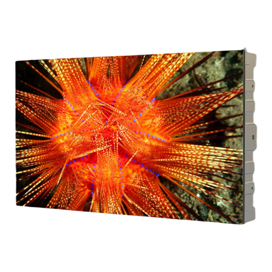
Product overview Reach new heights with Christie® Velvet® Core Series. Featuring UHD resolution, extremely high fill-factor and advanced monitoring capabilities, the Core Series is a completely certified LED display wall solution providing 24/7 operation for critical viewing environments. With front-access serviceability, remote and redundant power supply and a slim ADA-compliant design, the Core Series delivers the highest performance possible for LED displays. -
Page 6: Power Precautions
Warning! If not avoided, the following could result in death or serious injury. • After the replacement of the power supply, hi-pot and ground/earth bond tests must be performed. Only Christie qualified technicians who are familiar with the necessary precautions can perform these tests. •... -
Page 7: Terminology
Indicates the ratio between the area covered by pixels and the area not covered by pixels. Product documentation For installation, setup, and user information, see the product documentation available on the Christie Digital Systems USA Inc. website. Read all instructions before using or servicing this product. -
Page 8: Required Tools
Mounting block template (P/N: 003-006842-01) • Screws appropriate for the mounting surface. These screws are not provided. Typical LED solution Velvet LED Display System Installation and Setup Guide–Core Series 020-001713-01 Rev. 1 (08-2019) Copyright ©2019 Christie Digital Systems USA, Inc. All rights reserved. -
Page 9: Cable And Controller Layout And Design
The video source connections between the cabinets are represented by the blue line. The power connections between the cabinets are represented by the red line. Velvet LED Display System Installation and Setup Guide–Core Series 020-001713-01 Rev. 1 (08-2019) Copyright ©2019 Christie Digital Systems USA, Inc. All rights reserved. -
Page 10: E600 Controller Limitations
Menu dial for interacting with the menu Back button for exiting from the current operation or option in the menu Velvet LED Display System Installation and Setup Guide–Core Series 020-001713-01 Rev. 1 (08-2019) Copyright ©2019 Christie Digital Systems USA, Inc. All rights reserved. - Page 11 Fiber optic ports for connecting to the FE600 fiber optic extender Power Power supply port: AC 100-240V~ 50/60hz Power switch Velvet LED Display System Installation and Setup Guide–Core Series 020-001713-01 Rev. 1 (08-2019) Copyright ©2019 Christie Digital Systems USA, Inc. All rights reserved.
- Page 12 8 bit RGB444 YCbCr444 YCbCr422 YCbCr420 10 bit RGB444 YCbCr444 YCbCr422 YCbCr420 12 bit RGB444 YCbCr444 YCbCr422 YCbCr420 Velvet LED Display System Installation and Setup Guide–Core Series 020-001713-01 Rev. 1 (08-2019) Copyright ©2019 Christie Digital Systems USA, Inc. All rights reserved.
-
Page 13: Fe600 Controller Extender Interface And Ports
USB, RJ45 (with SNMP support), and USB cascading USB In OPT Output (Qty. 4) Fiber optic ports for connecting to the E600 controller Velvet LED Display System Installation and Setup Guide–Core Series 020-001713-01 Rev. 1 (08-2019) Copyright ©2019 Christie Digital Systems USA, Inc. All rights reserved. - Page 14 Power Power supply port: AC 100-240V~ 50/60hz Power switch Power supply port: AC 100-240V~ 50/60hz Velvet LED Display System Installation and Setup Guide–Core Series 020-001713-01 Rev. 1 (08-2019) Copyright ©2019 Christie Digital Systems USA, Inc. All rights reserved.
-
Page 15: Installing An Led Array From The Front
7. Install the E600 controller software (on page 26). 8. Configure the E600 controller (on page 26). The controller can be configured at any time. Before connecting the controller to the wall, Christie recommends updating the firmware and configuring the controller. -
Page 16: Installing The Mounting Pads
1. If the tiles are being mounted on an external support structure, ensure the external support structure is anchored to the wall and/or to the floor. The design and anchoring of the LED display structure is not the responsibility of Christie Digital Systems USA Inc. Contact a Christie representative for structure design options. - Page 17 • For installation onto a wooden surface:M6 wood screws—Tighten to a torque of 11.5 Nm (15.05 lbs.in) Velvet LED Display System Installation and Setup Guide–Core Series 020-001713-01 Rev. 1 (08-2019) Copyright ©2019 Christie Digital Systems USA, Inc. All rights reserved.
- Page 18 For example, install the mounting pads for the bottom left corner tile in the bottom right corner of the template hole. Velvet LED Display System Installation and Setup Guide–Core Series 020-001713-01 Rev. 1 (08-2019) Copyright ©2019 Christie Digital Systems USA, Inc. All rights reserved.
- Page 19 The corners should line up with the center of the mounting pads. The sides of the tiles should line up with the center of the mounting pads. Velvet LED Display System Installation and Setup Guide–Core Series 020-001713-01 Rev. 1 (08-2019) Copyright ©2019 Christie Digital Systems USA, Inc. All rights reserved.
-
Page 20: Mounting The Tiles
Warning! If not avoided, the following could result in death or serious injury. • External support for a display wall must be designed and implemented by a Christie qualified installer and must comply with local area regulations and safety standards. -
Page 21: Adjusting The Spacing Between Tiles
3. To test the spacing between tiles, replace the LED modules. Connecting the data source cables 1. Connect the data cables between the tiles in the array. Velvet LED Display System Installation and Setup Guide–Core Series 020-001713-01 Rev. 1 (08-2019) Copyright ©2019 Christie Digital Systems USA, Inc. All rights reserved. -
Page 22: Connecting The Power Cables
1. Connect the power cable to the next tile in the array. Power out Power in 2. Connect the cabinet power cable to the wall outlet. Velvet LED Display System Installation and Setup Guide–Core Series 020-001713-01 Rev. 1 (08-2019) Copyright ©2019 Christie Digital Systems USA, Inc. All rights reserved. -
Page 23: Installing The Led Modules
If the LED module does not fit back into place, or there is a gap between the LED modules of two tiles, adjust the spacing between the tiles. Velvet LED Display System Installation and Setup Guide–Core Series 020-001713-01 Rev. 1 (08-2019) Copyright ©2019 Christie Digital Systems USA, Inc. All rights reserved. -
Page 24: Powering On The Array
On the rear of the controller, turn the power switch to On. • On the front of the controller, press the Power button. Velvet LED Display System Installation and Setup Guide–Core Series 020-001713-01 Rev. 1 (08-2019) Copyright ©2019 Christie Digital Systems USA, Inc. All rights reserved. -
Page 25: Connecting To Video Sources
After the controller is connected and powered up, the video content is available as long as the video source is connected Velvet LED Display System Installation and Setup Guide–Core Series 020-001713-01 Rev. 1 (08-2019) Copyright ©2019 Christie Digital Systems USA, Inc. All rights reserved. -
Page 26: Installing/Accessing The E600 Controller Software
1. On the Christie website, navigate to the E600 product page. 2. Switch to the Downloads tab and click Software Downloads. 3. Download and unzip the Christie LED Control Unit E600 Software zip file. 4. Double-click the Christie Controller Software Setup <version>.exe file, and follow the on- screen instructions and install the E600 controller software. -
Page 27: Testing The Communication Between The Controller And Tiles
1. Connect a USB cable between the controller and the computer running the controller software. Velvet LED Display System Installation and Setup Guide–Core Series 020-001713-01 Rev. 1 (08-2019) Copyright ©2019 Christie Digital Systems USA, Inc. All rights reserved. -
Page 28: Locking And Unlocking The Controller
4. Launch the E600 controller software and log in as the administrator. • Click User> Advanced User Login. Velvet LED Display System Installation and Setup Guide–Core Series 020-001713-01 Rev. 1 (08-2019) Copyright ©2019 Christie Digital Systems USA, Inc. All rights reserved. - Page 29 To verify the upgrade was successful, in the top left corner of the controller display verify the version number displayed is 1.0.5.9. Velvet LED Display System Installation and Setup Guide–Core Series 020-001713-01 Rev. 1 (08-2019) Copyright ©2019 Christie Digital Systems USA, Inc. All rights reserved.
-
Page 30: Cleaning The Led Panels
2. Spin the lever to release the magnet slowly. 3. Pull the LED modules vertically off the tile. Velvet LED Display System Installation and Setup Guide–Core Series 020-001713-01 Rev. 1 (08-2019) Copyright ©2019 Christie Digital Systems USA, Inc. All rights reserved. -
Page 31: Safety
IEC 61000-4-3/EN61000-4-3 • IEC 61000-4-4/EN61000-4-4 • IEC 61000-4-5/EN61000-4-5 • IEC 61000-4-6/EN61000-4-6 • IEC 61000-4-8/EN61000-4-8 • IEC 61000-4-11/EN61000-4-11 Velvet LED Display System Installation and Setup Guide–Core Series 020-001713-01 Rev. 1 (08-2019) Copyright ©2019 Christie Digital Systems USA, Inc. All rights reserved.
Need help?
Do you have a question about the Velvet Core Series and is the answer not in the manual?
Questions and answers