Christie Core II Series Installation And Setup Manual
Led display system
Hide thumbs
Also See for Core II Series:
- Instruction sheet (9 pages) ,
- Technical reference (117 pages) ,
- User manual (48 pages)

Related Manuals for Christie Core II Series


Summary of Contents for Christie Core II Series
- Page 1 Installation and Setup Guide 020-001930-01 LED Display System Core Series II Product Name 020-001930-01 Rev. 1 (06-2021)
- Page 2 Christie's control such as maintenance of the product in proper working conditions. Performance specifications are based on information available at the time of printing. Christie makes no warranty of any kind with regard to this material, including, but not limited to, implied warranties of fitness for a particular purpose.
-
Page 3: Table Of Contents
Reviewing the tile configuration .................... 24 Setting the input resolution ....................24 Locking and unlocking the controller ..................25 LED Display System Installation and Setup Guide– Core Series II 020-001930-01 Rev. 1 (06-2021) Copyright ©2021 Christie Digital Systems USA, Inc. All rights reserved. - Page 4 LED module replacement ..................... 27 Safety..........................29 Electro-magnetic compatibility ....................29 Emissions ........................29 Immunity ........................29 LED Display System Installation and Setup Guide– Core Series II 020-001930-01 Rev. 1 (06-2021) Copyright ©2021 Christie Digital Systems USA, Inc. All rights reserved.
-
Page 5: Important Safeguards
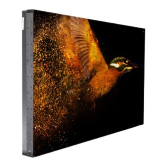
Product overview Bring overall upgrade with Christie® Core Series II. Featuring UHD resolution, extremely high fill-factor and advanced monitoring capabilities, the Core Series II is a completely certified LED display wall solution providing 24/7 operation for critical viewing environments. With front-access serviceability, remote and redundant power supply and a slim ADA-compliant design, the Core Series II delivers the highest performance possible for LED displays. -
Page 6: Power Precautions
• SHOCK HAZARD! Only use the AC power cord provided with the product or recommended by Christie. • TRIP OR FIRE HAZARD! Position all cables where they cannot contact hot surfaces, be pulled, be tripped over, or damaged by persons walking on or objects rolling over the cables. -
Page 7: Product Documentation
Indicates the ratio between the area covered by pixels and the area not covered by pixels. Product documentation For installation, setup, and user information, see the product documentation available on the Christie Digital Systems USA Inc. website. Read all instructions before using or servicing this product. -
Page 8: Required Tools
Attachment Block Template for Core Series II (P/N: 003-007100-01) • Screws appropriate for the mounting surface. These screws are not provided. LED Display System Installation and Setup Guide–Core Series II 020-001930-01 Rev. 1 (06-2021) Copyright ©2021 Christie Digital Systems USA, Inc. All rights reserved. -
Page 9: Typical Led Solution
The video source connections between the cabinets are represented by the blue line. The power connections between the cabinets are represented by the red line. LED Display System Installation and Setup Guide–Core Series II 020-001930-01 Rev. 1 (06-2021) Copyright ©2021 Christie Digital Systems USA, Inc. All rights reserved. -
Page 10: Controller Limitations
12x12 LED012 1.25 mm 16x16 LED015 1.5625mm 10x10 20x20 LED018 1.875mm 12x12 24x24 LED025 2.5mm 16x16 32x32 LED Display System Installation and Setup Guide–Core Series II 020-001930-01 Rev. 1 (06-2021) Copyright ©2021 Christie Digital Systems USA, Inc. All rights reserved. -
Page 11: E600 Controller Interface And Ports
DVI1 corresponds to Ethernet ports 1-8, and DVI2 corresponds to Ethernet ports 9-16. LED Display System Installation and Setup Guide–Core Series II 020-001930-01 Rev. 1 (06-2021) Copyright ©2021 Christie Digital Systems USA, Inc. All rights reserved. - Page 12 Menu dial for interacting with the menu Back button for exiting from the current operation or option in the menu LED Display System Installation and Setup Guide–Core Series II 020-001930-01 Rev. 1 (06-2021) Copyright ©2021 Christie Digital Systems USA, Inc. All rights reserved.
- Page 13 Fiber optic ports for connecting to the FE600 fiber optic extender Power Power supply port: AC 100-240V~ 50/60hz Power switch LED Display System Installation and Setup Guide–Core Series II 020-001930-01 Rev. 1 (06-2021) Copyright ©2021 Christie Digital Systems USA, Inc. All rights reserved.
- Page 14 8 bit RGB444 YCbCr444 YCbCr422 YCbCr420 10 bit RGB444 YCbCr444 YCbCr422 YCbCr420 12 bit RGB444 YCbCr444 YCbCr422 YCbCr420 LED Display System Installation and Setup Guide–Core Series II 020-001930-01 Rev. 1 (06-2021) Copyright ©2021 Christie Digital Systems USA, Inc. All rights reserved.
-
Page 15: Fe600 Controller Extender Interface And Ports
Fiber optic ports for connecting to the E600 controller OPT1 is used for transferring the data of port 1-8 LED Display System Installation and Setup Guide–Core Series II 020-001930-01 Rev. 1 (06-2021) Copyright ©2021 Christie Digital Systems USA, Inc. All rights reserved. - Page 16 Power Power supply port: AC 100-240V~ 50/60hz Power switch Power supply port: AC 100-240V~ 50/60hz LED Display System Installation and Setup Guide–Core Series II 020-001930-01 Rev. 1 (06-2021) Copyright ©2021 Christie Digital Systems USA, Inc. All rights reserved.
-
Page 17: Installing An Led Array From The Front
7. Install the E600 controller software (on page 7). 8. Configure the E600 controller (on page 7). The controller can be configured at any time. Before connecting the controller to the wall, Christie recommends updating the firmware and configuring the controller. - Page 18 Warning! If not avoided, the following could result in death or serious injury. • External support for a display wall must be designed and implemented by a Christie qualified installer and must comply with local area regulations and safety standards.
- Page 19 For 4x4 array For 5x5 array LED Display System Installation and Setup Guide–Core Series II 020-001930-01 Rev. 1 (06-2021) Copyright ©2021 Christie Digital Systems USA, Inc. All rights reserved.
- Page 20 1. If the tiles are being mounted on an external support structure, ensure the external support structure is anchored to the wall and/or to the floor. LED Display System Installation and Setup Guide–Core Series II 020-001930-01 Rev. 1 (06-2021) Copyright ©2021 Christie Digital Systems USA, Inc. All rights reserved.
- Page 21 The design and anchoring of the LED display structure is not the responsibility of Christie Digital Systems USA Inc. Contact a Christie representative for structure design options. 2. Determine where the mounting blocks should be installed. a. Find and mark the border of the display area with tap measure.
-
Page 22: Mounting The Tiles
Warning! If not avoided, the following could result in death or serious injury. • External support for a display wall must be designed and implemented by a Christie qualified installer and must comply with local area regulations and safety standards. -
Page 23: Adjusting The Spacing Between Tiles
Learn how to connect the data source cables. 1. Connect the data cables between the tiles in the array. LED Display System Installation and Setup Guide–Core Series II 020-001930-01 Rev. 1 (06-2021) Copyright ©2021 Christie Digital Systems USA, Inc. All rights reserved. -
Page 24: Connecting The Power Cables
2. Line up the LED module with the alignment pins in the alignment recesses, ensuring the arrow on the back of the LED module is pointing up. LED Display System Installation and Setup Guide–Core Series II 020-001930-01 Rev. 1 (06-2021) Copyright ©2021 Christie Digital Systems USA, Inc. All rights reserved. -
Page 25: Powering On The Array
Turn on each component in the array in the order below. 1. Start the computer for the video source. 2. Plug the tiles into the wall. LED Display System Installation and Setup Guide–Core Series II 020-001930-01 Rev. 1 (06-2021) Copyright ©2021 Christie Digital Systems USA, Inc. All rights reserved. -
Page 26: Connecting To Video Sources
After the controller is connected and powered up, the video content is available as long as the video source is connected. LED Display System Installation and Setup Guide–Core Series II 020-001930-01 Rev. 1 (06-2021) Copyright ©2021 Christie Digital Systems USA, Inc. All rights reserved. -
Page 27: Installing Or Accessing The E600 Controller Software
1. On the Christie website, navigate to the E600 product page. 2. Switch to the Downloads tab and click Software Downloads. 3. Download and unzip the Christie LED Control Unit E600 Software zip file. 4. Double-click the Christie Controller Software Setup <version>.exe file and follow the on- screen instructions and install the E600 controller software. -
Page 28: Testing The Communication Between The Controller And Tiles
1. Connect a USB cable between the controller and the computer running the controller software. LED Display System Installation and Setup Guide–Core Series II 020-001930-01 Rev. 1 (06-2021) Copyright ©2021 Christie Digital Systems USA, Inc. All rights reserved. -
Page 29: Locking And Unlocking The Controller
3. Connect an HDMI or Ethernet cable between the computer running the controller software and the controller. 4. Launch the 600 controller software and log in as the administrator. LED Display System Installation and Setup Guide–Core Series II 020-001930-01 Rev. 1 (06-2021) Copyright ©2021 Christie Digital Systems USA, Inc. All rights reserved. - Page 30 To verify the upgrade was successful, in the top left corner of the controller display verify the version number displayed is 1.0.5.9. LED Display System Installation and Setup Guide–Core Series II 020-001930-01 Rev. 1 (06-2021) Copyright ©2021 Christie Digital Systems USA, Inc. All rights reserved.
-
Page 31: Cleaning The Led Panels
1. Place the one end of the removal tool against the LED module. 2. Slowly attach the other end of the removal tool to the LED module. LED Display System Installation and Setup Guide– Core Series II 020-001930-01 Rev. 1 (06-2021) Copyright ©2021 Christie Digital Systems USA, Inc. All rights reserved. - Page 32 3. Pull the LED modules vertically off the tile. LED Display System Installation and Setup Guide–Core Series II 020-001930-01 Rev. 1 (06-2021) Copyright ©2021 Christie Digital Systems USA, Inc. All rights reserved.
-
Page 33: Safety
IEC 61000-4-3/EN61000-4-3 • IEC 61000-4-4/EN61000-4-4 • IEC 61000-4-5/EN61000-4-5 • IEC 61000-4-6/EN61000-4-6 • IEC 61000-4-8/EN61000-4-8 • IEC 61000-4-11/EN61000-4-11 LED Display System Installation and Setup Guide– Core Series II 020-001930-01 Rev. 1 (06-2021) Copyright ©2021 Christie Digital Systems USA, Inc. All rights reserved. - Page 34 Corporate offices Worldwide offices United States (Arizona) Africa Columbia Mexico Christie Digital Systems USA, Inc. ph: 602 943 5700 ph: +27 (0) 11 510 0094 ph: +52 55 4744 1790 ph: 714 236 8610 ph: +57(318) 447 3179 Singapore Australia...
Need help?
Do you have a question about the Core II Series and is the answer not in the manual?
Questions and answers