
Related Manuals for Aerotech Ndrive HL


Summary of Contents for Aerotech Ndrive HL
- Page 1 (217) 352-9330 | Click HERE Find the Aerotech NDrive CP10 at our website:...
- Page 2 Ndrive HL User’s Manual P/N: EDU176 (Revision: 1.08b) Dedicated to the Science of Motion Aerotech, Inc. 101 Zeta Drive, Pittsburgh, PA, 15238 Phone: 412-963-7470 Fax: 412-963-7459 www.aerotech.com Artisan Technology Group - Quality Instrumentation ... Guaranteed | (888) 88-SOURCE | www.artisantg.com...
- Page 3 January 4, 2006 1.08b October 31, 2007 Product names mentioned herein are used for identification purposes only and may be trademarks of their respective companies. © Aerotech, Inc. 2005-2007 Artisan Technology Group - Quality Instrumentation ... Guaranteed | (888) 88-SOURCE | www.artisantg.com...
-
Page 4: Table Of Contents
Ndrive HL User’s Manual Table of Contents TABLE OF CONTENTS CHAPTER 1: INTRODUCTION ..........1-1 1.1. Feature Summary ..............1-2 1.2. Connection Overview..............1-3 1.3. Ndrive HL Block Diagram............1-4 1.4. Ordering Information ..............1-5 1.5. Electrical Specifications ............1-6 1.6. Mechanical Specifications............1-9 1.7. Environmental Specifications..........1-10 CHAPTER 2: INSTALLATION and CONFIGURATION .... - Page 5 Handwheel Interface ..............5-9 CHAPTER 6: TROUBLESHOOTING ........6-1 6.1. Problems, Causes, and Solutions..........6-1 6.2. Ndrive HL Control Board Test Points ........6-2 6.3. Ndrive HL Control Board Assembly .......... 6-3 6.4. Ndrive HL Motor Power Board Assembly ......... 6-5 6.5.
- Page 6 Ndrive HL User’s Manual List of Figures LIST OF FIGURES Figure 1-1. Ndrive HL Networked Digital Drive ...........1-1 Figure 1-2. Ndrive HL Hardware ..............1-3 Figure 1-3. Ndrive HL Functional Diagram..........1-4 Figure 1-4. Ndrive HL Dimensions ..............1-9 Figure 2-1. -AUXPWR Option ..............2-2 Figure 2-2.
- Page 7 Optimized Resolver Feedback Configuration ......4-29 Figure 5-1. Joystick Interface ..............5-5 Figure 5-2. Single Axis Joystick Interface to J205 of the Ndrive HL ... 5-6 Figure 5-3. Single Axis Joystick Interconnect to J205 of the Ndrive HL....................5-7 Figure 5-4.
- Page 8 Table 1-1. Ndrive HL Models and Voltage Configurations......1-5 Table 1-2. Electrical Specifications ............1-6 Table 1-3. Ndrive HL Series Amplifier Current Limitations ......1-8 Table 2-1. Optional Aux Supply AC Input (for external E-Stop)....2-2 Table 2-2. Main Supply AC Power Input Connections.......2-3 Table 2-3.
- Page 9 Ndrive HL Motor Power Board Jumper Selections ....6-6 Table 6-5. Ndrive HL Motor Power Board Fuse Information...... 6-6 Table 6-6. Ndrive HL Motor Power Board Test Point Information ..... 6-6 Table 6-7. Jumper Selections (Line Voltage) on Power Supply Board..................6-7 Table 6-8.
- Page 10 Control and Emergency Stop requirements are to be determined and provided by the end user. • Wire and cabling provided with the unit meet Aerotech’s electrical and listed environmental requirements. The end user must meet the final requirements. Pittsburgh, PA David F.
- Page 11 Install a snap-on Ferrishield ferrite attenuator, P/N SS28B2034, on the FireWire cable at the unit. • Use a FireWire card with inductive common mode filters, such as the Aerotech NFIRE-PCI or Siig NN-403P12. These modifications may not be necessary in the final installation of the product. Since the unit is a component, designed to be integrated with other electronics, EMC testing must be conducted on the final product configuration.
-
Page 12: Chapter 1: Introduction
I/O solutions. Additionally, one 18 bit analog output and one 16 bit analog input is standard. The Ndrive HL also features an optional on-board brake relay, programmable resolution multiplication up to x65,536, with a 200 kHz maximum amplified sine wave input frequency, and up to three-axis Position Synchronized Outputs (laser firing). -
Page 13: Feature Summary
Introduction Ndrive HL User’s Manual 1.1. Feature Summary • Software configurable for brush (torque/current and tachometer mode) and brushless motor operation • Bipolar 40 or 80 VDC bus power supply • Fully isolated power stage • 5 VDC, 500 mA user output power for encoder and Hall effect signals, etc. -
Page 14: Connection Overview
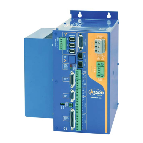
1.2. Connection Overview The Ndrive HL consists of a power connection (motor power and input power), three FireWire ports, an optional Ethernet connection, an RS-232/RS-422 connector, LED indicator lamps and two D-style connectors for Auxiliary I/O (15 and 26 pin) and Motor Feedback (25 pin). -
Page 15: Ndrive Hl Block Diagram
Introduction Ndrive HL User’s Manual 1.3. Ndrive HL Block Diagram The standard package includes the bus power supply that operates from standard AC line voltage (100/115/208/230 factory configured). The power supply is included with the standard package for off-line operation without the need for an isolation transformer. -
Page 16: Ordering Information
Ndrive HL User’s Manual Introduction 1.4. Ordering Information The Ndrive HL is available in three base models with continuous power, ranging from 675 to 1,350 watts. A list of these models, and the available voltage configurations, are shown in Table 1-1 Table 1-1. -
Page 17: Electrical Specifications
Introduction Ndrive HL User’s Manual 1.5. Electrical Specifications The electrical specifications for the Ndrive HL are listed in Table 1-2. Table 1-2. Electrical Specifications Description Units 20-40 10-40 10-80 100, 115, 200, 230 Main Supply Input Voltage (model dependent) Main Supply Input Frequency... - Page 18 Auxiliary Power 5V-Pin 3: On board 5V power supply. Pin 3 is intended for Outputs (AL1, AL2) powering an encoder. Ndrive HL can supply up to 500 mA of current total to user devices. Output short circuit Peak over current...
-
Page 19: Table 1-3. Ndrive Hl Series Amplifier Current Limitations
Introduction Ndrive HL User’s Manual Table 1-3. Ndrive HL Series Amplifier Current Limitations Ndrive HL10-40 Ndrive HL10-40 Ndrive HL20-40 Ndrive HL20-40 Ndrive HL10-80 Ndrive HL10-80 = 25 = 50 = 25 = 50 = 25 = 50 ambient ambient ambient... -
Page 20: Mechanical Specifications
23.8 [0.94] 2.3 [0.09] 4.7 [0.19] 230.1 [9.06] 255.0 [10.04] Figure 1-4. Ndrive HL Dimensions The Ndrive HL case temperature may exceed 75°C in some applications. www.aerotech.com Artisan Technology Group - Quality Instrumentation ... Guaranteed | (888) 88-SOURCE | www.artisantg.com... -
Page 21: Environmental Specifications
Introduction Ndrive HL User’s Manual 1.7. Environmental Specifications The environmental specifications for the Ndrive HL are listed below. • Ambient Temperature: Operating - 5° - 40°C (41° - 104°F) Storage - -20 – 70°C (-4 – 158°F) Maximum relative humidity is 80% for temperatures up •... -
Page 22: Chapter 2: Installation And Configuration
Ndrive HL User’s Manual Installation and Configuration CHAPTER 2: INSTALLATION and CONFIGURATION This section covers the hardware configurations using the switches, jumpers, connectors, and power connections when used with a brush or brushless motor. Wiring, grounding, shielding techniques, and the motor phasing process are also covered. -
Page 23: Power Connections
2.2. Power Connections The Ndrive HL may powered by one or two separate AC voltages. One for motor bus power and optionally a second for control power, as described in the following two sub- sections. If the optional control power input is present, it must be powered. -
Page 24: Motor Power Connections
Ndrive HL User’s Manual Installation and Configuration 2.2.2. Motor Power Connections Input power to the Ndrive HL is made at the AC1 and AC2 terminals with earth ground connected to (ground). The motor frame and shield connect to (ground) as well. -
Page 25: Motor Connections (Tb101)
Installation and Configuration Ndrive HL User’s Manual 2.2.3. Motor Connections (TB101) The three-phase motor terminal connections are made at connections A, B, C and optionally at RT. The RT connection is only used for brushless motors having a fourth motor lead, as in a Wye configuration. Motor Connections ØA, ØB, ØC and its Protective Ground should be made with 1.62814 mm (#14 AWG) wire rated at 300 V. -
Page 26: Emergency Stop Sense Input (Tb201)
Ndrive HL User’s Manual Installation and Configuration 2.3. Emergency Stop Sense Input (TB201) This input is intended to be activated by an external fail-safe emergency stop circuit. It is not intended to be an emergency stop circuit in itself. It is scaled for an input voltage of 5-24 volts. -
Page 27: Typical Estop Interface
Ndrive HL User’s Manual 2.3.1. Typical ESTOP Interface The user may connect an emergency stop circuit to the Ndrive HL. It will disable power to the motor by removing power to the power stage of the drive, while maintaining power to the control section, as shown in the following Figure 2-4. -
Page 28: Motor And Feedback Connections
Installation and Configuration 2.4. Motor and Feedback Connections The Ndrive HL can be integrated into a system using three basic configurations: DC Brush (Velocity and Torque mode), brushless or stepper motors. Brush and brushless motors may have two feedback devices. -
Page 29: Dc Brush Motor With Tachometer Feedback Configuration
The DC brush motor configuration is shown in Figure 2-6. See section 2.5.1. for the correct encoder phasing information if Aerotech’s standard cabling is not used. The tachometer may be connected to TB302 or J205 as shown in the picture below. Note, that tachometer feedback uses analog input 0, so it may not be used when tachometer feedback is used. -
Page 30: Brushless Motor Configuration
Ndrive HL User’s Manual Installation and Configuration 2.4.3. Brushless Motor Configuration This mode is used with a brushless motor only. See section 2.5., if Aerotech’s standard cabling is not used, for information on correctly phasing the motor, encoder and Hall feedback devices. - Page 31 When configuring the Ndrive HL to run a non-Aerotech brushless motor, the motor leads (A, B and C on TB101) must be correctly connected for proper operation. If an Aerotech motor is used with Aerotech provided cabling, no motor phasing process is required.
-
Page 32: Figure 2-8. Hall-Effect Feedback Connections
Ndrive HL User’s Manual Installation and Configuration 2.4.3.2. Brushless Motor Hall-Effect Feedback Connections The Hall-Effect feedback signals on an AC brushless motor are correctly phased when the hall states correspond to the states at each of the electrical angles shown in Figure 2- 10 The hall states, which correspond to the electrical angles are indicated in Figure 2-10 A “0”... - Page 33 Installation and Configuration Ndrive HL User’s Manual 2.4.3.3. Hall-Effect Phasing For an AC brushless motor with an unknown phase/hall sequence, one of two simple tests can be performed on the motor to determine the proper connections to the Ndrive Be sure to first configure the axis parameters before running the A3200\Programs\Samples\MsetDebug.Pgm.
-
Page 34: Figure 2-10. Motor Phasing
Ndrive HL User’s Manual Installation and Configuration Figure 2-10. Motor Phasing www.aerotech.com 2-13 Artisan Technology Group - Quality Instrumentation ... Guaranteed | (888) 88-SOURCE | www.artisantg.com... -
Page 35: Stepper Motor Configuration
Installation and Configuration Ndrive HL User’s Manual 2.4.4. Stepper Motor Configuration This mode is used with a stepper motor only. See section 2.5.1., if Aerotech’s standard cabling is not used for information on correctly phasing the motor feedback devices. Figure 2-11. -
Page 36: Encoder Feedback Connections
One encoder feedback device must be used for all motor types, except for stepper motors. Each of the two encoder channels in the Ndrive HL, accept a differential line driver encoder, or with the -MXH option, the primary encoder channel, J207 accepts an analog sine wave encoder. -
Page 37: Encoder Phasing
Installation and Configuration Ndrive HL User’s Manual 2.5.1. Encoder Phasing Figure 2-13 illustrates the required encoder phasing for clockwise motor rotation, or positive forcer movement, through the stationary magnet track. If the motor is not visible, or maybe not be manually moved by hand, it maybe actively driven open loop, under program control, via the A3200\Programs\Samples\MsetDebug.Pgm. -
Page 38: End Of Travel (Eot) Limit Input Connections
If the EOT limits are reversed, swap the connections to the CW and CCW inputs at the J207 connector of the Ndrive HL. The logic level of the EOT limit inputs may be viewed on the Diagnostic tab of the Nstat utility, as shown in Figure 2-15. -
Page 39: Communication Channel Settings
“Axis“ menu in Nparam, they will be the parameters in the first column. The Ndrive HL configured as Row 2 indicates below, will be configured by the axis parameters in column 2 of the Nparam utility, etc. -
Page 40: Connecting Multiple Ndrive Hls
Ndrive HL User’s Manual Installation and Configuration 2.8. Connecting Multiple Ndrive HLs Following are two interconnection diagrams and a chart showing the part numbers of the FireWire Bus PCI card and the various interconnect cables and their part numbers. Table 2-6. -
Page 41: Pc Configuration And Operation Information
The Getting Started Guide (PN: EDU175), included with the Nmotion SMCs software package, provides a quick start guide with basic information. The Nview help included with the software provides additional information for configuring the Ndrive HL to the PC as well as information on hardware requirements, getting started, utilities and system operation, and on using the Nview HMI user application. -
Page 42: Chapter 3: Technical Details
Ndrive HL User’s Manual Technical Details CHAPTER 3: TECHNICAL DETAILS 3.1. Auxiliary I/O Connector (J205) The J205, Auxiliary I/O connector provides 1 analog and 6 digital inputs, 1 analog and 4 digital outputs and a secondary bi-directional RS-422 line driver encoder interface. See the following sub-sections for details on each type of signal within the J205 connector. - Page 43 EIZ00294 TRW D-20419-16 All of the external power provided by the Ndrive HL to the user is limited to 500 mAmps and protected by a re-settable semiconductor fuse. Should an over-current condition occur, the device will open to protect against the overload. To reset the over-current device, remove the overload condition.
-
Page 44: Secondary Encoder Channel (J205)
Ndrive HL User’s Manual Technical Details 3.1.1. Secondary Encoder Channel (J205) The encoder channel can be used as an input for master/slave operation (handwheel) or for dual feedback systems or for an encoder input/output for multi-axis laser firing (see Chapter 4 for more information). The EncoderDivider axis parameter configures the input/output state of this encoder channel. -
Page 45: User Outputs 8-11 (J205)
Technical Details Ndrive HL User’s Manual 3.1.2. User Outputs 8-11 (J205) All outputs (Figure 3-2) are rated for 40 volts DC and 80 mAmps per channel. Power dissipation may not exceed 90 mWatts per channel. Figure 4-10 illustrates how to connect to an output in current sinking mode. -
Page 46: User Inputs 8-11 (J205)
Ndrive HL User’s Manual Technical Details 3.1.3. User Inputs 8-11 (J205) All inputs (Figure 3-3), including the high-speed inputs, are scaled for an input voltage of 5-24 volts DC. A higher input voltage requires adding external series resistors to limit the current to 20 milliamps. -
Page 47: High Speed User Inputs 12-13 (J205)
Technical Details Ndrive HL User’s Manual 3.1.4. High Speed User Inputs 12-13 (J205) All inputs (Figure 3-3), including the high-speed inputs, are scaled for an input voltage of 5-24 volts DC. A higher input voltage requires adding external series resistors to limit the current to 20 milliamps. -
Page 48: Position Synchronized Output (Pso) / Laser Firing
The Ndrive HL offers three levels of laser firing, single axis (std.) and two and three axis. Trigger signals may be derived from the primary encoder channel, secondary encoder channel, either of the two optional SSI Net ports or a software trigger. - Page 49 Technical Details Ndrive HL User’s Manual The trigger condition may be a software trigger under program control, various other hardware triggers, or most typically a user-defined change in vectorial position, on one to three axes. This vectorial position change is monitored via hardware, allowing an output pulse to be generated in less than 275 nanoseconds (200 nsec.
-
Page 50: Figure 3-4. Advanced 1 - 3 Axis Firing
Ndrive HL User’s Manual Technical Details Figure 3-4. Advanced 1 - 3 Axis Firing The window modes allow firing to occur, or be enabled, based upon axes being within a user-defined window. This window may be one or two-dimensional. The ± and Enter/Exit Detection block within the block diagram is used to prevent false triggering due to one bit dither on an axis, etc. -
Page 51: Figure 3-5. Data Capture/Data Update Modes
Technical Details Ndrive HL User’s Manual These Capture/Update modes, share four FIFO's (queue's) with Window 1 and Window 2, preventing the window-firing modes from being used with the Capture/Update mode. Using a queue from a window, precludes using that window (1 or 2) for firing, however, queues from window 1 may be used for data capture/update mode, while queues from window 2 may be used for window firing purposes. -
Page 52: Single Axis Laser Firing
Ndrive HL User’s Manual Technical Details 3.2.1. Single Axis Laser Firing Single axis firing requires no additional encoder signals and is capable of tracking the axis position at up to a 20 MHz. tracking rate (50 nsec. minimum edge separation). It may be programmed to fire from any available encoder source, see Table 3-9. -
Page 53: Motor Feedback (J207)
ECK00656 Amphenol P/N 17-1726-2 All of the external power provided by the Ndrive HL to the user is limited to 500 mAmps and protected by a re-settable semiconductor fuse. Should an over-current condition occur, the device will open to protect against the overload. To reset the over-current device, remove the overload condition. -
Page 54: End Of Travel Limit Inputs
Ndrive HL User’s Manual Technical Details 3.3.1. End of Travel Limit Inputs Two of the three limit inputs are end-of-travel sensing (CW Limit and CCW Limit) while the third is a reference limit (Home Limit). All of the end-of-travel limit inputs accept 5- 24 volt DC logic signals. -
Page 55: Hall-Effect And Thermistor Inputs
Technical Details Ndrive HL User’s Manual 3.3.2. Hall-Effect and Thermistor Inputs The Hall-Effect switch inputs are highly recommended for AC brushless motor commutation but not absolutely required, see the Nview help for more information on axis configuration. The Hall-effect inputs accept 5-24 volt DC logic signals. The pin assignment for the connector is shown in the table below. -
Page 56: Brake Output
* Total user +5 V power is limited to 500 mA, by an internal re-settable semiconductor fuse. All external power provided by the Ndrive HL to the user is protected by a re-settable semiconductor fuse. Should an over-current condition occur, the device will open to provide protection against the overload. -
Page 57: Figure 3-9. Line Driver Encoder Interface - Standard (J207)
An analog encoder is used with the MXH option; see Figure 3-10 for more information. Figure 3-9. Line Driver Encoder Interface – Standard (J207) The Ndrive HL is factory configured for either a square wave differential encoder (default), OR an analog encoder (MXH options). 3-16 www.aerotech.com... - Page 58 LED’s will alternate between the two patterns shown to the lower right. The Ndrive HL contains digital potentiometers to adjust the gain, offset and phase balance of the analog Sine and Cosine inputs. The digital potentiometer settings are controlled by the CfgFbkEncCosGain, CfgFbkEncCosOffset, CfgFbkEncPhase, CfgFbkEncSineGain, CfgFbkEncSineOffset axis parameters.
- Page 59 Technical Details Ndrive HL User’s Manual Table 3-17. MXH Option Specifications Applicable only when signals are output via the SSI Net CfgFbkEncMult- (1,2) Total FactorMXH Axis Clock Max Input Edge Min Pulse Multiplication Parameter Freq (kHz) Separation (µs) Width (µs) Freq.
-
Page 60: Figure 3-10. Optional Mxh Analog Encoder Interface (J207)
Ndrive HL User’s Manual Technical Details Figure 3-10. Optional MXH Analog Encoder Interface (J207) www.aerotech.com 3-19 Artisan Technology Group - Quality Instrumentation ... Guaranteed | (888) 88-SOURCE | www.artisantg.com... -
Page 61: Rs-422 Port (J206)
PC requires only a standard 9-pin RS-232C interconnection cable (not a null modem). Currently, the RS-232C port serves only as a secondary means to upgrade the firmware in the Ndrive HL, which is done primarily through the FireWire port. Table 3-18. -
Page 62: Figure 3-11. Rs-232/Rs-422 Connector (J206)
Ndrive HL User’s Manual Technical Details Figure 3-11. RS-232/RS-422 Connector (J206) www.aerotech.com 3-21 Artisan Technology Group - Quality Instrumentation ... Guaranteed | (888) 88-SOURCE | www.artisantg.com... -
Page 63: Firewire Bus (J201, J202, J203)
Ndrive HLs together or with other devices such as the Ndrive CP, HP, Nstep, Nservo or Npaq. The FireWire bus power is independent of the Ndrive HL power. Should a drive fail, communication will be maintained with the other devices. -
Page 64: Voltage-To-Current Mode Operation
Figure 3-12. Normal Operation The Voltage-to-Current mode of the Ndrive HL allows for a connection to a host controller that outputs ±10V DC as a torque (current) command. In this mode, a connection to the fire wire is not required (synchronization is performed internally), except for parameter configuration. -
Page 65: Parameter Setup And Hardware Configuration
FLASHWRITE 1 0 0 This will save the current system configuration into the flash memory on the Ndrive HL. To enter the voltage-to-current mode, power down the Ndrive and set DIP switches #6 and #7 to the OFF position. When the unit is powered on again, it will auto-boot into the voltage-to-current mode. -
Page 66: Operation
-IOPSO option board or the J205 connector. To emulate a standalone drive, the Ndrive HL also uses Input #8 (least-significant input bit on the J205 connector) as a drive enable input, and Output #8 (least-significant output bit on the J205 connector) as a fault output indicator. - Page 67 Technical Details Ndrive HL User’s Manual 3-26 www.aerotech.com Artisan Technology Group - Quality Instrumentation ... Guaranteed | (888) 88-SOURCE | www.artisantg.com...
-
Page 68: Options
Ndrive HL User’s Manual Options CHAPTER 4: OPTIONS 4.1. –IOPSO and –IOPSOH Option Boards See the following sections for details on the connector pin assignment and technical information for the –IOPSO and –IOPSOH options. Figure 4-1. –IOPSO Option Board Location The –IOPSO expansion board has 8 opto-isolated inputs (sinking or sourcing) and 8... -
Page 69: Brake Configuration Jumpers
Options Ndrive HL User’s Manual The -IOPSOH expansion board has 8 opto-isolated inputs (sinking or sourcing) and 8 outputs (sinking or sourcing ) rated at 1 A per channel, two 18-bit analog outputs, two 16-bit differential analog inputs, SSI Net, absolute encoder interface and brake relay, and includes HCPL2601 opto-isolator. -
Page 70: Analog Outputs (Tb301)
Ndrive HL User’s Manual Options 4.1.2. Analog Outputs (TB301) Both analog outputs are driven by an 18-bit AD1868 digital to analog converter and buffered by TL084 op-amps, producing a single-ended output voltage in the range of ±10 volts. This produces a resolution of 76.3 uVolts per bit of the D/A. The output current is limited to less than 50 mA. -
Page 71: Brake / Relay (Tb301)
Options Ndrive HL User’s Manual 4.1.3. Brake / Relay (TB301) The relay output is typically used to automatically drive a fail-safe brake on a vertical axis, however, it may also be used as a general purpose relay. See the BrakeOnDriveDisable axis parameter for information on activating the brake output automatically, or the BRAKE command for manually toggling the output, both in the Nview HMI help. -
Page 72: Figure 4-5. Brake Connected To Tb301
Ndrive HL User’s Manual Options Table 4-5. Brake / Relay Connector Pin Assignment (TB301) Pin # Label Description In/Out/Bi. Relay-N.C. (Brake) Relay Output Normally Closed Contact Output Relay-Com. (Brake) Relay Output Common Contact Output (Brake) Relay Output Normally Open Contact Relay-N.O. - Page 73 Options Ndrive HL User’s Manual Figure 4-6 is an example of a 24 VDC Brake connected to the Motor Feedback connector (J207) In this example the external 24 VDC power source is connected to TB301. Also note that JP1-A is set 1-2 and JP1-B is set 3-4.
-
Page 74: Figure 4-7. Diode Suppression For Dc Brake Systems
Ndrive HL User’s Manual Options Step #3 Suppression and Snubber Requirements Due to the inductive effects of the brake, suppression and/or snubber, components are needed to reduce arching and prevent damage to the Brake Relay contacts. Suppression can also reduce the electrical noise that is emitted when the circuit is switched off. -
Page 75: Figure 4-8. Rc Suppression For Dc Brake Systems
Options Ndrive HL User’s Manual Example #3: Figure 4-8 is a suppression circuit that can be used for both AC and DC circuits. In this method, a resistor, capacitor and a varistor are used across the load (see Figure 4-8). In some cases, better results are obtained by installing the suppression devices across the relay contacts. -
Page 76: Analog Inputs (Tb302)
Ndrive HL User’s Manual Options 4.1.4. Analog Inputs (TB302) Both analog inputs are differential, buffered by a precision unity gain differential INA105 amplifier and converted to digital by a 16-bit ADS8320 analog to digital converter allowing an input voltage in the range of ±10 volts. This produces a resolution of 305 uVolts per bit of the A/D. -
Page 77: User Power Connector (Tb303)
Ndrive HL User’s Manual 4.1.5. User Power Connector (TB303) This connector provides access to the Ndrive HL’s internal power supply, which may be used to power external devices (500 mAmps maximum). It also provides a connection to power the opto-isolated PSO output (see Section 4.1.8., Figure 4-15). -
Page 78: Figure 4-10. Connecting Outputs In Current Sinking Mode
Ndrive HL User’s Manual Options Table 4-10. Output Specifications (TB304) Specification -IOPSO Value -IOPSOH Value Maximum Power Dissipation 90 mWatts / Channel 600 mWatts / Channel Maximum Voltage 40 Volt Maximum 24 Volt Maximum Maximum Sink/Source Current 80 mAmps / Channel... -
Page 79: Opto-Isolated Inputs (Tb305)
Options Ndrive HL User’s Manual Suppression diodes must be installed on outputs that are used to drive relays or other inductive devices to protect the output devices from being damaged by the inductive spikes that occur when the device is turned off. Suppressor diodes can be installed on all outputs to provide greater protection. -
Page 80: Figure 4-12. Inputs Connected In Current Sourcing Mode
Ndrive HL User’s Manual Options Figure 4-12. Inputs Connected in Current Sourcing Mode Figure 4-13. Inputs Connected in Current Sinking Mode www.aerotech.com 4-13 Artisan Technology Group - Quality Instrumentation ... Guaranteed | (888) 88-SOURCE | www.artisantg.com... -
Page 81: Pso / Absolute Encoder Interface (J301)
* Users should use the opto-isolated output where possible to maintain the isolation between the Ndrive HL and the laser. This prevents noise and current spikes (from laser firing pulses) from being conducted through the Ndrive HL! This requires the user to power the opto-isolator at TB303 (see Section 4.1.5. -
Page 82: Figure 4-14. Absolute Encoder Interface (J301)
Ndrive HL User’s Manual Options Table 4-14. Laser Output Opto-Isolator Specifications M12 Device (Option#) Nominal Propagation Power Supply Output (Figure 4-15) Frequency Delay (Typ.) Voltage Current Sink *HCPL-2601 5 MHz .05 us. 5 VDC 10 mA (–PSOOPTO1 option, std) 6N136 750 KHz .45 us. -
Page 83: Figure 4-15. Pso Interface (J301 And Tb303)
Options Ndrive HL User’s Manual Figure 4-15. PSO Interface (J301 and TB303) Output 11 and the Auxiliary Marker on J205 (pins 19 and 20) may also be defined as the PSO Laser Firing output via the PSOCONTROL command. See Section 3.2 for connection and other information. -
Page 84: Ssi Net (2 Channel) (J302, J303)
Section 4.1.8.). The signals from these ports will be the same as the differential line driver encoder signal input to the Ndrive HL, unless the –MXH option is present. The signal output, when the –MXH option is present, will be of a pulse width determined by the –MXH clock frequency, as indicated in Table 3-17. - Page 85 Options Ndrive HL User’s Manual Figure 4-17. J301/J302/J303 4-18 www.aerotech.com Artisan Technology Group - Quality Instrumentation ... Guaranteed | (888) 88-SOURCE | www.artisantg.com...
-
Page 86: Dualpso And -Triplepso Laser Firing Options
If the SSI Net is used it requires a cable (see Table 4-16 and Figure 4-18) from J302 to J302 of each Ndrive HL (J302 to J302 or J303 to J303 of the other Ndrive HL, both connectors each have the same two SSI Net ports present on each connector. -
Page 87: Pso Tracking Rate Configuration
Options Ndrive HL User’s Manual Table 4-16. SSI Net Cable Part Numbers Part # Description NConnect-SSINet-4500 4.5 M (15 FT) SSI Net Cable NConnect-SSINet-3000 3.0 M (10 FT) SSI Net Cable NConnect-SSINet-1500 1.5 M (5 FT) SSI Net Cable NConnect-SSINet-900 0.9 M (3 FT) SSI Net Cable... - Page 88 EXAMPLE: An application uses a 4um linear encoder with an MXH option on an Ndrive HL. It is desired to move the motor at a maximum speed of 200mm/second and track using the –DUALPSO or –TRIPLEPSO option.
-
Page 89: Enet (Ethernet) Option J204
Options Ndrive HL User’s Manual 4.3. –ENET (Ethernet) Option J204 The optional Ethernet port provides connectivity to a 10/100 Base-T ModBus TCP network, or the PC’s Ethernet port may be used. This is typically used for adding analog and digital I/O to the controller. See the Ethernet I/O help on the Windows Start bar on the Automation 3200 menu. -
Page 90: Rdp Resolver Input
Ndrive HL User’s Manual Options 4.4. –RDP Resolver Input The optional resolver input provides two industry standard resolver or Inductosyn channels, which may each be used as a feedback device. Each may be separately configured for resolver or inductosyn input, as shown in Table 4-21. The standard reference output frequency is 10 kHz, optionally it may be configured as 5 or 7.5 kHz at... -
Page 91: Resolver/Inductosyn Setup
Options Ndrive HL User’s Manual Table 4-22. Resolver Test Points Test Point Number Description Signal Common TP10 Sine input Channel 1 TP11 Cosine input Channel 1 TP12 Reference signal Channel 1 TP20 Sine input Channel 2 TP21 Cosine input Channel 2... -
Page 92: Figure 4-22. Analog Output Connector (Tb301)
Some Aerotech systems may have an optional pre- amplifier board. This may be installed within the mechanics itself, as is the case with an Aerotech AOM360D optical mount. If so, the first step is to adjust the P1 potentiometer on the pre-amplifier board to equalize the Sine and Cosine feedback signals to the same amplitude. - Page 93 Using the Encoder Feedback Configuration Utility to set up a resolver/inductosyn The RDP option of the Ndrive HL can be optimally aligned quickly, using the Encoder Feedback Configuration utility within the NScope.exe utility. When the Ndrive HL is configured for Resolver Feedback (via the CfgFbkPosType axis...
-
Page 94: Figure 4-23. Resolver Located At Maximum Of Sin Signal
Ndrive HL User’s Manual Options Adjusting the CfgFbkRDCosPhase axis Parameter: After starting the Encoder Feedback Configuration utility, make sure the proper axis is selected and then start collecting data continuously. Set the CfgFbkRDGain axis parameter to 0 to minimize the gain. This can be done through the Ndebug.exe utility. - Page 95 Options Ndrive HL User’s Manual Figure 4-24. Rotating the Resolver (to see a circle) For this to function you MUST have the proper jumper set to 2-3 for this channel and the bit in the CfgFbkRDConfig axis parameter set to 1. Otherwise, erratic results may occur.
-
Page 96: Figure 4-25. Optimized Resolver Feedback Configuration
Ndrive HL User’s Manual Options Figure 4-25. Optimized Resolver Feedback Configuration 4.4.1.3. Configuring the Commutation Initialization The commutation of brushless motors with resolver feedback may be initialized two ways. The first method uses the number of motor pole pairs combined with the maximum resolution of the R/D board to determine an initial commutation position. - Page 97 Finding the Proper Commutation Offset in R/D Auto-Configuration Mode The R/D Auto-Configuration mode assumes that the zero crossing of the R/D Converter is aligned with the 0 angle of commutation on the Ndrive HL. Therefore, to determine the commutation offset angle, perform the following steps:...
-
Page 98: Accessories
5.1. Standard Interconnection Cables The following three Tables show a summary of the standard cables used for interconnecting various items to the Ndrive HL. To identify your cable or for a wiring/assembly drawing, see your software CD ROM. Table 5-1. -
Page 99: Table 5-2. Combined Motor & Feedback Cables
Accessories Ndrive HL User’s Manual Table 5-2. Combined Motor & Feedback Cables Ndrive HL Part Number (s) Description Stage/Motor C18982-xx BL MTR & FB-25DU FL-25DU-MAX107DM BFMCDNT-yy Obsolete Used On: Motor Output Any brushless motor stage having a single 25 pin “D” style connector for motor power, encoder, limits and halls. -
Page 100: Table 5-3. Individual Motor Cables
Ndrive HL User’s Manual Accessories Table 5-3. Individual Motor Cables Ndrive HL Part Number (s) Description Stage/Motor C15805-xx BL MTR-FL-4MS-MAX450DM PMCNT-yy Obsolete Used On: Any brushless motor stage having a 4 pin “MS”style connector for motor power. BM/BMS motors (with -MS option) -
Page 101: Table 5-4. Individual Feedback Cables
Accessories Ndrive HL User’s Manual Table 5-4. Individual Feedback Cables Ndrive HL Part Number (s) Description Stage/Motor C16501-xx BL FB-25DU-25DU-MAX120DM C16505-xx BL FB-25DU-25DU-MAX240DM BFCMX-yy Obsolete Used On: Any brushless motor stage having a 25 pin “D” style connector for encoder, limits, halls and brake. -
Page 102: Joystick Interface
5.2. Joystick Interface The user may connect an Aerotech JI (not JBV, or JP4) joystick or their own joystick and switches to the Ndrive HL (Refer to Figure 5-1). The joystick interlock input must be set to the logic low state to indicate the joystick is connected. The zero velocity null-point for each joystick is approximately 2.5 volts. - Page 103 Accessories Ndrive HL User’s Manual A standard Aerotech JI joystick may be connected to J205 of the Ndrive HL as a single axis joystick via the following cable, shown below (Figure 5-2 and Figure 5-3). Figure 5- 2 indicates the required cable and Figure 5-3 indicates the interconnection of the joystick to the Ndrive HL.
-
Page 104: Figure 5-1. Joystick Interface
Single Axis Joystick Interconnect to J205 of the Ndrive HL A standard Aerotech JI joystick may be connected to the I/O on the –IOPSO option via the following cable for a two-axis joystick. Figure 5-4 indicates the required cable and the Figure 5-5 indicates the interconnection of the joystick to the Ndrive HL. -
Page 105: Figure 5-5. Two-Axis Joystick Connection To The I/O On The -Iopso Option
1. USING C19791-XX CABLE WILL PROVIDE 2 AXES OF SLEWING. REQUIRES THE Ndrive HL TO HAVE THE "IOPSO" OPTION INSTALLED. Ndrive HL 2. THE JI JOYSTICK MUST BE USED WITH THE Ndrive HL. JBV OR JP4 Joystick Interface JOYSTICK VERSIONS ARE NOT COMPATIBLE. -
Page 106: Handwheel Interface
See the Nview HMI help for information on enabling the handwheel via software commands. The handwheel may be connected to J205 of the Ndrive HL as shown in Figure 5-6 below, or the I/O available on the –IOPSO option, shown in subsequent Figures. -
Page 107: Figure 5-8. Bba32 Interface Used To Connect A Handwheel With Flying Leads (No Connector)
Accessories Ndrive HL User’s Manual 10 FT. OR AR. LENGTH 1. INSTALL LABEL TO BACK OF HANDWHEEL Ndrive HL J205 HANDWHEEL BBA32 MODEL: HWA32-FLY-XX XX = CABLE LENGTH IN DECIMETERS 630B1983-1 REV. - SUMTAK S/N: XXXXXX XXXXXX = WORK ORDER NUMBER... -
Page 108: Troubleshooting
6.1. Problems, Causes, and Solutions This section covers symptoms, probable causes, and solutions related to Ndrive HL operation. Table 6-1 lists the most common symptoms of irregular operation and the possible causes and solutions for these faults. More information can be found in the Nview HMI help. -
Page 109: Ndrive Hl Control Board Test Points
Troubleshooting Ndrive HL User’s Manual 6.2. Ndrive HL Control Board Test Points The following test point is available internal to the Ndrive HL. Table 6-2. Ndrive HL Control Board Test Point Test Point Function Signal Common (Analog and Digital) www.aerotech.com... -
Page 110: Ndrive Hl Control Board Assembly
Ndrive HL Control board (the -IOPSO option board and jumper configurations are listed in Chapter 4). S2 defines the Ndrive HL device number and is the only user configured switch/jumper on the control board (see Table 2-5). -
Page 111: Table 6-3. Ndrive Hl Control Board Jumper Selections
* indicates factory default setting Switch S1 is for factory use only and should not be changed by the user. The Ndrive HL control board has no user-replaceable fuses. www.aerotech.com Artisan Technology Group - Quality Instrumentation ... Guaranteed | (888) 88-SOURCE | www.artisantg.com... -
Page 112: Ndrive Hl Motor Power Board Assembly
Ndrive HL User’s Manual Troubleshooting 6.4. Ndrive HL Motor Power Board Assembly Figure 6-2 highlights the important jumpers and components located on the Ndrive HL power board. Remove AC power from unit before removing the cover. TB101 JP14 F1 F2 Figure 6-2. -
Page 113: Table 6-4. Ndrive Hl Motor Power Board Jumper Selections
Bus Supply Fuses (Motor Power) Ndrive HL20-40: 10 A S.B., 3AG Ndrive HL10-80: 5 A S.B., 3AG +5 Volt Fusing for Power Board 2 A S.B. Table 6-6. Ndrive HL Motor Power Board Test Point Information Test Point Description +12V -12V Common... -
Page 114: Ndrive Hl Power Supply Board Assembly
Ndrive HL User’s Manual Troubleshooting 6.5. Ndrive HL Power Supply Board Assembly Figure 6-3 highlights the important components located on the Ndrive HL Power supply Board. Table 6-4 lists the jumpers and the default configurations for the amplifier. Ndrive HL JP12 Figure 6-3. -
Page 115: Table 6-9. Ndrive Hl Power Supply Board Jumper Selections
Troubleshooting Ndrive HL User’s Manual Table 6-9. Ndrive HL Power Supply Board Jumper Selections Jumpers Positions Function 1-2* Bus under-voltage detection enabled Bus under-voltage detection disabled 1-2* FireWire Bus power source Disable Fire Wire Bus power source * Factory Default All jumpers are factory-configured and should not be changed by the user. -
Page 116: Led Indicators
Ndrive HL User’s Manual Troubleshooting 6.6. LED Indicators The following LEDs are available on each Ndrive HL. Full Ndrive HL status is available via the Nmotion SMC and its utilities. Table 6-11. LED Indicator Description Label Description LIMIT+ Positive end of travel limit input active... -
Page 117: Jtag Programming Connector
Troubleshooting Ndrive HL User’s Manual 6.7. JTAG Programming Connector This connector is for Aerotech internal use only. Table 6-12. JTAG Programming Connector – Internal (P10) Pin # Label Description In/Out/Bi. JTAG Data Input Input Common Signal Common N.A. JTAG Data Output... -
Page 118: Fuse / Battery Replacement
Troubleshooting 6.8. Fuse / Battery Replacement Table 6-14 lists the manufacturer and Aerotech’s part number for typical replacement fuses. Additional fuse information can be found on the system drawing supplied with the unit. Always disconnect the mains power connection before opening the Ndrive HL chassis. -
Page 119: Preventative Maintenance
6.9.1. Cleaning The Ndrive HL should be wiped with a clean, dry (or slightly damp with water), soft cloth. Fluids and sprays are not recommended because of the chance for internal contamination, which may result in electrical shorts and/or corrosion. The electrical power must be disconnected from the Ndrive HL while cleaning. -
Page 120: Appendix A: Glossary Of Terms
Ndrive HL User’s Manual Glossary of Terms APPENDIX A: GLOSSARY of TERMS Abbe Error The positioning error resulting from angular motion and an offset between the measuring device and the point of interest. The value of the offset between the measuring device and the Abbe Offset point of interest. - Page 121 Modified 6-Step This method is slightly more difficult to implement than standard 6-step, but more closely approximates the motor’s back EMF. The result is smoother control and less ripple. Aerotech’s BA series self-commutate using this method. Commutation, Sinusoidal The process of switching motor phase current based on motor position information, usually from an encoder.
- Page 122 Ndrive HL User’s Manual Glossary of Terms Multi-axis motion where the position of each axis is dependent Coordinated Motion on the other axis, such that the path and velocity of a move can be accurately controlled. Drawing a circle requires coordinated motion.
- Page 123 Glossary of Terms Ndrive HL User’s Manual The maximum value of force that a particular motor can Force, Peak produce. When sizing for a specific application, the peak force is usually that required during acceleration and deceleration of the move profile. The peak force is used in conjunction with the continuous force and duty cycle to calculate the RMS force required by the application.
- Page 124 Ndrive HL User’s Manual Glossary of Terms Sensors called limits that alert the control electronics that the Limits physical end of travel is being approached and motion should stop. A motor consisting of 2 parts, typically a moving coil and Linear Motor stationary magnet track.
- Page 125 Integral Derivative) used in compensation of a closed-loop system. The terms are optimally adjusted to have the output response equal the input command. Aerotech controllers utilize the more sophisticated PID FVFA loop which incorporates additional terms for greater system performance.
- Page 126 Ndrive HL User’s Manual Glossary of Terms The rotating part of a magnetic structure. In a motor, the rotor is Rotor connected to the motor shaft. RS-232C Industry standard for sending signals utilizing a single-ended driver/receiver circuit. As such, the maximum distance is limited based on the baud rate setting but is typically 50-100 feet.
- Page 127 Glossary of Terms Ndrive HL User’s Manual (TIR) contact with the part surface during one full revolution of the part about its axis of rotation. In a servo system, the process of optimizing loop gains (usually Tuning PID terms) to achieve the desired response from a stage or mechanism from an input command.
-
Page 128: Appendix B: Warranty And Field Service
Aerotech makes no warranty that its products are fit for the use or purpose to which they may be put by the buyer, where or not such use or purpose has been... - Page 129 Warranty and Field Service Ndrive HL User’s Manual On-site Warranty If an Aerotech product cannot be made functional by telephone assistance or by sending Repair and having the customer install replacement parts, and cannot be returned to the Aerotech service center for repair, and if Aerotech determines the problem could be...
-
Page 130: Appendix C: Manual Updates
MANUAL UPDATES C.1. Current Changes Version Change Sections Updated/Affected Removed MXU option For Aerotech Use: Issue Tracker ID 538 Updated motor wiring color codes Section 2.4 For Aerotech Use: Issue Tracker ID 730 1.08 Added –IOPSOH option Section 4.1 Updated PSO schematic... -
Page 131: Archive Of Changes
All changes made for Version 1.5 were typographic only. Line Voltage Jumpers Table 6-5 1.04 Fuse Information Tables 6-6, 6-7, 6-9, 6-12 & 6-13 Ndrive HL 10-40: 5A S.B. Power board Fuse Value (F1 and F2) Ndrive HL 20-40: 10A S.B. 1.03 Ndrive HL 10-80: 5A S.B. www.aerotech.com... -
Page 132: Index
Ndrive HL User’s Manual Index INDEX J205, 3-1, 3-3, 3-5, 3-6 J206, 3-21 < J207, 3-12, 3-14, 3-15 Motor Feedback, 3-12, 3-14, 3-15 < 70 VAC AC Bus Input Power, 2-2 RS-232/RS-422, 3-21 Continuous Output Current, 1-5 Control Board, 6-2... - Page 133 Index Ndrive HL User’s Manual Minimizing Cable Lengths, 2-21 Joystick Interface, 5-1, 5-5 Part Numbers, 2-20 JTAG, 6-8 Preferred Configuration, 2-21 JTAG Programming Connector, 6-8 FireWire Bus, 2-22, 3-23 Jumper Locations Power Board, 6-5 FireWire:, 2-21 Fuse Replacement, 6-9 Jumpers...
- Page 134 Ndrive HL User’s Manual Index Ndrive Connection Test, 2-12 Relay K1 Contact Ratings, 4-4 Ndrive Hardware, 1-3 RS-232 Connector, 1-3 RS-232/RS-422, 3-21 Connector Pinouts, 3-21 Optional AC Power Supply Input, 2-2 Optional Analog Input Connector Pinouts, Options, 1-5 Switch Settings, 2-19...
- Page 135 Index Ndrive HL User’s Manual ∇ ∇ ∇ Index-4 www.aerotech.com Artisan Technology Group - Quality Instrumentation ... Guaranteed | (888) 88-SOURCE | www.artisantg.com...
-
Page 136: Reader's Comments
READER’S COMMENTS Ndrive HL User’s Manual P/N EDU176, October 31, 2007 Revision: 1.08b Please answer the questions below and add any suggestions for improving this document. Is the manual: Adequate to the subject Well organized Clearly presented Well illustrated How do you use this document in your job? Does it meet your needs? What improvements, if any, would you like to see? Please be specific or cite examples. - Page 137 Artisan Technology Group - Quality Instrumentation ... Guaranteed | (888) 88-SOURCE | www.artisantg.com...
Need help?
Do you have a question about the Ndrive HL and is the answer not in the manual?
Questions and answers