Table of Contents
Advertisement
Quick Links
Advertisement
Table of Contents

Subscribe to Our Youtube Channel
Related Manuals for Aerotech Ndrive QL


Summary of Contents for Aerotech Ndrive QL
-
Page 1: Ndrive Ql Hardware Manual
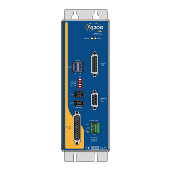
All manuals and user guides at all-guides.com Ndrive QL Hardware Manual Revision: 1.03.00 ENB/FLT SYNC AUX I/O J108 J103 DEVICE NUMBER J104 ANALOG J107 J105 FIREWIRE POWER INPUT STAGE J106 TB101 100-240V~ 50/60Hz 2A MAX DANGER! High Voltage... - Page 2 This manual contains proprietary information and may not be reproduced, disclosed, or used in whole or in part without the express written permission of Aerotech, Inc. Product names mentioned herein are used for identification purposes only and may be trademarks of their respective companies.
-
Page 3: Table Of Contents
All manuals and user guides at all-guides.com Ndrive QL Hardware Manual Table of Contents Table of Contents Ndrive QL Hardware Manual Table of Contents List of Figures List of Tables EU Declaration of Conformity Agency Approvals Safety Procedures and Warnings... -
Page 4: List Of Figures
All manuals and user guides at all-guides.com Table of Contents Ndrive QL Hardware Manual List of Figures Figure 1-1: Functional Diagram Figure 1-2: Dimensions Figure 2-1: Power Input Connections Figure 2-2: Connection to Third Party Stage Figure 2-3: PSO Interface Figure 2-4:... -
Page 5: List Of Tables
All manuals and user guides at all-guides.com Ndrive QL Hardware Manual Table of Contents List of Tables Table 1-1: Configuration and Options Table 1-2: Electrical Specifications Table 1-3: Physical Specifications Table 2-1: Power Supply Wiring (TB101) Table 2-2: I/O and Signal Wiring Specifications... - Page 6 All manuals and user guides at all-guides.com Table of Contents Ndrive QL Hardware Manual This page intentionally left blank. www.aerotech.com...
-
Page 7: Eu Declaration Of Conformity
All manuals and user guides at all-guides.com Ndrive QL Hardware Manual Declaration of Conformity EU Declaration of Conformity Manufacturer Aerotech, Inc. Address 101 Zeta Drive Pittsburgh, PA 15238-2811 Product Ndrive QL Model/Types This is to certify that the aforementioned product is in accordance with the applicable requirements of the... -
Page 8: Agency Approvals
All manuals and user guides at all-guides.com Declaration of Conformity Ndrive QL Hardware Manual Agency Approvals Aerotech, Inc. Model Ndrive QL Drives have been tested and found to be in accordance to the following listed Agency Approvals: Approval / Certification: CUS NRTL Approving Agency: TUV SUD America Inc. -
Page 9: Safety Procedures And Warnings
All manuals and user guides at all-guides.com Ndrive QL Hardware Manual Declaration of Conformity Safety Procedures and Warnings The following statements apply wherever the Warning or Danger symbol appears within this manual. Failure to observe these precautions could result in serious injury to those individuals performing the procedures and/or damage to the equipment. - Page 10 All manuals and user guides at all-guides.com Declaration of Conformity Ndrive QL Hardware Manual This page intentionally left blank. www.aerotech.com...
-
Page 11: Quick Installation Guide
All manuals and user guides at all-guides.com Ndrive QL Hardware Manual Quick Installation Guide Quick Installation Guide This chapter describes the order in which connections and settings should typically be made to the Ndrive QL. If a custom interconnection drawing was created for your system (look for a line item on your Sales Order under the heading “Integration”), that drawing can be found on your Software or Documentation DVD. - Page 12 All manuals and user guides at all-guides.com Quick Installation Guide Ndrive QL Hardware Manual This page intentionally left blank. www.aerotech.com...
-
Page 13: Chapter 1: Introduction
Introduction Chapter 1: Introduction The Ndrive QL is a panel-mount nanopositioning piezo drive that connects to any A3200 controller network enabling a high rate of coordinated motion between piezo stages and servo axes. QL drives feature a dual-core 456 MHz, double-precision, floating-point DSP that provides extreme processing power over a wide variety of applications including point-to-point motion, linear and circular interpolation, multi-axis error correction, and auto-focusing. -
Page 14: Table 1-1: Configuration And Options
All manuals and user guides at all-guides.com Introduction Ndrive QL Hardware Manual Table 1-1: Configuration and Options Ndrive QL Ndrive QL250-C Cost-effective, discrete panel-mount piezo drive with capacitive sensor feedback, 250 mA peak current, 50 mA continuous current, -30 to +150 V output. -
Page 15: Figure 1-1: Functional Diagram
All manuals and user guides at all-guides.com Ndrive QL Hardware Manual Introduction The following block diagram shows a connection summary (refer to Chapter 2 and Chapter 3 for more detailed connection information). SIN, COS, MRK PSO Output 4 Opto Outputs... -
Page 16: Electrical Specifications
All manuals and user guides at all-guides.com Introduction Ndrive QL Hardware Manual 1.1. Electrical Specifications The electrical specifications for the Ndrive QL are listed below. Table 1-2: Electrical Specifications Description Ndrive QL250-C Ndrive QL500-C Input Voltage 100-240 VAC (auto-ranging) 100-240 VAC (auto-ranging) -
Page 17: Mechanical Design
All manuals and user guides at all-guides.com Ndrive QL Hardware Manual Introduction 1.2. Mechanical Design The following figure shows the Ndrive QL package dimension as well as the typical mounting orientation. Ø4.8 [Ø0.19] Ø10.3 [Ø0.41] 20.8 [0.82] 31.8 [1.25] ENB/FLT... -
Page 18: Environmental Specifications
All manuals and user guides at all-guides.com Introduction Ndrive QL Hardware Manual 1.3. Environmental Specifications The environmental specifications for the Ndrive QL are listed below. Ambient Temperature Operating: 0° to 50°C (32° to 122° F) Storage: -30° to 85°C (-22° to 185° F) Humidity Maximum relative humidity is 80% for temperatures up to 31°C. -
Page 19: Chapter 2: Installation And Configuration
Installation and Configuration Chapter 2: Installation and Configuration This section describes the minimum hardware installation and configuration requirements for the Ndrive QL. This installation will provide information on AC power connections and motor wiring. D A N G E R : To minimize the possibility of bodily injury or death, disconnect all electrical power prior to performing any maintenance or making adjustments to the equipment. -
Page 20: Electrical Installation
All manuals and user guides at all-guides.com Installation and Configuration Ndrive QL Hardware Manual 2.2. Electrical Installation The Ndrive QL has one AC input power connector. For a complete list of electrical specifications, refer to Section 1.1. Electrical Specifications. 2.2.1. Power Input (TB101) AC input power to the QL is applied to the Input Power (TB101) connector. -
Page 21: I/O And Signal Wiring Requirements
All manuals and user guides at all-guides.com Ndrive QL Hardware Manual Installation and Configuration 2.2.2. I/O and Signal Wiring Requirements The I/O, communication, and encoder feedback connections are typically very low power connections. In some applications, especially when there are significant wire distances, a larger wire size may be required to reduce the voltage drop that occurs along the wire. -
Page 22: Communication Channel Settings
Ndrive QL Hardware Manual 2.2.3. Communication Channel Settings Use the Device Number switches of S1 to assign a communication channel number to the Ndrive QL. If you are using multiple drives, each drive must be assigned a unique communication channel. Multiple drives are typically configured using sequential communication channels. -
Page 23: Stage Power And Feedback Connections (J106)
2. To avoid the risk of electric shock, do not touch the piezo stage while it is energized. The capacitance sensor interface is designed to work with Aerotech stages and cannot be used with third party sensors. The position feedback input signal (Pin 22) has a range of -10 to 10 VDC and can be connected to a third-party sensor with DC output. -
Page 24: Figure 2-2: Connection To Third Party Stage
All manuals and user guides at all-guides.com Installation and Configuration Ndrive QL Hardware Manual THIRD PARTY STAGE POSITION FEEDBACK (OPTIONAL) SIGNAL COMMON PIEZO ACTUATOR HIGH VOLTAGE OUTPUT (+) PIEZO PIEZO ACTUATOR RETURN (-) FRAME GROUND Figure 2-2: Connection to Third Party Stage Chapter 2 www.aerotech.com... -
Page 25: Auxiliary I/O Connector (J108)
Opto-Isolated Input 2 Opto-Isolated Input 3 1. For PSO, see Section 2.4.1. Mating Connector Aerotech P/N Third Party P/N Connector ECK01259 Kycon K86-AA-26P Backshell ECK01022 Amphenol 17-1725-2 NOTE: These items are provided as a set under the Aerotech P/N: MCK-26HDD. www.aerotech.com Chapter 2... -
Page 26: Position Synchronized Output (Pso)
All manuals and user guides at all-guides.com Installation and Configuration Ndrive QL Hardware Manual 2.4.1. Position Synchronized Output (PSO) The PSO can be programmed to generate an output synchronized to the feedback position and is typically used to fire a laser or sequence an external device. Trigger signals may be derived from a feedback channel or a software trigger. -
Page 27: Figure 2-3: Pso Interface
All manuals and user guides at all-guides.com Ndrive QL Hardware Manual Installation and Configuration Single Ended +5 VDC J108 Active Low Output Aux. Marker Active High Output (±8 mA max) Differential +5 VDC 120 - 180 Ω (typical) J108 Active Low Aux. -
Page 28: Opto-Isolated Outputs
All manuals and user guides at all-guides.com Installation and Configuration Ndrive QL Hardware Manual 2.4.2. Opto-Isolated Outputs 0-3 The digital outputs are optically-isolated and may be connected in sourcing or sinking configurations. The digital outputs are designed to connect to other ground referenced circuits and are not intended to provide high-voltage isolation. -
Page 29: Figure 2-4: Outputs Connected In Current Sourcing Mode (J108)
All manuals and user guides at all-guides.com Ndrive QL Hardware Manual Installation and Configuration J108 OPTOCOM J108-15 OPTOOUT0 J108-7 LOAD OPTOOUT1 J108-8 LOAD OPTOOUT2 J108-9 5-24 VDC LOAD OPTOOUT3 J108-16 OUTPUT SWITCHES LOAD DIODE REQUIRED ON EACH OUTPUT THAT DRIVES AN INDUCTIVE DEVICE (COIL), SUCH AS A RELAY. -
Page 30: Opto-Isolated Inputs
All manuals and user guides at all-guides.com Installation and Configuration Ndrive QL Hardware Manual 2.4.3. Opto-Isolated Inputs 0-3 The digital inputs are opto-isolated and may be connected to current sourcing or current sinking devices, as shown in Figure 2-6 Figure 2-7. -
Page 31: Figure 2-6: Inputs Connected In Current Sourcing Mode (J108)
All manuals and user guides at all-guides.com Ndrive QL Hardware Manual Installation and Configuration J108 INPUT SWITCHES (Current Sourcing) OPTOIN0 J108-17 OPTOIN1 J108-18 OPTOIN2 J108-25 5-24VDC OPTOIN3 J108-26 OPTOINCOM J108-24 Figure 2-6: Inputs Connected in Current Sourcing Mode (J108) J108... -
Page 32: High-Speed User Inputs
Installation and Configuration Ndrive QL Hardware Manual 2.4.4. High-Speed User Inputs 4-5 The Ndrive QL has two high-speed opto-isolated inputs. These can be used as general purpose inputs or as high-speed position capture inputs. Table 2-12: High Speed Digital Input Connector Pin Assignment (J108) -
Page 33: Analog Output
All manuals and user guides at all-guides.com Ndrive QL Hardware Manual Installation and Configuration 2.4.5. Analog Output 0 Table 2-14: Analog Output Specifications (J108) Specification Value Output Voltage -10 V to +10 V Output Current 5 mA Resolution (bits) 16 bits Resolution (volts) 305 µV... -
Page 34: Differential Analog Input
All manuals and user guides at all-guides.com Installation and Configuration Ndrive QL Hardware Manual 2.4.6. Differential Analog Input 0 To interface to a single-ended (non-differential) voltage source, connect the signal common of the source to the negative input and the analog source signal to the positive input. -
Page 35: Analog I/O Connector (J107)
All manuals and user guides at all-guides.com Ndrive QL Hardware Manual Installation and Configuration 2.5. Analog I/O Connector (J107) The Analog I/O connector provides a piezo voltage monitor signal and an external voltage command input. The piezo voltage monitor signal is a scaled copy of the actual piezo actuator's high voltage signal. The external voltage command input allows the user to directly command the high-voltage amplifier. -
Page 36: Voltage Monitor Output
All manuals and user guides at all-guides.com Installation and Configuration Ndrive QL Hardware Manual 2.5.1. Voltage Monitor Output The Voltage Monitor output provides a scaled copy of the piezo actuator's high-voltage signal. The high- voltage signal is scaled by 1/15 and buffered before being sent to the Voltage Monitor output pin. -
Page 37: External Voltage Command
Installation and Configuration 2.5.2. External Voltage Command The External Voltage Command input allows the user to directly command the Ndrive QL's high voltage amplifier. This mode must be enabled using the controller software and is not active by default. Table 2-22:... -
Page 38: Communication
Ndrive QL Hardware Manual 2.6. Communication 2.6.1. FireWire Interface The FireWire bus is the high-speed communications connection to the Ndrive QL operating at 400 megabits per second. All command and configuration information is sent via the FireWire port. J104 J105... -
Page 39: Table 2-27: Firewire Cables (Copper And Glass Fiber)
All manuals and user guides at all-guides.com Ndrive QL Hardware Manual Installation and Configuration Table 2-27: FireWire Cables (copper and glass fiber) Part Number Description NCONNECT-60 6 m (20 ft) long, 6 pin to 6 pin NCONNECT-45 4.5 m (15 ft) long, 6 pin to 6 pin... -
Page 40: Sync Interface
All manuals and user guides at all-guides.com Installation and Configuration Ndrive QL Hardware Manual 2.6.2. SYNC Interface The Sync connection contains a proprietary bus which is currently reserved for future expansion. SYNC J103 ENB/FLT SYNC AUX I/O J108 J103 DEVICE... -
Page 41: Pc Configuration And Operation Information
All manuals and user guides at all-guides.com Ndrive QL Hardware Manual Installation and Configuration 2.7. PC Configuration and Operation Information For additional information about PC configuration, hardware requirements, programming, utilities, and system operation refer to the Help file. www.aerotech.com Chapter 2... - Page 42 All manuals and user guides at all-guides.com Installation and Configuration Ndrive QL Hardware Manual This page intentionally left blank. Chapter 2 www.aerotech.com...
-
Page 43: Chapter 3: Maintenance
D A N G E R : For your own safety and for the safety of the equipment, do not remove the cover of the Ndrive QL or attempt to access its internal components. There is no reason to remove the cover or access the internal components. The QL does not have any user- configurable switches or jumpers. -
Page 44: Preventative Maintenance
Cleaning The Ndrive QL chassis can be wiped with a clean, dry, soft cloth. The cloth may be slightly moistened if required with water or isopropyl alcohol to aid in cleaning if necessary. In this case, be careful not to allow moisture to enter the Ndrive QL or onto exposed connectors / components. -
Page 45: Appendix A: Warranty And Field Service
Aerotech makes no warranty that its products are fit for the use or purpose to which they may be put by the buyer, whether or not such use or purpose has been disclosed to Aerotech in specifications or drawings previously or subsequently provided, or whether or not Aerotech’s... - Page 46 Aerotech's approval. On-site Warranty Repair If an Aerotech product cannot be made functional by telephone assistance or by sending and having the customer install replacement parts, and cannot be returned to the Aerotech service center for repair, and if Aerotech determines the problem could be warranty-related, then the following policy applies:...
-
Page 47: Appendix B: Revision History
All manuals and user guides at all-guides.com Ndrive QL Hardware Manual Revision History Appendix B: Revision History Revision Description 1.03.00 Updated the connector pinout: Section 2.5. Analog I/O Connector (J107) 1.02.00 Updated the connector pinout: Section 2.5. Analog I/O Connector (J107) The following sections have been updated:... - Page 48 All manuals and user guides at all-guides.com Revision History Ndrive QL Hardware Manual This page intentionally left blank. Appendix B www.aerotech.com...
-
Page 49: Index
All manuals and user guides at all-guides.com Ndrive QL Hardware Manual Index Index inspect all cables and connections Inspect cooling vents 2014/35/EU Inspection Installation and Configuration Altitude Ambient Temperature Mechanical Design Check chassis for loose or damaged parts / Peak Inrush Current... - Page 50 All manuals and user guides at all-guides.com Index Ndrive QL Hardware Manual This page intentionally left blank. Index www.aerotech.com...
Need help?
Do you have a question about the Ndrive QL and is the answer not in the manual?
Questions and answers