
Related Manuals for Aerotech ANT95LZS Series


Summary of Contents for Aerotech ANT95LZS Series
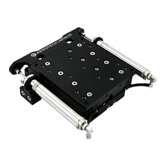
- Page 1 ANT95LZS Series Single-Axis Z Low-Profile Direct-Drive Nanopositioning Stage HARDWARE MANUAL Revision 2.01...
- Page 2 Global Technical Support Portal for information and support about your Aerotech, Inc. products. The website supplies software, product manuals, Help files, training schedules, and PC-to-PC remote technical support. If necessary, you can complete Product Return (RMA) forms and get information about repairs and spare or replacement parts.
-
Page 3: Table Of Contents
ANT95LZS Hardware Manual Table of Contents Table of Contents ANT95LZS Series Single-Axis Z Low-Profile Direct-Drive Nanopositioning Stage Table of Contents List of Figures List of Tables EU Declaration of Incorporation Safety Procedures and Warnings Installation and Operation Electrical Warnings Motor-Related Warnings... -
Page 4: List Of Figures
Figure 2-4: Load Orientations Figure 2-5: Cantilevered Load Capabilities Figure 3-1: ANT95LZS Motor and Feedback Wiring Figure 3-2: Machine Direction Figure 3-3: Hall Phasing Diagram Figure 3-4: Encoder Phasing Reference Diagram (Standard/Square Wave) Figure 3-5: Encoder Phasing Reference Diagram (Analog/Sine Wave) www.aerotech.com... -
Page 5: List Of Tables
List of Tables Table 1-1: Model Numbers and Ordering Options Table 1-2: Environmental Specifications Table 1-3: ANT95LZS Series Specifications Table 2-1: Stage Mounting Surface Flatness Requirement Table 2-2: Stage to Mounting Surface Hardware Table 2-3: Payload to Stage Surface Hardware... - Page 6 List of Tables ANT95LZS Hardware Manual This page intentionally left blank. www.aerotech.com...
-
Page 7: Eu Declaration Of Incorporation
ANT95LZS Hardware Manual EU Declaration of Incorporation EU Declaration of Incorporation Manufacturer Aerotech, Inc. 101 Zeta Drive Pittsburgh, PA 15238-2811 herewith declares that the product: ANT95LZS Linear Stage is intended to be incorporated into machinery to constitute machinery covered by the Directive 2006/42/EC as amended;... -
Page 8: Safety Procedures And Warnings
To find the newest information about this product, refer to www.aerotech.com. If you do not understand the information in this manual, contact Aerotech Global Technical Support. IMPORTANT: This product has been designed for light industrial manufacturing or laboratory environments. -
Page 9: Installation And Operation
WARNING: Trip Hazard! Route, house, and secure all cables, duct work, air, or water lines. Failure to do so could introduce trip hazards around the system that could result in physical injury or could damage the equipment. www.aerotech.com... -
Page 10: Electrical Warnings
It is the responsibility of the End User/System Integrator to make sure that stages are properly connected and grounded per Engineering Standards and applicable safety requirements. It is the responsibility of the End User/System Integrator to configure the system drive or controller within the Aerotech motor/stage electrical and mechanical specifications. www.aerotech.com... -
Page 11: Motor-Related Warnings
ANT95LZS Hardware Manual Motor-Related Warnings Motor-Related Warnings Aerotech motors are capable of producing high forces and velocities. Obey all warnings and all applicable codes and standards when you use or operate a stage or system that incorporates Aerotech motors. DANGER: Hot Surface Hazard! The stage/motor frame temperature could exceed 70°C in some applications. -
Page 12: Pinch Points
(during normal operation, for example). when the system is moved manually (during the installation process or when you do maintenance, for example). Motors are capable of very high speeds and acceleration rates. Figure 1: Typical Pinch Point Locations www.aerotech.com... -
Page 13: Magnetic Hazards
Loose items such as metallic tools, watches, or keys could get drawn into and dam- age the magnet track assembly. IMPORTANT: Use non-magnetic tools when you install or do service to the stage. Figure 2: Exposed Magnet Locations www.aerotech.com... -
Page 14: Handling And Storage
Before you operate the stage, let it stabilize at room temperature for at least 12 hours. This will ensure that all of the alignments, preloads, and tolerances are the same as they were when they were tested at Aerotech. www.aerotech.com... - Page 15 Store the stage in the original shipping container. If the original packaging included ESD protective packaging, make sure to store the stage in it. The storage location must be dry, free of dust, free of vibrations, and flat. Refer to Section 1.1. Environmental Specifications www.aerotech.com...
- Page 16 Handling and Storage ANT95LZS Hardware Manual This page intentionally left blank. www.aerotech.com...
-
Page 17: Chapter 1: Overview
Integration (Required) Test as system: Testing, integration, and documentation of a group of -TAS components as a complete system that will be used together. Test as components: Testing and integration of individual items as discrete -TAC components that ship together. www.aerotech.com... -
Page 18: Environmental Specifications
Indoor use only 1.2. Accuracy and Temperature Effects Aerotech products are designed for and built in a 20°C (68°F) environment. Extreme temperature changes could cause a decrease in performance or permanent damage to the stage. At a minimum, the environmental temperature must be controlled to within 0.25ºC per 24 hours to ensure the stage specifications are repeatable over an extended period of time. -
Page 19: Basic Specifications
6. To ensure the achievement and repeatability of specifications over an extended period of time, environmental temperature must be controlled to within 0.25°C per 24 hours. Consult the Aerotech factory for more information. 7. The air supply for the pneumatic counterbalance must be clean, dry to 0°F dewpoint, and filtered to 0.25 µm or better. -
Page 20: Air Requirements
If compressed air is used, it must be filtered to 0.25 microns, dry to 0º F dew point, and oil free. The maximum allowable input pressure specification is 0.6 MPa (87 psi). The low friction air cylinder consumes air as described in Figure 1-1. Figure 1-1: Counterbalance Air Flow vs. Counterbalance Pressure Figure 1-2: Air Inlet Location www.aerotech.com... -
Page 21: Chapter 2: Installation
IMPORTANT: The stage installation must be in accordance with the instructions provided by this manual and any accompanying documentation. Failure to follow these instructions could result in injury or damage to the equipment. 2.1. Dimensions Figure 2-1: ANT95LZS Dimensions www.aerotech.com... -
Page 22: Securing The Stage To The Mounting Surface
5. Two Person Step: Lift the carriage by hand, and hold it up to expose the bottom mounting holes. Insert the remaining mounting screws. Align the stage per your application, and then tighten the mounting screws. Refer to Table 2-2 for screw torque specifications. www.aerotech.com... -
Page 23: Figure 2-2: Mounting Hole Pattern
Stage to Mounting Surface Hardware Typical Screw Torque Mounting Hardware M4 SHCS (stage mounting) 2.0 N·m [18 lb·in] M5X0.8 (alternate mounting) 4.1 N·m [36 lb·in] M6 or (1/4") SHCS ([-MP] option) 7.0 N·m [61 lb·in] Figure 2-2: Mounting Hole Pattern www.aerotech.com... -
Page 24: Setting Up The Pneumatic Counterbalance
) / 1x10 {MPa} where Pc = Required counterbalance pressure in MPa (maximum 0.6 MPa allowed) mp = mass of external payload in kg. This relationship is shown graphically in Figure 2-3. Figure 2-3: Counterbalance Pressure vs. External Payload www.aerotech.com... - Page 25 2. Gently push the carriage down to the bottom of travel until the mechanical shock engages. 3. Turn off the counterbalance pressure. Once the counterbalance pressure has completely bled out, release the hand pressure on the carriage. To change the payload on the stage (add or remove mass), refer to Section 2.3. www.aerotech.com...
-
Page 26: Attaching The Payload To The Stage
If you start the ANT95LZS without a payload, the servo gains provided by Aerotech with the shipment may not be appropriate and servo instability can occur. Refer to the controller help file for tuning assistance. -
Page 27: Figure 2-4: Load Orientations
This will allow the tabletop to fall a small amount. 8. Adjust the air supply pressure until the tabletop reaches equilibrium. 9. Completely remove the shipping clamp, and verify the stage is at equilibrium. Make adjustments as necessary. 10. Reconnect the electrical power. Figure 2-4: Load Orientations www.aerotech.com... -
Page 28: Figure 2-5: Cantilevered Load Capabilities
2.3. Attaching the Payload to the Stage ANT95LZS Hardware Manual Figure 2-5: Cantilevered Load Capabilities www.aerotech.com... -
Page 29: Chapter 3: Electrical Installation
Aerotech motion control systems are adjusted at the factory for optimum performance. When the ANT95LZS is part of a complete Aerotech motion control system, setup should only require that you connect the stage to the appropriate drive chassis with the cables provided. Labels on the system components should indicate the appropriate connections. -
Page 30: Motor And Feedback Connectors
Stages equipped with standard motors and encoders come from the factory completely wired and assembled. IMPORTANT: Refer to the other documentation accompanying your Aerotech equipment. Call your Aerotech representative if there are any questions on system configuration. IMPORTANT: If using standard Aerotech motors and cables, motor and encoder connection adjustments are not required. -
Page 31: Table 3-1: 25-Pin Motor And Feedback Connector Pinout
Hall Effect Sensor (Phase B) Frame Ground and Shield Connection Motor Phase A Motor Phase B Motor Phase C Table 3-2: 25-Pin Mating Connector Part Numbers Mating Connector Aerotech P/N Third Party P/N 25-Socket D-Connector ECK00300 FCI DB25S064TLF Backshell ECK00656 Amphenol 17E-1726-2... -
Page 32: Motor And Feedback Wiring
3.2. Motor and Feedback Wiring ANT95LZS Hardware Manual 3.2. Motor and Feedback Wiring Shielded cables are required for the motor and feedback connections. Figure 3-1: ANT95LZS Motor and Feedback Wiring www.aerotech.com... -
Page 33: Motor And Feedback Specifications
Requires external pull-up to +5 V (10 kΩ recommended) Note: If the ANT95LZS is driven beyond the electrical limit, it will encounter a mechanical stop. Impacting the mechanical stop could cause damage to the stage even at low speeds. www.aerotech.com... -
Page 34: Table 3-7: Ant95Lzs Motor Specifications
5. All performance and electrical specifications ±10%. 6. Maximum winding temperature is 125°C. 7. Ambient operating temperature range 0 °C - 25 °C; consult Aerotech for performance in elevated ambient temperatures. 8. All Aerotech amplifiers are rated Apk; use force constant in N·m/Apk when sizing. -
Page 35: Limits, Marker, And Machine Direction
3.4. Limits, Marker, and Machine Direction 3.4. Limits, Marker, and Machine Direction Aerotech stages are configured to have positive and negative "machine" directions. The machine direction defines the phasing of the feedback and motor signals and is dictated by the stage wiring... -
Page 36: Motor And Feedback Phasing
3.5. Motor and Feedback Phasing ANT95LZS Hardware Manual 3.5. Motor and Feedback Phasing Motor phase voltage is measured relative to the virtual wye common point. Figure 3-3: Hall Phasing Diagram www.aerotech.com... -
Page 37: Figure 3-4: Encoder Phasing Reference Diagram (Standard/Square Wave)
ANT95LZS Hardware Manual 3.5. Motor and Feedback Phasing Figure 3-4: Encoder Phasing Reference Diagram (Standard/Square Wave) Figure 3-5: Encoder Phasing Reference Diagram (Analog/Sine Wave) www.aerotech.com... - Page 38 3.5. Motor and Feedback Phasing ANT95LZS Hardware Manual This page intentionally left blank. www.aerotech.com...
-
Page 39: Chapter 4: Maintenance
Visually inspect the stage and cables. Re-tighten loose connectors. Replace or repair damaged cables. Clean the ANT95LZS and any components and cables as needed. Repair any damage before operating the ANT95LZS. Inspect and perform an operational check on all safeguards and protective devices. www.aerotech.com... -
Page 40: Cleaning And Lubrication
5. We recommend that you do not disassemble the stage beyond the instructions given in this manual. Proper assembly and calibration can only be done at the factory. Contact Aerotech for more information. Cleaning Use isopropyl alcohol on a lint-free cloth to clean any external metal surface of the ANT95LZS. - Page 41 4. Apply a thin, continuous film of lubricant to the exposed v-channels of the cross rollers on both ends of the stage. Aerotech recommends that you use a good quality, natural bristle artist's brush for the applicator. Do not use any applicator that could scratch or otherwise damage the v-channels.
-
Page 42: Troubleshooting
Chapter 3: Electrical Installation and Controller documentation). Stage moves uncontrollably Motor Connections (refer to Chapter 3: Electrical Installation and the Controller documentation). Gains misadjusted (refer to the Controller documentation). Stage oscillates or squeals Encoder signals (refer to the Controller documentation). www.aerotech.com... -
Page 43: Appendix A: Warranty And Field Service
All Other Repairs - After Aerotech's evaluation, the buyer shall be notified of the repair cost. At such time the buyer must issue a valid purchase order to cover the cost of the repair and freight, or authorize the product(s) to be shipped back as is, at the buyer's expense. - Page 44 Aerotech's approval. On-site Warranty Repair If an Aerotech product cannot be made functional by telephone assistance or by sending and having the customer install replacement parts, and cannot be returned to the Aerotech service center for...
-
Page 45: Appendix B: Revision History
ANT95LZS Hardware Manual Appendix B: Revision History Appendix B: Revision History Revision Description 2.01 Safety information updated. 2.00 New manual www.aerotech.com... - Page 46 Appendix B: Revision History ANT95LZS Hardware Manual This page intentionally left blank. www.aerotech.com...
-
Page 47: Index
Electrical Warnings Hall-Effect Sensors EN 60204-1 2010 Limit Switch EN ISO 12100 2010 Thermistor Specifications Encoder Specifications stabilizing stage EU 2015/863 stage distortion stabilizing Hall-Effect Sensors Specifications Storage Handling Symptom Humidity Table of Contents Inspection Schedule Temperature Effects isopropyl alcohol www.aerotech.com... - Page 48 Index ANT95LZS Hardware Manual Thermistor Specifications Troubleshooting Vibration Warnings Warranty and Field Service www.aerotech.com...
Need help?
Do you have a question about the ANT95LZS Series and is the answer not in the manual?
Questions and answers