Table of Contents
Advertisement
Quick Links
Advertisement
Table of Contents

Related Manuals for Aerotech Automation1 XC4e


Summary of Contents for Aerotech Automation1 XC4e
-
Page 1: Automation1 Xc4E High-Performance Pwm Digital Drive
Automation1 XC4e High-Performance PWM Digital Drive HARDWARE MANUAL Revision 2.01... - Page 2 This manual contains proprietary information and may not be reproduced, disclosed, or used in whole or in part without the express written permission of Aerotech, Inc. Product names mentioned herein are used for identification purposes only and may be trademarks of their respective companies.
-
Page 3: Table Of Contents
XC4e Hardware Manual Table of Contents Table of Contents Automation1 XC4e High-Performance PWM Digital Drive Table of Contents List of Figures List of Tables EU Declaration of Conformity Agency Approvals Safety Procedures and Warnings Installation Overview Chapter 1: Introduction 1.1. Electrical Specifications 1.1.1. - Page 4 3.4. Analog Inputs [-EB1] 3.5. Position Synchronized Output Interface [-EB1] Chapter 4: Cables and Accessories 4.1. Joystick Interface 4.2. Handwheel Interface Chapter 5: Maintenance 5.1. Preventative Maintenance 5.2. Fuse Specifications Appendix A: Warranty and Field Service Appendix B: Revision History Index www.aerotech.com...
-
Page 5: List Of Figures
Digital Outputs Connected in Current Sourcing Mode Figure 2-41: Digital Outputs Connected in Current Sinking Mode Figure 2-42: Digital Inputs Schematic (Aux I/O Connector) Figure 2-43: Digital Inputs Connected to Current Sinking Devices Figure 2-44: Digital Inputs Connected to Current Sourcing Devices www.aerotech.com... - Page 6 Two Axis Joystick Interface (to the Aux I/O of two drives) Figure 4-2: Two Axis Joystick Interface (to the I/O board) Figure 4-3: Handwheel Interconnection to Aux I/O Connector Figure 4-4: Handwheel Interconnection to the Aux I/O through a BBA32 Module www.aerotech.com...
-
Page 7: List Of Tables
Motor Power Output Connector Pinout Table 2-8: Mating Connector Part Numbers for the Motor Power Output Connector Table 2-9: Wire Colors for Aerotech-Supplied Brushless Motor Cables Table 2-10: Hall Signal Diagnostics Table 2-11: Wire Colors for Aerotech-Supplied DC Brush Motor Cables... - Page 8 Table 3-18: PSO Interface Connector Pinout [-EB1] Table 3-19: Mating Connector Part Numbers for the PSO Interface Connector [-EB1] Table 4-1: Standard Interconnection Cables Table 5-1: LED Description Table 5-2: Troubleshooting Table 5-3: Preventative Maintenance Table 5-4: Control Board Fuse Specifications www.aerotech.com...
-
Page 9: Eu Declaration Of Conformity
XC4e Hardware Manual EU Declaration of Conformity EU Declaration of Conformity Manufacturer Aerotech, Inc. Address 101 Zeta Drive Pittsburgh, PA 15238-2811 Product XC4e Model/Types This is to certify that the aforementioned product is in accordance with the applicable requirements of... - Page 10 EU Declaration of Conformity XC4e Hardware Manual This page intentionally left blank. www.aerotech.com...
-
Page 11: Agency Approvals
Certificate #: Z10 068995 0030 Rev. 00 Standards: IEC 61508-1:2010 (up to SIL 3) Visit https://www.tuev-sued.de/product-testing/certificates to view Aerotech's TÜV SÜD certificates. Type the certificate number listed above in the search bar or type "Aerotech" for a list of all Aerotech certificates. www.aerotech.com... - Page 12 Agency Approvals XC4e Hardware Manual This page intentionally left blank. www.aerotech.com...
-
Page 13: Safety Procedures And Warnings
To find the newest information about this product, refer to www.aerotech.com. If you do not understand the information in this manual, contact Aerotech Global Technical Support. IMPORTANT: This product has been designed for light industrial manufacturing or laboratory environments. - Page 14 Safety Procedures and Warnings XC4e Hardware Manual This page intentionally left blank. www.aerotech.com...
-
Page 15: Installation Overview
(if you purchased the I/O option). Chapter 3 Connect the Safe Torque Off (STO). Section 2.4. Connect the power supply to the Control Supply connector. Section 2.1.1. Connect the motor power to the Motor Supply connector. Section 2.1.2. Figure 1: Installation Connection Overview www.aerotech.com... - Page 16 Installation Overview XC4e Hardware Manual This page intentionally left blank. www.aerotech.com...
-
Page 17: Chapter 1: Introduction
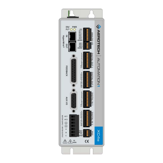
The XC4e is offered with optional encoder interpolation features (-MX2/-MX3), an auxiliary encoder input for dual loop control, dedicated analog and digital I/O (expandable with the -EB1 option), and separate power connections for motor and control supply voltages. Figure 1-1: XC4e Digital Drive www.aerotech.com... -
Page 18: Table 1-1: Features And Options
3 or more axes (includes One-Axis PSO). External Shunt Section 2.8. -SX0 No connector for the External Shunt -SX1 Connection provided for an external shunt resistor network Version -DEFAULT Firmware Matches Software Line -LEGACY Legacy Firmware Version X.XX.XXX www.aerotech.com... -
Page 19: Figure 1-2: Functional Diagram
XC4e Hardware Manual Chapter 1: Introduction The block diagram that follows shows a summary of the connector signals. Figure 1-2: Functional Diagram www.aerotech.com... -
Page 20: Electrical Specifications
Optical and transformer isolation between control and Isolation power stages. (1) AC input voltage and load dependent. (2) Dependent on total output power: efficiency increases with increasing output power. (3) Current is measured as the peak amplitude in any motor phase www.aerotech.com... -
Page 21: System Power Requirements
Power Loss = 3 * I(rms)^2 * R(line-line)/2 Power Input = (Power Output + Power Loss) / EfficiencyFactor DC Brush Motor Power Output [W] = Torque [N·m] * Angular velocity[rad/sec] Power Loss = I(rms)^2 * R Power Input = (Pout + Ploss) / EfficiencyFactor www.aerotech.com... -
Page 22: Mechanical Specifications
IP54 Compliant Weight ~2.36 kg Mounting Hardware M4 [#8] screws (four locations, not included) Mounting Orientation Vertical (typical) Section 1.2.2. Dimensions Dimensions Refer to Airflow ~25 mm Minimum Clearance Connectors ~100 mm Operating Temperature Refer to Section 1.3. Environmental Specifications www.aerotech.com... -
Page 23: Dimensions
XC4e Hardware Manual 1.2.2. Dimensions 1.2.2. Dimensions Figure 1-3: Dimensions www.aerotech.com... -
Page 24: Figure 1-4: Dimensions [-Eb1]
1.2.2. Dimensions XC4e Hardware Manual Figure 1-4: Dimensions [-EB1] www.aerotech.com... -
Page 25: Environmental Specifications
0 m to 2,000 m (0 ft to 6,562 ft) above sea level. Operating Altitude If you must operate this product above 2,000 m or below sea level, contact Aerotech, Inc. Pollution Degree 2 Pollution Typically only nonconductive pollution occurs. -
Page 26: Drive And Software Compatibility
Last Software Version column, drives that show a specific version number are not supported after that version. Table 1-5: Drive and Software Compatibility Drive Type Software First Software Version Last Software Version Automation1 Current Automation1 XC4e A3200 6.04 Current www.aerotech.com... -
Page 27: Chapter 2: Installation And Configuration
Additional information about the system is provided on the Serial and Power labels that are placed on the XC4e chassis. The system serial number label contains important information such as the: Customer order number (please provide this number when requesting product support) Drawing number System part number www.aerotech.com... -
Page 28: Input Power Connections
The Control Supply contains an internal filter but you could be required to add an external filter for CE compliance. Install the external filter as close as possible to the XC4e. Use a Schaffner FN2080 filter, an Aerotech UFM-ST noise filter module, or equivalent device. IMPORTANT: Refer to local electrical safety requirements to correctly size external system wires. -
Page 29: Motor Supply Connector
IMPORTANT: Before you operate the XC4e, install a ground connection for your safety and to prevent damage to the equipment. For CE compliance, Aerotech recommends that you use an AC line filter. Connect the filter as close as possible to the drive. For more information about the AC line filter, refer to Section 2.1.4. -
Page 30: Transformer Options
TV0.3-56 rectified by the drive, it produces an 80 VDC power bus. 1.5 kVA, 2.5 kVA, or 5 kVA isolation transformer; 115/230 VAC input; 28, 43, TV1.5, TV2.5, or TV5 56, 70, 115 VAC output Figure 2-3: Transformer Examples www.aerotech.com... -
Page 31: Figure 2-4: Tv0.3-28-56-St Transformer Control And Motor Power Wiring (40 Vdc Bus)
XC4e Hardware Manual 2.1.3. Transformer Options Figure 2-4: TV0.3-28-56-ST Transformer Control and Motor Power Wiring (40 VDC Bus) www.aerotech.com... -
Page 32: Figure 2-5: Tv0.3-28-56-St Transformer Control And Motor Power Wiring (80 Vdc Bus)
2.1.3. Transformer Options XC4e Hardware Manual Figure 2-5: TV0.3-28-56-ST Transformer Control and Motor Power Wiring (80 VDC Bus) www.aerotech.com... -
Page 33: Figure 2-6: Tv0.3-28-56-St Transformer Control And Motor Power Wiring (160 Vdc Bus)
XC4e Hardware Manual 2.1.3. Transformer Options Figure 2-6: TV0.3-28-56-ST Transformer Control and Motor Power Wiring (160 VDC Bus) www.aerotech.com... -
Page 34: Figure 2-7: Tv0.3-28 Transformer Control And Motor Power Wiring (40 Vdc Bus)
2.1.3. Transformer Options XC4e Hardware Manual Figure 2-7: TV0.3-28 Transformer Control and Motor Power Wiring (40 VDC Bus) www.aerotech.com... -
Page 35: Figure 2-8: Tv0.3-56 Transformer Control And Motor Power Wiring (80 Vdc Bus)
XC4e Hardware Manual 2.1.3. Transformer Options Figure 2-8: TV0.3-56 Transformer Control and Motor Power Wiring (80 VDC Bus) www.aerotech.com... -
Page 36: Figure 2-9: Tm3/Tm5 Transformer Control And Motor Power Wiring
2.1.3. Transformer Options XC4e Hardware Manual Figure 2-9: TM3/TM5 Transformer Control and Motor Power Wiring www.aerotech.com... -
Page 37: Minimizing Noise For Emc/Ce Compliance
Use a line fil- ter, such as Aerotech’s UFM-ST, on the Motor Supply and Control Supply AC inputs. 4. Use the lowest motor voltage required by the application to reduce radiated emission. -
Page 38: Motor Power Output Connector
Stepper Brushless Phase C Motor Lead 1.3 mm (#16 AWG) DC Brush - Stepper Return Table 2-8: Mating Connector Part Numbers for the Motor Power Output Connector Aerotech Third Part Screw Wire Size: Type Torque: Nm [AWG] 7-Pin Terminal Block ECK02387 Phoenix 1756353 0.5 - 0.6... -
Page 39: Brushless Motor Connections
Black #3 Violet & Blue (1) Wire Color Set #1 is the wire set typically used by Aerotech. (2) “&” indicates two wires (Red & Orange); “ / ” indicates a single wire (Green/White). Brushless motors are commutated electronically by the controller. The use of Hall effect devices for commutation is recommended. -
Page 40: Brushless Motor Powered Motor And Feedback Phasing
Observe the state of the encoder and Hall-effect device signals in the Diagnostics section of the Status Utility. Table 2-10: Hall Signal Diagnostics Hall-Signal Status Definition 0 V or logic low 5 V or logic high Figure 2-11: Positive Motor Direction Figure 2-12: Encoder and Hall Signal Diagnostics www.aerotech.com... -
Page 41: Brushless Motor Unpowered Motor And Feedback Phasing
With the designations of the motor and Hall leads of a third party motor determined, the motor can now be connected to an Aerotech system. Connect motor lead A to motor connector A, motor lead B to motor connector B, and motor lead C to motor connector C. Hall leads should also be connected to their respective feedback connector pins (Hall A lead to the Hall A feedback pin, Hall B to Hall B, and Hall C to Hall C). -
Page 42: Dc Brush Motor Connections
Red & Orange Yellow & Blue Black Yellow & Blue (1) Wire Color Set #1 is the typical wire set used by Aerotech. (2) “&” (Red & Orange) indicates two wires; “ / ” (Green/White) indicates a single wire. www.aerotech.com... -
Page 43: Dc Brush Motor Phasing
5. Connect the motor lead from the positive lead of the voltmeter to the ØA motor terminal on the XC4e. Connect the motor lead from the negative lead of the voltmeter to the ØC motor terminal on the XC4e. For Aerotech-supplied systems, the motor, encoder and Hall sensors are correctly configured and connection adjustments are not necessary. www.aerotech.com... -
Page 44: Stepper Motor Connections
Green/Yellow & Shield Green/Yellow & Shield Black Brown Yellow White White & Red (1) Wire Color Set #1 is the typical wire set used by Aerotech. (2) “&” (Red & Orange) indicates two wires; “ / ” (Green/White) indicates a single wire. www.aerotech.com... -
Page 45: Stepper Motor Phasing
After the motor has been phased, if you want to change the direction of positive motion, use the ReverseMotionDirection parameter. Figure 2-18: Positive Motor Direction For Aerotech-supplied systems, the motor, encoder and Hall sensors are correctly configured and connection adjustments are not necessary. www.aerotech.com... -
Page 46: Feedback Connector
Pin # Description In/Out/Bi Connector Reserved Motor Over Temperature Thermistor Input +5V Power Plug and Play Serial Data (for Aerotech stages only) Bidirectional Hall-Effect Sensor B (brushless motors only) Input Encoder Marker Reference Pulse - Input Absolute Encoder Clock -... -
Page 47: Primary Encoder Inputs
Absolute Encoder Data - Bidirectional Encoder Cosine + Input Encoder Cosine - Input +5V Power Encoder Sine + Input Encoder Sine - Input Absolute Encoder Data+ Bidirectional Signal Common Signal Common (1) The maximum combined current output is 500 mA. www.aerotech.com... -
Page 48: Square Wave Encoder
Table 2-17: Square Wave Encoder Specifications Specification Value Encoder Frequency 10 MHz maximum (25 ns minimum edge separation) x4 Quadrature Decoding 40 million counts/sec Figure 2-19: Square Wave Encoder Schematic (Feedback Connector) www.aerotech.com... -
Page 49: Absolute Encoder
You cannot echo an absolute encoder signal. Refer to Figure 2-20 for the serial data stream interface. Refer to the Help file for information on how to set up your EnDat or BiSS absolute encoder parameters. Figure 2-20: Absolute Encoder Schematic (Feedback Connector) www.aerotech.com... -
Page 50: Sine Wave Encoder [-Mx2/-Mx3 Option]
16,384 -MX2/-MX3 Primary Encoder Channel 800 nsec (analog input to quadrature output) Interpolation Latency Input Common Mode 1.5 to 3.5 VDC (1) Measured as SIN(+) - SIN(-) or COS(+) - COS(-) Figure 2-21: Sine Wave Encoder Phasing Reference Diagram www.aerotech.com... -
Page 51: Figure 2-22: Sine Wave Encoder Schematic (Feedback Connector)
XC4e Hardware Manual 2.3.1. Primary Encoder Inputs Figure 2-22: Sine Wave Encoder Schematic (Feedback Connector) www.aerotech.com... -
Page 52: Encoder Phasing
Figure 2-23: Encoder Phasing Reference Diagram (Standard) IMPORTANT: Encoder manufacturers may refer to the encoder signals as A, B, and Z. The proper phase relationship between signals is shown in Figure 2-23. Figure 2-24: Position Feedback in the Diagnostic Display www.aerotech.com... -
Page 53: Hall-Effect Inputs
Hall-Effect Sensor B (brushless motors only) Input Hall-Effect Sensor A (brushless motors only) Input Hall-Effect Sensor C (brushless motors only) Input +5V Power Signal Common Signal Common (1) The maximum combined current output is 500 mA. Figure 2-25: Hall-Effect Inputs Schematic (Feedback Connector) www.aerotech.com... -
Page 54: Thermistor Input
1.385 kΩ. The circuit includes a 12 kΩ internal pull-up resistor which corresponds to a trip voltage of +0.52 V. Table 2-20: Thermistor Input Pin on the Feedback Connector Pin # Description In/Out/Bi Motor Over Temperature Thermistor Input Figure 2-26: Thermistor Input Schematic (Feedback Connector) www.aerotech.com... -
Page 55: Encoder Fault Input
The nominal trip voltage of the encoder fault input is +2.5 V. Table 2-21: Encoder Fault Input Pin on the Feedback Connector Pin # Description In/Out/Bi Encoder Fault Input Input Figure 2-27: Encoder Fault Input Schematic (Feedback Connector) www.aerotech.com... -
Page 56: End Of Travel And Home Limit Inputs
IMPORTANT: Use NPN-type normally-closed limit switches (Active High) to provide fail- safe behavior in the event of an open circuit. www.aerotech.com... -
Page 57: Figure 2-28: End Of Travel And Home Limit Input Connections
XC4e Hardware Manual 2.3.5. End of Travel and Home Limit Inputs Figure 2-28: End of Travel and Home Limit Input Connections Figure 2-29: End of Travel and Home Limit Input Schematic (Feedback Connector) www.aerotech.com... -
Page 58: End Of Travel And Home Limit Phasing
CW and CCW inputs at the Feedback connector or swap the CW and CCW limit functionality in the software using the EndOfTravelLimitSetup parameter. View the logic level of the EOT limit inputs in the Diagnostics display (shown in Figure 2-30). Figure 2-30: End of Travel and Home Limit Input Diagnostic Display www.aerotech.com... -
Page 59: Brake Outputs
Brake Output + Output Table 2-24: Brake Control Specifications Specification Value Maximum Voltage 24 VDC Maximum Current A varistor must be connected across the brake to minimize voltage transients. Figure 2-31: Brake Connected to the 25-Pin Feedback Connector (Typical) www.aerotech.com... -
Page 60: Safe Torque Off Input (Sto)
STO 2 IN STO Channel 2 Positive Input Input Power Supply - Used to defeat STO by connecting to RETURN Table 2-26: Mating Connector Part Numbers for the STO Connector Tightening Aerotech Phoenix Torque Wire Size: Description (Nm) AWG [mm 5-Pin Terminal Block... -
Page 61: Figure 2-32: Typical Configuration
WARNING: The XC4e does not check for short circuits on the external STO wiring. If this is not done by the external safety device, short circuits on the wiring must be excluded. Refer to EN ISO 13849-2. For Category 4 systems, the exclusion of short circuits is mandatory. Figure 2-32: Typical Configuration www.aerotech.com... -
Page 62: Sto Standards
Interval for manual STO test: EN/IEC 61508 Once per year for SIL2/PL d/category 3 Once per three months for SIL3/PL e/category 3 Once per day for SIL3/PL e/category 4 SIL3 EN/IEC 61508 PFH < 3 FIT SFF > 99% www.aerotech.com... -
Page 63: Sto Functional Description
Connect the ESTOP signal directly to a digital input, in addition to the external timer, to allow the XC4e to begin a software-controlled stop as soon as the ESTOP signal becomes active. Use the EmergencyStopFaultInput [A3200: ESTOPFaultInput] parameter to configure a digital input as an ESTOP input. www.aerotech.com... -
Page 64: Sto Startup Validation Testing
(open circuit or 0 V), and that the STO channel is in the safe state. DANGER: The STO circuit does not remove lethal voltage from the motor terminals. AC mains power must be removed before servicing. www.aerotech.com... -
Page 65: Sto Diagnostics
STO inputs before the STO Delay Time, an STO hardware shutdown will not occur but a software stop may, depending on the width of the STO pulse. The controller will ignore STO active pulses shorter in length than the STOPulseFilter parameter setting. www.aerotech.com... -
Page 66: Auxiliary I/O Connector
(2) For PSO, refer to Section 2.5.2. Table 2-34: Mating Connector Part Numbers for the Auxiliary I/O Connector Mating Connector Aerotech P/N Third Party P/N Connector ECK01259 Kycon K86-AA-26P Backshell ECK01022 Amphenol 17-1725-2 NOTE: These items are provided as a set under the Aerotech P/N: MCK-26HDD. www.aerotech.com... -
Page 67: Auxiliary Encoder Inputs
Absolute Encoder Clock + Output Auxiliary Cosine- Bidirectional Absolute Encoder Clock - Output +5 Volt (500 mA max) Auxiliary Marker- / PSO output / TTL Output Bidirectional Auxiliary Marker+ / PSO output Bidirectional Common (2) For PSO, refer to Section 2.5.2. www.aerotech.com... -
Page 68: Square Wave Encoder
Table 2-36: Square Wave Encoder Specifications Specification Value Encoder Frequency 10 MHz maximum (25 ns minimum edge separation) x4 Quadrature Decoding 40 million counts/sec Figure 2-34: Square Wave Encoder Interface (Aux I/O Connector) www.aerotech.com... -
Page 69: Absolute Encoder
You cannot use an absolute encoder with incremental signals on the Auxiliary I/O Connector. Refer to Figure 2-35 for the serial data stream interface. Refer to the Help file for information on how to set up your EnDat or BiSS absolute encoder parameters. Figure 2-35: Absolute Encoder Schematic (Auxiliary I/O Connector) www.aerotech.com... -
Page 70: Sine Wave Encoder [-Mx3 Option]
16,384 -MX2/-MX3 Primary Encoder Channel 800 nsec (analog input to quadrature output) Interpolation Latency Input Common Mode 1.5 to 3.5 VDC (1) Measured as SIN(+) - SIN(-) or COS(+) - COS(-) Figure 2-36: Sine Wave Encoder Phasing Reference Diagram www.aerotech.com... -
Page 71: Figure 2-37: Sine Wave Encoder Schematic (Auxiliary I/O Connector)
XC4e Hardware Manual 2.5. Auxiliary I/O Connector Figure 2-37: Sine Wave Encoder Schematic (Auxiliary I/O Connector) www.aerotech.com... -
Page 72: Position Synchronized Output (Pso)
12.5 MHz Output Latency 15 ns RS-422 15 ns [Fire event to output change] Table 2-39: PSO Pins on the Auxiliary I/O Connector Pin# Description In/Out/Bi Auxiliary Marker- / PSO output / TTL Output Bidirectional Auxiliary Marker+ / PSO output Bidirectional Common www.aerotech.com... -
Page 73: Figure 2-38: Pso Interface
XC4e Hardware Manual 2.5. Auxiliary I/O Connector Figure 2-38: PSO Interface www.aerotech.com... -
Page 74: Digital Outputs
Reset State Output Off (High Impedance State) Table 2-41: Digital Output Pins on the Auxiliary I/O Connector Pin# Description In/Out/Bi Digital Output 0 Output Digital Output 1 Output Digital Output 2 Output Digital Output Common Digital Output 3 Output www.aerotech.com... -
Page 75: Figure 2-39: Digital Output Schematic (Aux I/O Connector)
XC4e Hardware Manual 2.5. Auxiliary I/O Connector Figure 2-39: Digital Output Schematic (Aux I/O Connector) www.aerotech.com... -
Page 76: Figure 2-40: Digital Outputs Connected In Current Sourcing Mode
2.5. Auxiliary I/O Connector XC4e Hardware Manual Figure 2-40: Digital Outputs Connected in Current Sourcing Mode Figure 2-41: Digital Outputs Connected in Current Sinking Mode www.aerotech.com... -
Page 77: Digital Inputs
Digital Input 0 / CCW EOT Input Input Digital Input 1 / CW EOT Input Input Digital Input Common Digital Input 2 / Home Input Input Digital Input 3 Input (1) Software configured option Figure 2-42: Digital Inputs Schematic (Aux I/O Connector) www.aerotech.com... -
Page 78: Figure 2-43: Digital Inputs Connected To Current Sinking Devices
2.5. Auxiliary I/O Connector XC4e Hardware Manual Figure 2-43: Digital Inputs Connected to Current Sinking Devices Figure 2-44: Digital Inputs Connected to Current Sourcing Devices www.aerotech.com... -
Page 79: High-Speed Inputs
High-Speed Input Pins on the Auxiliary I/O Connector Pin# Description In/Out/Bi High-Speed Input 20 + / PSO External Sync. + Input High-Speed Input 20 - / PSO External Sync. - Input High-Speed Input 21 + Input High-Speed Input 21 - Input Figure 2-45: High-Speed Inputs www.aerotech.com... -
Page 80: Analog Output
Output Voltage -10 V to +10 V Output Current 5 mA Resolution (bits) 16 bits Table 2-47: Analog Output Pins on the Auxiliary I/O Connector Pin# Description In/Out/Bi Analog Output 0 Output Analog Common Figure 2-46: Analog Output 0 Schematic www.aerotech.com... -
Page 81: Analog Input 0 (Differential)
1. Signals outside of this range may damage the input Table 2-49: Analog Input Pins on the Auxiliary I/O Connector Pin# Description In/Out/Bi Analog Input 0+ (Differential) Input Analog Input 0- (Differential) Input Analog Common Figure 2-47: Analog Input 0 Schematic www.aerotech.com... -
Page 82: Brake Power Supply Connector
Pin# Description In/Out/Bi Brake Power Supply (+) Input Brake Power Supply (-) Input Table 2-51: Mating Connector Part Numbers for the Brake Power Supply Connector Aerotech Wire Size: Tightening Description Phoenix P/N AWG [mm Torque (Nm) 2-Pin Terminal Block ECK02390 1827616 0.22 - 0.25... -
Page 83: Hyperwire Interface
HyperWire Cable Part Numbers Part Number Description HYPERWIRE-AO10-5 HyperWire cable, active optical, 0.5 m HYPERWIRE-AO10-10 HyperWire cable, active optical, 1.0 m HYPERWIRE-AO10-30 HyperWire cable, active optical, 3.0 m HYPERWIRE-AO10-50 HyperWire cable, active optical, 5.0 m HYPERWIRE-AO10-200 HyperWire cable, active optical, 20.0 m www.aerotech.com... -
Page 84: External Shunt Option [-Sx1]
380 VDC. This option is generally required for systems that have a large amount of stored mechanical energy that must be dissipated during deceleration. Table 2-54: -SX1 Component Information Component Description Aerotech P/N 50 Ω (min), 300 W Recommended Shunt Resistor ECR01039 Vishay/Dale: RBEF030050R00KFBVT Screw Torque Value: 0.6 - 0.8 N·m Wire Size: 0.2 - 6 mm... -
Page 85: Table 2-55: Maximum Additional Storage Energy For A Standard Xc4E
Equation 4: average power dissipated on shunt resistor (W) time between deceleration events (s) CYCLE Equation 5: hysteresis voltage of regeneration circuit (V) [10 V, Typical] Additional useful equations: 1 lb·ft = 1.356 N·m 1 rad/s = 9.55 rpm www.aerotech.com... -
Page 86: Sync Port
Length 3 dm; Connectors: USB Type A to USB Type A CBL-SYNC-5 Length 5 dm; Connectors: USB Type A to USB Type A CBL-SYNC-7 Length 7 dm; Connectors: USB Type A to USB Type A CBL-SYNC-10 Length 10 dm; Connectors: USB Type A to USB Type A www.aerotech.com... -
Page 87: System Interconnection
XC4e Hardware Manual 2.10. System Interconnection 2.10. System Interconnection Click on the image below to open a separate pdf window with a larger view of the drawing. Figure 2-48: System Wiring Drawing (Best Practice) www.aerotech.com... -
Page 88: Figure 2-49: Pc-Based Controller System Interconnection (Best Practice)
2.10. System Interconnection XC4e Hardware Manual Figure 2-49: PC-Based Controller System Interconnection (Best Practice) www.aerotech.com... -
Page 89: Pc Configuration And Operation Information
XC4e Hardware Manual 2.11. PC Configuration and Operation Information 2.11. PC Configuration and Operation Information For more information about hardware requirements, PC configuration, programming, system operation, and utilities, refer to the Help file. www.aerotech.com... - Page 90 2.11. PC Configuration and Operation Information XC4e Hardware Manual This page intentionally left blank. www.aerotech.com...
-
Page 91: Chapter 3: -Eb1 I/O Option Board
Chapter 3: -EB1 I/O Option Board Chapter 3: -EB1 I/O Option Board The -EB1 I/O option board has 16 digital inputs, 16 digital outputs, 3 analog inputs, 3 analog outputs, and PSO outputs. Figure 3-1: XC4e with -EB1 I/O Option Board Connectors www.aerotech.com... -
Page 92: Digital Outputs [-Eb1]
24 V (26 V Maximum) Maximum Sink/Source Current 250 mA/output Output Saturation Voltage 0.9 V at maximum current Output Resistance 3.7 Ω Rise / Fall Time 250 µs (2K pull up to 24V) Reset State Output Off (High Impedance State) www.aerotech.com... -
Page 93: Table 3-2: Digital Output 1 Connector Pinout [-Eb1]
Output 11 (Optically-Isolated) Output Table 3-3: Mating Connector Part Numbers for the Digital Output 1 Connector [-EB1] Wire Size: mm [AWG] Mating Connector Aerotech P/N Third Party P/N 10-Pin Terminal Block ECK02395 Phoenix 1700841 0.5 - 0.14 [20-26] Table 3-4:... -
Page 94: Figure 3-2: Digital Outputs Schematic [-Eb1]
3.1. Digital Outputs [-EB1] XC4e Hardware Manual Figure 3-2: Digital Outputs Schematic [-EB1] www.aerotech.com... -
Page 95: Figure 3-3: Digital Outputs Connected In Current Sourcing Mode [-Eb1]
XC4e Hardware Manual 3.1. Digital Outputs [-EB1] Figure 3-3: Digital Outputs Connected in Current Sourcing Mode [-EB1] Figure 3-4: Digital Outputs Connected in Current Sinking Mode [-EB1] www.aerotech.com... -
Page 96: Digital Inputs [-Eb1]
Input Input 11 (Optically-Isolated) Input Table 3-8: Mating Connector Part Numbers for the Digital Input 1 Connector [-EB1] Wire Size: mm [AWG] Mating Connector Aerotech P/N Third Party P/N 10-Pin Terminal Block ECK02395 Phoenix 1700841 0.5 - 0.14 [20-26] www.aerotech.com... -
Page 97: Figure 3-5: Digital Inputs Schematic [-Eb1]
Input 19 (Optically-Isolated) Input Table 3-10: Mating Connector Part Numbers for the Digital Input 2 Connector [-EB1] Wire Size: mm [AWG] Mating Connector Aerotech P/N Third Party P/N 10-Pin Terminal Block ECK02395 Phoenix 1700841 0.5 - 0.14 [20-26] Figure 3-5: Digital Inputs Schematic [-EB1] www.aerotech.com... -
Page 98: Figure 3-6: Digital Inputs Connected To Current Sourcing (Pnp) Devices [-Eb1]
IMPORTANT: Each bank of four inputs must be connected in an all sourcing or all sinking configuration. Figure 3-6: Digital Inputs Connected to Current Sourcing (PNP) Devices [-EB1] Figure 3-7: Digital Inputs Connected to Current Sinking (NPN) Devices [-EB1] www.aerotech.com... -
Page 99: Analog Outputs [-Eb1]
Output Ground Table 3-13: Mating Connector Part Numbers for the Analog Output Connector [-EB1] Wire Size: mm [AWG] Type Aerotech P/N Third Party P/N 4-Pin Terminal Block ECK02399 Phoenix 1768004 0.5- 0.14 [20-26] Figure 3-8: Analog Output Typical Connection [-EB1]... -
Page 100: Analog Inputs [-Eb1]
Input Ground Table 3-16: Mating Connector Part Numbers for the Analog Input Connector [-EB1] Wire Size: mm [AWG] Mating Connector Aerotech P/N Third Party P/N 8-Pin Terminal Block ECK02397 Phoenix 1908101 0.5 - 0.14 [20-26] Figure 3-9: Analog Input Typical Connection [-EB1]... -
Page 101: Position Synchronized Output Interface [-Eb1]
Output PSO Output- Output PSO Output (TTL) Output Ground Table 3-19: Mating Connector Part Numbers for the PSO Interface Connector [-EB1] Wire Size: mm [AWG] Type Aerotech P/N Third Party P/N 4-Pin Terminal Block ECK02399 Phoenix 1768004 0.5- 0.14 [20-26] www.aerotech.com... -
Page 102: Figure 3-10: Pso Output Sources Current
This output signal is a 5V TTL signal which is used to drive an opto coupler or general purpose TTL input. This signal is active high and is driven to 5V when a PSO fire event occurs. Figure 3-12: PSO TTL Outputs Schematic www.aerotech.com... -
Page 103: Chapter 4: Cables And Accessories
XC4e Hardware Manual Chapter 4: Cables and Accessories Chapter 4: Cables and Accessories IMPORTANT: Find Aerotech cable drawings on the website at http://www.aerotechmotioncontrol.com/manuals/index.aspx. Table 4-1: Standard Interconnection Cables Cable Part # Description Joystick Section 4.1. ECZ01231 BBA32 Interconnect Cable www.aerotech.com... -
Page 104: Joystick Interface
XC4e Hardware Manual 4.1. Joystick Interface Aerotech Multi-Axis Joystick (NEMA12 (IP54) rated) is powered from 5 V and has a nominal 2.5 V output in the center detent position. Three buttons are used to select axis pairs and speed ranges. An optional interlock signal is used to indicate to the controller that the joystick is present. -
Page 105: Figure 4-2: Two Axis Joystick Interface (To The I/O Board)
XC4e Hardware Manual 4.1. Joystick Interface Figure 4-2: Two Axis Joystick Interface (to the I/O board) www.aerotech.com... -
Page 106: Handwheel Interface
IMPORTANT: You can find instructions on how to enable the handwheel in the Help file. Connect a handwheel to the Aux I/O as shown in Figure 4-3 Figure 4-4. Figure 4-3: Handwheel Interconnection to Aux I/O Connector Figure 4-4: Handwheel Interconnection to the Aux I/O through a BBA32 Module www.aerotech.com... -
Page 107: Chapter 5: Maintenance
The light is configured to blink for setup. Table 5-2: Troubleshooting Symptom Possible Cause and Solution Make sure the power LED is illuminated (this indicates that power is present). No Communication Make sure that all communication cables (HyperWire, for example) are fully inserted in their ports. www.aerotech.com... -
Page 108: Preventative Maintenance
Do not use fluids and sprays to clean the XC4e because they can easily go into the chassis or onto the outer connectors and components. If a cleaning solution goes into the XC4e, internal contamination can cause corrosion and electrical short circuits. Do not clean the labels with a cleaning solution because it might remove the label information. www.aerotech.com... -
Page 109: Fuse Specifications
XC4e Hardware Manual 5.2. Fuse Specifications 5.2. Fuse Specifications WARNING: Replace fuses only with the same type and value. Table 5-4: Control Board Fuse Specifications Aerotech Third Party P/N Fuse Description Size F100 Control Power at Line Input (L) 2 A S.B. - Page 110 5.2. Fuse Specifications XC4e Hardware Manual This page intentionally left blank. www.aerotech.com...
-
Page 111: Appendix A: Warranty And Field Service
Aerotech’s products are specifically designed and/or manufactured for buyer’s use or purpose. Aerotech’s liability on any claim for loss or damage arising out of the sale, resale, or use of any of its products shall in no event exceed the selling price of the unit. - Page 112 Aerotech's approval. On-site Warranty Repair If an Aerotech product cannot be made functional by telephone assistance or by sending and having the customer install replacement parts, and cannot be returned to the Aerotech service center for repair, and if Aerotech determines the problem could be warranty-related, then the following policy applies:...
-
Page 113: Appendix B: Revision History
General Update The following sections have been updated: Agency Approvals 1.02 Section 2.3.1. Primary Encoder Inputs Section 2.5.1. Auxiliary Encoder Inputs The following sections have been updated: 1.01 Section 2.1.2. Section 2.10. 1.00 New Manual Revision Description 2.01 New Manual www.aerotech.com... - Page 114 Appendix B: Revision History XC4e Hardware Manual This page intentionally left blank. www.aerotech.com...
-
Page 115: Index
Analog Input 0 Specifications (Aux I/O Connector) Brushless Motor Connections (Motor Power Output Analog Input Connector [-EB1] Mating Connector Part Connector) Numbers Brushless Motor Phasing Goal Analog Input Connector Pinout [-EB1] Brushless Motor Phasing Oscilloscope Example Analog Input Pins (Aux I/O Connector) www.aerotech.com... - Page 116 Drive and Software Compatibility Differential Analog Input Specifications [-EB1] Digital Input 1 Connector [-EB1] Mating Connector Part Numbers Efficiency of Power Amplifier specifications Digital Input 1 Connector Pinout [-EB1] Electrical Specifications Digital Input 2 Connector [-EB1] Mating Connector Part www.aerotech.com...
- Page 117 Home Limit Input Connections Primary Encoder Input Home Limit Input Diagnostic Display RS-422 Line Driver Encoder 48,68 Home Limit Input Schematic Sine Wave Encoder Isolated Output Current Sinks Schematic (PSO) Square Wave Encoder 48,68 Isolated Output Current Sources Schematic (PSO) Thermistor Input www.aerotech.com...
- Page 118 Digital Output 2 Connector [-EB1] Home Limit Input Connections Feedback Connector Home Limit Input Diagnostic Display Motor Power Output Connector Home Limit Input Pins on the Feedback Connector Motor Supply Connector Home Limit Input Schematic PSO Connector [-EB1] Humidity STO Connector www.aerotech.com...
- Page 119 End of Travel Limits TTL Outputs Schematic Powered Brushless Motor PSO (Aux I/O Connector) Stepper Motor PSO Connector [-EB1] Mating Connector Part Numbers 101 Unpowered Brushless Motor/Feedback PSO Interface (Aux I/O Connector) Pinout PSO Interface Connector Pinout [-EB1] Analog Input Connector [-EB1] www.aerotech.com...
- Page 120 Thermistor Input Pin on the Feedback Connector High-Speed Inputs Thermistor Input Schematic Motor Supply Connector Wiring PSO (Aux I/O Connector) PSO [-EB1] Transformer Examples RS-422 Encoder (Feedback Connector) 48,68 Transformer Options Sine Wave Encoder (Auxiliary I/O Connector) Travel Limit Input (Feedback Connector) www.aerotech.com...
- Page 121 Typical STO Configuration Unit Weight Unpacking the Chassis User Power Supply specifications Warranty and Field Service Wire Colors for Aerotech-Supplied Brushless Motor Cables Wire Colors for Aerotech-Supplied DC Brush Motor Cables Wire Colors for Aerotech-Supplied Stepper Motor Cables 44 www.aerotech.com...
- Page 122 Index XC4e Hardware Manual This page intentionally left blank. www.aerotech.com...
Need help?
Do you have a question about the Automation1 XC4e and is the answer not in the manual?
Questions and answers