Sign In
Upload
Download
Table of Contents
Contents
Add to my manuals
Delete from my manuals
Share
URL of this page:
HTML Link:
Bookmark this page
Add
Manual will be automatically added to "My Manuals"
Print this page
×
Bookmark added
×
Added to my manuals
Manuals
Brands
Aerotech Manuals
DC Drives
Automation1 iXC4
Hardware manual
Aerotech Automation1 iXC4 Hardware Manual
Pwm digital drives
Hide thumbs
1
2
Table Of Contents
3
4
5
6
7
8
9
10
11
12
13
14
15
16
17
18
19
20
21
22
23
24
25
26
27
28
29
30
31
32
33
34
35
36
37
38
39
40
41
42
43
44
45
46
47
48
49
50
51
52
53
54
55
56
57
58
59
60
61
62
63
64
65
66
67
68
69
70
71
72
73
74
75
76
77
78
79
80
81
82
83
84
85
86
87
88
89
90
91
92
93
94
95
96
97
98
99
100
101
102
103
104
105
106
107
108
109
110
111
112
113
114
115
116
117
118
119
120
page
of
120
Go
/
120
Contents
Table of Contents
Troubleshooting
Bookmarks
Table of Contents
Automation1 Ixc4 and XC4 PWM Digital Drives
Table of Contents
List of Figures
List of Tables
EU Declaration of Conformity
Agency Approvals
Safety Procedures and Warnings
Handling and Storage
Installation Overview
Chapter 1: Ixc4/Xc4 Overview
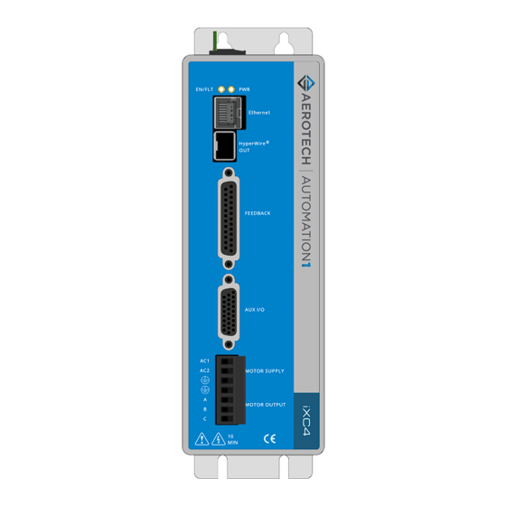
Figure 1-1: Ixc4 Digital Drive-Based Controller Labeled
Figure 1-2: XC4 Digital Drive Labeled
Table 1-1: Features and Options
Figure 1-3: Functional Diagram
Electrical Specifications
Table 1-2: Electrical Specifications
System Power Requirements
Mechanical Specifications
Mounting and Cooling
Table 1-3: Mounting Specifications
Dimensions
Figure 1-4: Dimensions
Figure 1-5: Dimensions [-EB1]
Environmental Specifications
Table 1-4: Environmental Specifications
Drive and Software Compatibility
Table 1-5: Drive and Software Compatibility
Chapter 2: Installation and Configuration
Input Power Connections
Control Supply Connector
Figure 2-1: Control Supply Connections
Table 2-1: Control Supply Wiring Specifications
Table 2-2: Mating Connector Part Numbers for the Control Supply Connector
Motor Supply Connector
Figure 2-2: Motor Supply Connections
Table 2-3: Motor Supply Connector Wiring Specifications
Table 2-4: Mating Connector Part Numbers for the Motor Supply Connector
Transformer Options
Table 2-5: Nominal Motor Operating Voltages / Required AC Voltages
Table 2-6: Transformer Options
Figure 2-3: TV0.3-28-56-ST Transformer Control and Motor Power Wiring (40 VDC Bus)
Figure 2-4: TV0.3-28-56-ST Transformer Control and Motor Power Wiring (80 VDC Bus)
Figure 2-5: TV0.3-28-56-ST Transformer Control and Motor Power Wiring (160 VDC Bus)
Figure 2-6: TV0.3-28 Transformer Control and Motor Power Wiring (40 VDC Bus)
Figure 2-7: TV0.3-56 Transformer Control and Motor Power Wiring (80 VDC Bus)
Figure 2-8: TM3/TM5 Transformer Control and Motor Power Wiring
Minimizing Noise for EMC/CE Compliance
Motor Power Output Connector
Table 2-7: Motor Power Output Connector Pinout
Table 2-8: Mating Connector Part Numbers for the Motor Power Output Connector
Brushless Motor Connections
Figure 2-9: Brushless Motor Configuration
Table 2-9: Wire Colors for Aerotech-Supplied Brushless Motor Cables
Brushless Motor Powered Motor and Feedback Phasing
Figure 2-10: Positive Motor Direction
Figure 2-11: Encoder and Hall Signal Diagnostics
Table 2-10: Hall Signal Diagnostics
Brushless Motor Unpowered Motor and Feedback Phasing
Figure 2-12: Brushless Motor Phasing Oscilloscope Example
Figure 2-13: Brushless Motor Phasing Goal
DC Brush Motor Connections
DC Brush Motor Phasing
Figure 2-14: DC Brush Motor Configuration
Figure 2-15: Positive Motor Direction
Table 2-11: Wire Colors for Aerotech-Supplied DC Brush Motor Cables
Stepper Motor Connections
Stepper Motor Phasing
Figure 2-16: Stepper Motor Configuration
Figure 2-17: Positive Motor Direction
Table 2-12: Wire Colors for Aerotech-Supplied Stepper Motor Cables
Three Phase Stepper Motor Connections
Stepper Motor Phasing
Figure 2-18: Three Phase Stepper Motor Configuration
Figure 2-19: Positive Motor Direction
Feedback Connector
Table 2-13: Feedback Connector Pinout
Table 2-14: Mating Connector Part Numbers for the Feedback Connector
Primary Encoder Inputs
Table 2-15: Multiplier Options
Table 2-16: Primary Encoder Input Pins on the Feedback Connector
Square Wave Encoder (Primary)
Figure 2-20: Square Wave Encoder Schematic (Feedback Connector)
Table 2-17: Square Wave Encoder Specifications
Absolute Encoder (Primary)
Figure 2-21: Absolute Encoder Schematic (Feedback Connector)
Sine Wave Encoder (Primary) [-MX1 Option]
Figure 2-22: Sine Wave Encoder Phasing Reference Diagram
Table 2-18: Sine Wave Encoder Specifications
Figure 2-23: Sine Wave Encoder Schematic (Feedback Connector)
Encoder Phasing
Figure 2-24: Encoder Phasing Reference Diagram (Standard)
Figure 2-25: Position Feedback in the Diagnostic Display
Hall-Effect Inputs
Figure 2-26: Hall-Effect Inputs Schematic (Feedback Connector)
Table 2-19: Hall-Effect Feedback Pins on the Feedback Connector
Thermistor Input
Figure 2-27: Thermistor Input Schematic (Feedback Connector)
Table 2-20: Thermistor Input Pin on the Feedback Connector
Encoder Fault Input
Figure 2-28: Encoder Fault Input Schematic (Feedback Connector)
Table 2-21: Encoder Fault Input Pin on the Feedback Connector
End of Travel and Home Limit Inputs
Table 2-22: End of Travel and Home Limit Pins on the Feedback Connector
Figure 2-29: End of Travel and Home Limit Input Connections
Figure 2-30: End of Travel and Home Limit Input Schematic (Feedback Connector)
End of Travel and Home Limit Phasing
Figure 2-31: End of Travel and Home Limit Input Diagnostic Display
Brake Outputs
Figure 2-32: Brake Connected to the 25-Pin Feedback Connector (Typical)
Table 2-23: Brake Output Pins on the Feedback Connector
Table 2-24: Brake Control Specifications
Safe Torque off Input (STO)
Table 2-25: STO Connector Pinout
Table 2-26: Mating Connector Part Numbers for the STO Connector
Figure 2-33: Typical STO Configuration
Table 2-27: STO Electrical Specifications
STO Standards
Table 2-28: STO Standards
Table 2-29: STO Standards Data
STO Functional Description
STO Startup Validation Testing
Table 2-30: STO Signal Delay
Table 2-31: Motor Function Relative to STO Input State
STO Diagnostics
Figure 2-34: STO Timing
Table 2-32: STO Timing
Auxiliary I/O Connector
Table 2-33: Auxiliary I/O Connector Pinout
Table 2-34: Mating Connector Part Numbers for the Auxiliary I/O Connector
Auxiliary Encoder Inputs
Table 2-35: Auxiliary Encoder Pins on the Auxiliary I/O Connector
Square Wave Encoder (Auxiliary)
Figure 2-35: Square Wave Encoder Interface (aux I/O Connector)
Absolute Encoder (Auxiliary)
Figure 2-36: Absolute Encoder Schematic (Auxiliary I/O Connector)
Position Synchronized Output (PSO)
Table 2-37: PSO Specifications
Table 2-38: PSO Pins on the Auxiliary I/O Connector
Figure 2-37: PSO Interface
Digital Outputs
Table 2-39: Digital Output Specifications
Table 2-40: Digital Output Pins on the Auxiliary I/O Connector
Figure 2-38: Digital Output Schematic (aux I/O Connector)
Figure 2-39: Digital Outputs Connected in Current Sourcing Mode
Figure 2-40: Digital Outputs Connected in Current Sinking Mode
Digital Inputs
Figure 2-41: Digital Inputs Schematic (aux I/O Connector)
Table 2-41: Digital Input Specifications
Table 2-42: Digital Input Pins on the Auxiliary I/O Connector
Figure 2-42: Digital Inputs Connected to Current Sourcing Devices
Figure 2-43: Digital Inputs Connected to Current Sinking Devices
High-Speed Inputs
Figure 2-44: High-Speed Inputs
Table 2-43: High-Speed Input Specifications
Table 2-44: High-Speed Input Pins on the Auxiliary I/O Connector
Analog Output
Figure 2-45: Analog Output 0 Schematic
Table 2-45: Analog Output Specifications
Table 2-46: Analog Output Pins on the Auxiliary I/O Connector
Analog Input 0 (Differential)
Figure 2-46: Analog Input 0 Schematic
Table 2-47: Analog Input Specifications
Table 2-48: Analog Input Pins on the Auxiliary I/O Connector
Brake Power Supply Connector
Table 2-49: Brake Power Supply Connector Pinout
Table 2-50: Mating Connector Part Numbers for the Brake Power Supply Connector
Hyperwire Interface
Table 2-51: Hyperwire Card Part Number
Table 2-52: Hyperwire Cable Part Numbers
External Shunt Option [-SX1]
Table 2-53: -SX1 Component Information
Table 2-54: Maximum Additional Storage Energy for a Standard Ixc4/Xc4
Sync Port
Table 2-55: Sync-Related Functions
Table 2-56: Sync Port Cables
System Interconnection
Figure 2-47: Drive-Based System Wiring Drawing (Best Practice)
Figure 2-48: PC-Based System Wiring Drawing (Best Practice)
Figure 2-49: Drive-Based Controller System Interconnection (Best Practice)
Figure 2-50: PC-Based Controller System Interconnection (Best Practice)
PC Configuration and Operation Information
Chapter 3: -EB1 I/O Option Board
Figure 3-1: -EB1 I/O Option Board Connectors (Ixc4 Shown)
Digital Outputs [-EB1]
Table 3-1: Digital Output Specifications [-EB1]
Table 3-2: Digital Output 1 Connector Pinout [-EB1]
Table 3-3: Mating Connector Part Numbers for the Digital Output 1 Connector [-EB1]
Table 3-4: Digital Output 2 Connector Pinout [-EB1]
Table 3-5: Mating Connector Part Numbers for the Digital Output 2 Connector [-EB1]
Figure 3-2: Digital Outputs Schematic [-EB1]
Figure 3-3: Digital Outputs Connected in Current Sourcing Mode [-EB1]
Figure 3-4: Digital Outputs Connected in Current Sinking Mode [-EB1]
Digital Inputs [-EB1]
Table 3-6: Digital Input Specifications [-EB1]
Table 3-7: Digital Input 1 Connector Pinout [-EB1]
Table 3-8: Mating Connector Part Numbers for the Digital Input 1 Connector [-EB1]
Figure 3-5: Digital Inputs Schematic [-EB1]
Table 3-9: Digital Input 2 Connector Pinout [-EB1]
Table 3-10: Mating Connector Part Numbers for the Digital Input 2 Connector [-EB1]
Figure 3-6: Digital Inputs Connected to Current Sourcing (PNP) Devices [-EB1]
Figure 3-7: Digital Inputs Connected to Current Sinking (NPN) Devices [-EB1]
Analog Outputs [-EB1]
Figure 3-8: Analog Output Typical Connection [-EB1]
Table 3-11: Analog Output Specifications [-EB1]
Table 3-12: Analog Output Connector Pinout [-EB1]
Table 3-13: Mating Connector Part Numbers for the Analog Output Connector [-EB1]
Analog Inputs [-EB1]
Figure 3-9: Analog Input Typical Connection [-EB1]
Table 3-14: Differential Analog Input Specifications [-EB1]
Table 3-15: Analog Input Connector Pinout [-EB1]
Table 3-16: Mating Connector Part Numbers for the Analog Input Connector [-EB1]
PSO Interface [-EB1]
Table 3-17: PSO Specifications [-EB1]
Table 3-18: PSO Interface Connector Pinout [-EB1]
Table 3-19: Mating Connector Part Numbers for the PSO Interface Connector [-EB1]
Figure 3-10: PSO Output Sources Current
Figure 3-11: PSO Output Sinks Current
Figure 3-12: PSO TTL Outputs Schematic
Chapter 4: Cables and Accessories
Table 4-1: Standard Interconnection Cables
Joystick Interface
Figure 4-1: Two Axis Joystick Interface (to the aux I/O of Two Drives)
Figure 4-2: Two Axis Joystick Interface (to the I/O Board)
Handwheel Interface
Chapter 5: Maintenance
Table 5-1: LED Description
Table 5-2: Troubleshooting
Preventative Maintenance
Table 5-3: Preventative Maintenance
Fuse Specifications
Table 5-4: Control Board Fuse Specifications
Appendix A: Warranty and Field Service
Appendix B: Revision History
Index
Table 2-36: Square Wave Encoder Specifications
Advertisement
Quick Links
Download this manual
Automation1 iXC4 and XC4
PWM Digital Drives
HARDWARE MANUAL
Revision 2.04
Table of
Contents
Previous
Page
Next
Page
1
2
3
4
5
Advertisement
Table of Contents
Need help?
Do you have a question about the Automation1 iXC4 and is the answer not in the manual?
Ask a question
Questions and answers
Related Manuals for Aerotech Automation1 iXC4
DC Drives Aerotech Automation1 XC6e Series Hardware Manual
High-powered pwm digital drive (110 pages)
DC Drives Aerotech Automation1 iXC6e Hardware Manual
High-powered pwm digital drives (112 pages)
DC Drives Aerotech Automation1 XC2 Hardware Manual
Pwm digital drive (96 pages)
DC Drives Aerotech Automation1 iXC2 Hardware Manual
Pwm digital drives (96 pages)
DC Drives Aerotech Automation1 iXL5e Hardware Manual
High-performance linear digital drives (112 pages)
DC Drives Aerotech Automation1 XL5e Hardware Manual
High-performance linear digital drive (110 pages)
DC Drives Aerotech Automation1 iXC4e Hardware Manual
Pwm high-performance digital drives (120 pages)
DC Drives Aerotech Automation1 XR3 Series Hardware Manual
Drive rack (104 pages)
DC Drives Aerotech Automation1 iXR3 Hardware Manual
Drive racks (112 pages)
DC Drives Aerotech Automation1 XL2e Hardware Manual
High-performance linear digital drives (96 pages)
DC Drives Aerotech Automation1 iXC2e Hardware Manual
Highperformance pwm digital drives (98 pages)
DC Drives Aerotech Automation1 XC2e Hardware Manual
Highperformance pwm digital drives (98 pages)
DC Drives Aerotech Automation1 iXL2e Hardware Manual
High-performance linear digital drives (96 pages)
DC Drives Aerotech Automation1 XC4 Hardware Manual
Pwm digital drives (120 pages)
DC Drives Aerotech Automation1 iXA4 Hardware Manual
Pwm digital drives (88 pages)
DC Drives Aerotech Automation1 XA4 Hardware Manual
Pwm digital drives (120 pages)
This manual is also suitable for:
Automation1 xc4
Table of Contents
Print
Rename the bookmark
Delete bookmark?
Delete from my manuals?
Login
Sign In
OR
Sign in with Facebook
Sign in with Google
Upload manual
Upload from disk
Upload from URL


Need help?
Do you have a question about the Automation1 iXC4 and is the answer not in the manual?
Questions and answers