Table of Contents
Advertisement
Quick Links
Advertisement
Table of Contents

Related Manuals for Aerotech Ndrive HP 10


Summary of Contents for Aerotech Ndrive HP 10
- Page 1 Artisan Technology Group is your source for quality new and certified-used/pre-owned equipment SERVICE CENTER REPAIRS WE BUY USED EQUIPMENT • FAST SHIPPING AND DELIVERY Experienced engineers and technicians on staff Sell your excess, underutilized, and idle used equipment at our full-service, in-house repair center We also offer credit for buy-backs and trade-ins •...
- Page 2 Ndrive HP 10/20/30 USER'S MANUAL P/N: EDU170 (Revision 1.14) Dedicated to the Science of Motion Aerotech, Inc. 101 Zeta Drive, Pittsburgh, PA, 15238 ph: 412-963-7470 fax: 412-963-7459 www.aerotech.com Artisan Technology Group - Quality Instrumentation ... Guaranteed | (888) 88-SOURCE | www.artisantg.com...
- Page 3 Revisoin 1.14 October 2, 2006 Product names mentioned herein are used for identification purposes only and may be trademarks of their respective companies. © Aerotech, Inc. 2005, 2006 Artisan Technology Group - Quality Instrumentation ... Guaranteed | (888) 88-SOURCE | www.artisantg.com...
-
Page 4: Table Of Contents
Ndrive HP 10/20/30 User’s Manual Table of Contents TABLE OF CONTENTS DECLARATION OF CONFORMITY ..........xi CHAPTER 1: INTRODUCTION ..........1-1 1.1. Feature Summary ..............1-2 1.2. Connection Overview..............1-3 1.3. Functional Diagram..............1-4 1.4. Ordering Information ..............1-5 1.5. Specifications ................1-7 1.5.1. Electrical Specifications ..........1-7 1.5.2. - Page 5 Table of Contents Ndrive HP 10/20/30 User’s Manual 3.1.4. High Speed User Inputs 12-13 (J205) ......3-6 3.1.5. Analog Input 0 (J205) ..........3-6 3.1.6. Analog Output 0 (J205)..........3-6 3.2. Position Synchronized Output (PSO) / Laser Firing ....3-7 3.2.1.
- Page 6 Ndrive HP 10/20/30 User’s Manual Table of Contents 6.4. Ndrive HP Power Board Assembly ...........6-5 6.5. LED Indicators................6-7 6.6. JTAG Programming Connector ..........6-8 6.7. Fuse / Battery Replacement .............6-9 6.8. Preventative Maintenance ............6-10 6.8.1. Cleaning ..............6-10 APPENDIX A: GLOSSARY OF TERMS ........A-1 APPENDIX B: WARRANTY and FIELD SERVICE....
- Page 7 Table of Contents Ndrive HP 10/20/30 User’s Manual ∇ ∇ ∇ www.aerotech.com Artisan Technology Group - Quality Instrumentation ... Guaranteed | (888) 88-SOURCE | www.artisantg.com...
- Page 8 Ndrive HP 10/20/30 User’s Manual List of Figures LIST OF FIGURES Figure 1-1. Ndrive HP 10/20/30 Networked Digital Drives ......1-1 Figure 1-2. Ndrive HP Hardware ..............1-3 Figure 1-3. Functional Diagram..............1-4 Figure 1-4. Ndrive HP Dimensions (with -IO Option) ........1-8 Figure 1-5.
- Page 9 List of Figures Ndrive HP 10/20/30 User’s Manual Figure 4-3. Analog Output Connector (TB301) ........... 4-3 Figure 4-4. Brake Connected to TB301 ............4-5 Figure 4-5. Brake Connected to J207 ............4-5 Figure 4-6. Suppression for DC Brake Systems ......... 4-6 Figure 4-7.
- Page 10 Ndrive HP 10/20/30 User’s Manual List of Tables LIST OF TABLES Table 1-1. Models, Options, and Voltage Configurations ......1-5 Table 1-2. Accessories................1-6 Table 1-3. Electrical Specifications ............1-7 Table 2-1. Ferrite Bead Part Numbers ............2-2 Table 2-2. TB101 Auxiliary AC Supply Input (when TB102 AC input <...
- Page 11 List of Tables Ndrive HP 10/20/30 User’s Manual Table 4-12. PSO / Absolute Encoder Interface Connector Pin Assignment (J301) ..............4-13 Table 4-13. PSO / Absolute Encoder Mating Connector (J301) ....4-13 Table 4-14. Laser Output Opto-Isolator Specifications......4-14 Table 4-15. J302, J303 2-Channel SSI Net Connector Pin Assignment ................4-16...
-
Page 12: Declaration Of Conformity
Manufacturer’s Name Aerotech, Inc. and Address: 101 Zeta Drive Pittsburgh, PA 15238-2897 Declares that the product: Ndrive HP 10/20/30 Conforms to the following product specifications, with the exceptions listed below. EMC: EN 61800-3:1997 EMC requirements for power drives EN 61326-1:1997... - Page 13 Control and Emergency Stop requirements are to be determined and provided by the end user. • Wire and cabling provided with the Ndrive meet Aerotech’s electrical and listed environmental requirements. The end user must meet the final requirements. Failure to follow these procedures may result in serious injury, damage and/or excessive emissions or reduced immunity of the equipment.
-
Page 14: Chapter 1: Introduction
Ndrive HP 10/20/30 User’s Manual Introduction CHAPTER 1: INTRODUCTION Aerotech’s Network Digital Drives (Ndrive HP) complement the Automation 3200 ® System (see Figure 1-1). Connected via the IEEE-1394 (FireWire ) communication bus, these drives provide deterministic behavior, auto-identification, and easy software setup from the Nmotion SMC software controller. -
Page 15: Feature Summary
Introduction Ndrive HP 10/20/30 User’s Manual 1.1. Feature Summary • Software configurable for brush, brushless and stepper motor operation • Standard 100 VDC – 320 VDC Bus, optional 20 VDC – 80 VDC Bus, requires the -AUXPWR option • Fully isolated power stage •... -
Page 16: Connection Overview
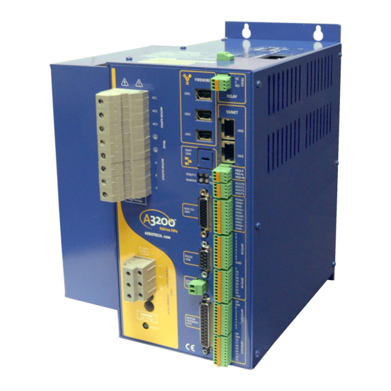
Ndrive HP 10/20/30 User’s Manual Introduction 1.2. Connection Overview The Ndrive HP consists of two power connections (motor power and input power), three FireWire ports, an optional Ethernet connection, an RS-232/RS-422 connector, LED indicator lamps and two D-Style connectors for Auxiliary I/O (15 and 26 pin) and Motor Feedback (25 pin). -
Page 17: Functional Diagram
Introduction Ndrive HP 10/20/30 User’s Manual 1.3. Functional Diagram The standard package includes the bus power supply that operates from 85-250 VAC (120 – 350 VDC). The power supply is included with the standard package for off-line operation without the need for an isolation transformer. A soft start circuit is included to prevent high inrush currents. -
Page 18: Ordering Information
Ndrive HP 10/20/30 User’s Manual Introduction 1.4. Ordering Information The Ndrive HP is available in three models with continuous power, ranging from 1,360 to 4,080 watts. A list of these models, and the available voltage configurations, are shown in Table 1-1. See Table 1-2 for a list of available accessories. -
Page 19: Table 1-2. Accessories
Introduction Ndrive HP 10/20/30 User’s Manual Table 1-2. Accessories Accessories TV0.3-28 0.3 kVA autotransformer; 28 or 56 VAC out for 40 or 80 VDC bus, 115/230 VAC, 50/60 Hz input TV0.3-56 0.3 kVA autotransformer; 56 or 115 VAC out for 80 or 160 VDC bus, 115/230 VAC, 50/60 Hz input TV1.5... -
Page 20: Specifications
Ndrive HP 10/20/30 User’s Manual Introduction 1.5. Specifications 1.5.1. Electrical Specifications Table 1-3. Electrical Specifications Description Units Ndrive HP 10 Ndrive HP 20 Ndrive HP 30 Main Supply Input Voltage 240 VAC Max. (Single or 3 Phase) Main Supply Input Frequency... -
Page 21: Mechanical Specifications
Introduction Ndrive HP 10/20/30 User’s Manual 1.5.2. Mechanical Specifications The outline dimensions for the Ndrive HP are shown in Figure 1-4 and Figure 1-5. Units should be separated from each other and surrounded by one inch of free air space. -
Page 22: Figure 1-5. Ndrive Hp Dimensions (Without The -Io Option)
Ndrive HP 10/20/30 User’s Manual Introduction Figure 1-5. Ndrive HP Dimensions (without the -IO Option) The Ndrive HP case temperature may exceed 75°C in some applications. www.aerotech.com Artisan Technology Group - Quality Instrumentation ... Guaranteed | (888) 88-SOURCE | www.artisantg.com... -
Page 23: Environmental Specifications
Introduction Ndrive HP 10/20/30 User’s Manual 1.5.3. Environmental Specifications The environmental specifications for the Ndrive HP are listed below. • Ambient Temperature: Operating - 5° - 40°C (41° - 104°F) ° ° Storage - -20 - 70 C (-4 - 158 Maximum relative humidity is 80% for temperatures up •... -
Page 24: Chapter 2: Installation And Configuration
Ndrive HP 10/20/30 Manual Installation and Configuration CHAPTER 2: INSTALLATION and CONFIGURATION This section covers the hardware configurations using the switches, jumpers, connectors, and power connections when used with a brush, brushless, or stepper motor. Wiring, grounding, shielding techniques, and the motor phasing process are also covered. -
Page 25: Wiring, Grounding, And Shielding Techniques
4. If possible, do not route motor cables near cables carrying logic signals and use shielded cable to carry logic signals. 5. Ferrite beads or Aerotech’s FBF-1 or FBF-2 filter adapters, may be used on the motor leads to reduce the effects of amplifier EMI/RFI, produced by PWM (pulse width modulation) amplifiers. -
Page 26: Minimizing 50/60 Hz Line Interference
Ndrive HP 10/20/30 Manual Installation and Configuration 2.2.2. Minimizing 50/60 HZ Line Interference Operating the Ndrive HP from an off-line source of 115 VAC or 230 VAC may create some additional issues. There is a potential problem of EMI generated from the switching power stage of the Ndrive propagating through the bridge rectifier and out through the AC1 and AC2 input AC line connections. -
Page 27: Power Connections
AC power board. The connection is made to the AC input board with a three terminal connector (Aerotech Part #ECK00213), provided. See Section 2.4. for various typical AC wiring options. TB101 is also typically utilized when an emergency stop circuit is present. -
Page 28: Motor Power Connections (Tb102)
Ndrive HP 10/20/30 Manual Installation and Configuration 2.3.2. Motor Power Connections (TB102) The three-phase motor terminal connections are made at connections A, B, and C. Motor Connections ØA, ØB, ØC and its Protective Ground should be made with 1.62814 mm (#14 AWG) wire rated at 300 V. -
Page 29: 40/80 Vdc Power Transformers
Installation and Configuration Ndrive HP 10/20/30 Manual 2.3.3. 40/80 VDC Power Transformers The TV0.3-56 power transformer is an optional accessory for the Ndrive HP. The transformer allows the generation of 56 VAC from a 115 VAC and 230 VAC source respectively. -
Page 30: Typical Ac Wiring With Auxpwr Option
Ndrive HP 10/20/30 Manual Installation and Configuration 2.4. Typical AC Wiring with AUXPWR Option The user may connect an Ndrive to a 115/230 VAC source and generate a 40, 80 160 VDC Bus for the motor power. The following three figures illustrate the six combinations available for both AC input voltages and all three DC bus voltages, as well as the use of the -AUXPWR option. - Page 31 Installation and Configuration Ndrive HP 10/20/30 Manual Ndrive HP PRIMARY FUSE AUXPWR OPTION 4A SLO-BLO #18 WHT TRANSFORMER AC HI INTERNAL 115VAC THERMAL splice AC LO 50/60 HZ #18 WHT SWITCH INPUT RED 56v 115v BLK SAFTEY 100v ORN GRN 0v...
- Page 32 Ndrive HP 10/20/30 Manual Installation and Configuration Ndrive HP PRIMARY FUSE AUXPWR OPTION 4A SLO-BLO #18 WHT TRANSFORMER AC HI INTERNAL 115VAC THERMAL splice AC LO 50/60 HZ #18 WHT SWITCH NOTES: INPUT RED 56v 115v BLK SAFTEY 1. THE AUXPWR OPTION IS USED...
-
Page 33: Motor And Feedback Connections
2.5.1. DC Brush Motor in Torque Mode Configuration The DC brush motor configuration is shown in Figure 2-9. See Section 2.6.1 for the correct encoder phasing information if Aerotech’s standard cabling is not used. Figure 2-9. DC Brush Motor (Torque Mode) Configuration 2-10 www.aerotech.com... -
Page 34: Dc Brush Motor Phasing
Ndrive HP 10/20/30 Manual Installation and Configuration 2.5.1.1. DC Brush Motor Phasing If an Aerotech motor is used with Aerotech provided cabling, no motor phasing process is required. A DC brush motor is phased correctly when a positive motion command causes clockwise (CW) motor rotation, as viewed looking at the motor from the front mounting flange. -
Page 35: Dc Brush Motor With Tachometer Feedback Configuration
The DC brush motor configuration is shown in Figure 2-10. See section 2.6.1 for the correct encoder phasing information if Aerotech’s standard cabling is not used. The tachometer may be connected to TB302 or J205 as shown in the picture below. Note, that tachometer feedback uses analog input 0, so it may not be used when tachometer feedback is used. -
Page 36: Brushless Motor Configuration
Ndrive HP 10/20/30 Manual Installation and Configuration 2.5.3. Brushless Motor Configuration This mode is used with a brushless motor only. See Section 2.6., if Aerotech’s standard cabling is not used, for information on correctly phasing the motor, encoder, and Hall feedback devices. -
Page 37: Brushless Motor Phasing
When configuring the Ndrive HP to run a non-Aerotech brushless motor, the motor leads (A, B and C on TB102) must be correctly connected for proper operation. If an Aerotech motor is used with Aerotech provided cabling, no motor phasing process is required. -
Page 38: Brushless Motor Hall-Effect Feedback Connections
Ndrive HP 10/20/30 Manual Installation and Configuration 2.5.3.2. Brushless Motor Hall-Effect Feedback Connections The Hall-Effect feedback signals on an AC brushless motor are correctly phased when the hall states correspond to the states at each of the electrical angles shown in Figure 2- 14 The Hall states, which correspond to the electrical angles, are indicated in Figure 2-14 A “0”... -
Page 39: Hall-Effect Phasing
Installation and Configuration Ndrive HP 10/20/30 Manual 2.5.3.3. Hall-Effect Phasing For an AC brushless motor with an unknown hall sequence, one of two simple tests can be performed on the motor to determine the proper connections to the Ndrive HP. -
Page 40: Figure 2-14. Motor Phasing
Ndrive HP 10/20/30 Manual Installation and Configuration Figure 2-14. Motor Phasing www.aerotech.com 2-17 Artisan Technology Group - Quality Instrumentation ... Guaranteed | (888) 88-SOURCE | www.artisantg.com... -
Page 41: Stepper Motor Configuration
Installation and Configuration Ndrive HP 10/20/30 Manual 2.5.4. Stepper Motor Configuration This mode is used with a stepper motor only. See Section 2.6.1, if Aerotech’s standard cabling is not used, for information on correctly phasing the motor feedback devices. Figure 2-15. -
Page 42: Encoder Feedback Connections
DC Brush and brushless motors may have a separate position and a velocity feedback device. An analog sine wave encoder may be used with Aerotech’s MXH multiplier box to multiply the encoder resolution and simultaneously convert it to a differential line driver encoder signal, acceptable by the Ndrive HP. -
Page 43: Encoder Phasing
Installation and Configuration Ndrive HP 10/20/30 Manual 2.6.1. Encoder Phasing Figure 2-17 illustrates the required encoder phasing for clockwise motor rotation, or positive forcer movement through the stationary magnet track. If the motor is not visible, or may not be manually moved by hand, it may be actively driven open loop, under program control, by running the A3200\Programs\Samples\MsetDebug.Pgm program. -
Page 44: End Of Travel (Eot) Limit Input Connections
Ndrive HP 10/20/30 Manual Installation and Configuration 2.7. End of Travel (EOT) Limit Input Connections End of Travel (EOT) Limits are required to define the end of the physical travel. They are also used for homing, which defines an absolute reference for the user coordinate system. -
Page 45: Communication Channel Settings
Installation and Configuration Ndrive HP 10/20/30 Manual 2.8. Communication Channel Settings Each Ndrive HP must have a unique communication channel number defined by switch S2. It is recommended that they be sequential beginning with the first device number. The 1 device as indicated by the switch settings in row 1 of the following table will be configured by the Axis 1 parameters in the Nparam utility. -
Page 46: Connecting Multiple Drives
Ndrive HP 10/20/30 Manual Installation and Configuration 2.9. Connecting Multiple Drives Following are two interconnection diagrams and a chart showing the part numbers of the FireWire Bus PCI card and the various interconnect cables and their part numbers. Table 2-5. -
Page 47: I/O And Signal Wiring Requirements
Installation and Configuration Ndrive HP 10/20/30 Manual Figure 2-22. FireWire Daisy Chain Before connecting any device to the FireWire bus, the device should be powered up and tested independently to prevent damaging linked equipment. Ndrive HPs, HLs, CPs, MPs, Nservos, Nsteps and Npaqs... -
Page 48: Emergency Stop Sense Input (Tb201)
Ndrive HP 10/20/30 Manual Installation and Configuration 2.10. Emergency Stop Sense Input (TB201) This input is to be activated by an external fail-safe emergency stop circuit. It is not intended to be an emergency stop circuit in itself. It is scaled for an input voltage of 5-24 volts. -
Page 49: Typical Estop Interface
Installation and Configuration Ndrive HP 10/20/30 Manual 2.10.1. Typical ESTOP Interface The user may connect an emergency stop circuit to the Ndrive. It will disable power to the motor by removing power to the power stage of the drive, while maintaining power to the control section, as shown in the following Figure 2-24. -
Page 50: Pc Configuration And Operation Information
Ndrive HP 10/20/30 Manual Installation and Configuration 2.11. PC Configuration and Operation Information The Getting Started Guide (PN: EDU175) included with the Nmotion SMC’s software package, provides a quick start guide with basic information. The Nview help included with the software provides additional information for configuring the Ndrive HP to the PC as well as information on hardware requirements, getting started, utilities and system operation, and on using the Nview HMI user application. - Page 51 Installation and Configuration Ndrive HP 10/20/30 Manual 2-28 www.aerotech.com Artisan Technology Group - Quality Instrumentation ... Guaranteed | (888) 88-SOURCE | www.artisantg.com...
-
Page 52: Chapter 3: Technical Details
Ndrive HP 10/20/30 User’s Manual Technical Details CHAPTER 3: TECHNICAL DETAILS 3.1. Auxiliary I/O Connector (J205) The J205, Auxiliary I/O connector provides 6 inputs, 4 outputs and a secondary bi- directional RS-422 line driver encoder interface. See the following sub-sections for details on each type of signal within the J205 connector. -
Page 53: Secondary Encoder Channel (J205)
Technical Details Ndrive HP 10/20/30 User’s Manual Table 3-2. Auxiliary I/O Connector Mating Connector (J205) Aerotech Third Party Source Connector ECK01259 Kycon K86-AA-26P Back shell ECK00600 Cinch DA24658 Screw Locks, Qty. 2 EIZ00294 TRW D-20419-16 All of the external power provided by the Ndrive HP to the user is limited to 500 mAmps and protected by a re-settable fuse. -
Page 54: Figure 3-1. Secondary Encoder Channel (J205)
Ndrive HP 10/20/30 User’s Manual Technical Details Figure 3-1. Secondary Encoder Channel (J205) www.aerotech.com Artisan Technology Group - Quality Instrumentation ... Guaranteed | (888) 88-SOURCE | www.artisantg.com... -
Page 55: User Outputs 8-11 (J205)
Technical Details Ndrive HP 10/20/30 User’s Manual 3.1.2. User Outputs 8-11 (J205) All outputs (Figure 3-2) are rated for 40 volts and 80 mAmps per channel. Power dissipation may not exceed 90 mWatts per channel. * Output 11, shown in the following Figure, may be defined as a low-speed PSO (Laser Firing output), however, it is only rated for a maximum output frequency of 1 kHz, with a typical propagation delay of 250 us. -
Page 56: User Inputs 8-11 (J205)
Ndrive HP 10/20/30 User’s Manual Technical Details 3.1.3. User Inputs 8-11 (J205) Inputs 8-11, as shown in Figure 3-3, are scaled for an input voltage of 5-24 volts. A higher input voltage requires adding external series resistors to limit the current to 20 milliamps. -
Page 57: High Speed User Inputs 12-13 (J205)
Technical Details Ndrive HP 10/20/30 User’s Manual 3.1.4. High Speed User Inputs 12-13 (J205) The high-speed inputs shown in Figure 3-3, are scaled for a 5 volt input voltage. A higher input voltage requires adding an external series resistor to limit the current to 7 milliamps. -
Page 58: Position Synchronized Output (Pso) / Laser Firing
Ndrive HP 10/20/30 User’s Manual Technical Details 3.2. Position Synchronized Output (PSO) / Laser Firing The Ndrive includes a Position Synchronized Output (PSO or Laser Firing) option. This feature may be programmed to generate an output synchronized to axes positions, based upon a user-defined trigger condition, most typically, but not limited to firing a laser. -
Page 59: Table 3-10. Pso Output Sources
Technical Details Ndrive HP 10/20/30 User’s Manual Table 3-10. PSO Output Sources Maximum Standard Requires User PSO Output Type Frequency Option Isolation High Speed Opto-Isolator - J301 Table 4-14 -IOPSO option Opto-Isolated Output 11 - J205 1 KHz Standard RS-422... -
Page 60: Figure 3-5. Advanced 1 - 3 Axis Firing
Ndrive HP 10/20/30 User’s Manual Technical Details Figure 3-5. Advanced 1 - 3 Axis Firing The Data Capture and Data Update modes allow data to be captured or written to the I/O on the occurrence of the internal or external trigger. Data Capture mode allows position, digital inputs, etc. -
Page 61: Single Axis Laser Firing
Technical Details Ndrive HP 10/20/30 User’s Manual Figure 3-6. Data Capture/Data Update Modes 3.2.1. Single Axis Laser Firing Single axis firing requires no additional encoder signals and is capable of tracking the axis position at up to a 20 MHz. tracking rate (50 nsec. minimum edge separation). It may be programmed to fire from any available encoder source, see Table 3-9. -
Page 62: Motor Feedback (J207)
This connector has inputs for a 3-channel encoder, three limit switches, and three Hall-effect devices. Each of these inputs provides feedback for the DSP microprocessor controlled position, velocity and current loops. See Section 2.6.1 Encoder Phasing for information on interfacing non-Aerotech motors. Table 3-11. Motor Feedback Connector Pin Assignment (J207) -
Page 63: End Of Travel Limit Inputs
Technical Details Ndrive HP 10/20/30 User’s Manual 3.3.1. End of Travel Limit Inputs Two of the three limit inputs are end-of-travel sensing (CW Limit and CCW Limit) while the third is a reference limit (Home Limit). All of the end of travel limit inputs accept 5- 24 VDC logic signals. -
Page 64: Hall Effect And Thermistor Inputs
Ndrive HP 10/20/30 User’s Manual Technical Details 3.3.2. Hall Effect and Thermistor Inputs The Hall-effect switch inputs are highly recommended for AC brushless motor commutation but not absolutely required; see the Nview help for more information on axis configuration. The Hall-effect inputs accept 5-24 volt DC logic signals. The Pin Assignment for the connector is shown in the table below. -
Page 65: Brake Output
MXH option (see Section 3.3.4.2 for more information). See Section 2.6.1. Encoder Phasing for information on interfacing non-Aerotech motors. See Table 3-12 for the mating connector part number. -
Page 66: Line Driver Encoder (Standard)
Ndrive HP 10/20/30 User’s Manual Technical Details 3.3.4.1. Line Driver Encoder (Standard) The primary encoder input is standardly configured for a differential line driver encoder, in the range of 0 to +5 volts. It allows up to an 8 MHz encoder signal (31 nsec minimum edge separation), producing 32 million counts per second, after times four (x4) quadrature decoding. -
Page 67: Mxh Option
Technical Details Ndrive HP 10/20/30 User’s Manual 3.3.4.2. MXH Option The MXH encoder input options are defined for a differential analog encoder in the range of 0 to +5 volts. The maximum encoder input frequency is limited to 200 kHz, or less if the encoder signals are to be output via the SSI Net, see Table 3-17. -
Page 68: Table 3-17. Mxh Option Specifications
Ndrive HP 10/20/30 User’s Manual Technical Details Table 3-17. MXH Option Specifications Applicable only when signals are output via the SSI Net CfgFbkEncMult- Total FactorMXH Axis Multiplication Clock Freq. Max Input Min Edge Min Pulse (1,2) Parameter Freq (kHz) Separation (µs) Width (µs) -
Page 69: Figure 3-10. Optional Mxh Analog Encoder Interface (J207)
Technical Details Ndrive HP 10/20/30 User’s Manual Figure 3-10. Optional MXH Analog Encoder Interface (J207) 3-18 www.aerotech.com Artisan Technology Group - Quality Instrumentation ... Guaranteed | (888) 88-SOURCE | www.artisantg.com... -
Page 70: Rs-422 Port (J206)
Ndrive HP 10/20/30 User’s Manual Technical Details 3.4. RS-232 / RS-422 Port (J206) The RS-232C and RS-422 (factory option) ports may not be used simultaneously. They are one physical port, converted to each interface by the appropriate line driver/receiver, as shown in Figure 3-11. Connecting the RS-232 port to a user’s PC requires only a standard 9-pin cable (not a null modem). -
Page 71: Figure 3-11. Rs-232/Rs-422 Connector (J206)
Technical Details Ndrive HP 10/20/30 User’s Manual Figure 3-11. RS-232/RS-422 Connector (J206) 3-20 www.aerotech.com Artisan Technology Group - Quality Instrumentation ... Guaranteed | (888) 88-SOURCE | www.artisantg.com... -
Page 72: Firewire Bus (J201, J202, J203)
Ndrive HP 10/20/30 User’s Manual Technical Details 3.5. FireWire Bus (J201, J202, J203) The FireWire bus is the high-speed communications media to the Ndrive, operating at 400 megabits per second. All command and configuration information is sent via the FireWire. All three ports are effectively in parallel, allowing any port to be used when daisy-chaining the Ndrive HPs together or with other devices such as the Npaq (as shown in Figure 2-22). -
Page 73: Voltage-To-Current Mode Operation
Technical Details Ndrive HP 10/20/30 User’s Manual 3.6. Voltage-to-Current Mode Operation The firmware (version 2.06 and later) on the Ndrive supports a voltage-to-current mode. This mode allows the unit to run in a standalone mode, attached to a master position/velocity loop controller. -
Page 74: Parameter Setup And Hardware Configuration
Ndrive HP 10/20/30 User’s Manual Technical Details 3.6.1. Parameter Setup and Hardware Configuration Setup for the Voltage-to-Current mode should be performed using the Automation 3200 SMC. This software interface should be used to configure the parameters on the drive. The parameters of principal concern are: Current Loop Parameters (gains, offsets, etc.) -
Page 75: Operation
Technical Details Ndrive HP 10/20/30 User’s Manual 3.6.3. Operation In the Voltage-to-Current mode, the Ndrive acts as a simple voltage-to-current controller. Analog Input 0 provides the current/torque command. Analog input 0 is accessible through either the -IOPSO option board or the J205 connector. -
Page 76: Options
Ndrive HP 10/20/30 User’s Manual Options CHAPTER 4: OPTIONS 4.1. –IOPSO and –IOPSOH Option Boards See the following sections for details on the connector Pin Assignment and technical information for the –IOPSO and –IOPSOH options. The –IOPSO expansion board has 8 opto-isolated inputs (sinking or sourcing) and 8... -
Page 77: Brake Configuration Jumpers
Ndrive HP Options Ndrive HP 10/20/30 User’s Manual The -IOPSOH expansion board has 8 opto-isolated inputs (sinking or sourcing) and 8 outputs (sinking or sourcing ) rated at 1 A per channel, two 18-bit analog outputs, two 16-bit differential analog inputs, SSI Net, absolute encoder interface and brake relay, and includes a HCPL2601 opto-isolator. -
Page 78: Analog Outputs (Tb301)
Ndrive HP 10/20/30 User’s Manual Options 4.1.2. Analog Outputs (TB301) Both analog outputs are driven by an 18-bit AD1868 digital to analog converter and buffered by TL084 op-amps, producing a single-ended output voltage in the range of ± 10 volts. This produces a resolution of 76.3 uVolts per bit of the D/A. The output current is limited to less than 50 mA. -
Page 79: Brake / Relay (Tb301)
Ndrive HP Options Ndrive HP 10/20/30 User’s Manual 4.1.3. Brake / Relay (TB301) The relay output is typically used to automatically drive a fail-safe brake on a vertical axis, however, it may also be used as a general purpose relay. See the... - Page 80 Ndrive HP 10/20/30 User’s Manual Options Figure 4-4 is an example of a 24 VDC Brake connected to TB301. In this example, JP1- A and JP1-B must be configured. If JP1-A and JP1-B are configured to 1-3 then J207 pins 13 and 25 will be unused. If JP1-A is set 1-2 and JP1-B is set 3-4, a connection between pins 13 and 25 of J207 is required.
-
Page 81: Figure 4-6. Suppression For Dc Brake Systems
Ndrive HP Options Ndrive HP 10/20/30 User’s Manual Step #3 Suppression and Snubber requirements Due to the inductive effects of the brake, suppression and/or snubber, components are needed to reduce arcing and prevent damage to the Brake Relay contacts. Suppression can also reduce the electrical noise that is emitted when the circuit is switched off. -
Page 82: Figure 4-7. Suppression For Ac And Dc Brake Systems
Ndrive HP 10/20/30 User’s Manual Options Example #3: Figure 4-7 is a suppression circuit that can be used for both AC and DC circuits. In this method, a resistor, capacitor and a varistor are used across the load (see Figure 4-7). In some cases, better results are obtained by installing the suppression devices across the relay contacts. -
Page 83: Analog Inputs (Tb302)
Ndrive HP Options Ndrive HP 10/20/30 User’s Manual 4.1.4. Analog Inputs (TB302) Both analog inputs are differential, buffered by a precision unity gain differential INA105 amplifier and converted to digital by a 16-bit ADS8320 analog to digital converter allowing an input voltage in the range of ±10 volts. This produces a resolution of 305 uVolts per bit of the A/D. -
Page 84: User Power Connector (Tb303)
Ndrive HP 10/20/30 User’s Manual Options 4.1.5. User Power Connector (TB303) This connector provides access to the Ndrive HPs internal power supply, which may be used to power external devices (500 mAmps maximum). It also provides a connection to power the opto-isolated PSO (Laser Firing) output (see Figure 4-14). -
Page 85: Figure 4-9. Connecting Outputs In Current Sinking Mode
Ndrive HP Options Ndrive HP 10/20/30 User’s Manual Figure 4-9. Connecting Outputs in Current Sinking Mode Figure 4-10. Connecting Outputs in Current Sourcing Mode Suppression diodes must be installed on outputs that are used to drive relays or other inductive devices to protect the output devices from being damaged by the inductive spikes that occur when the device is turned off. -
Page 86: Opto-Isolated Inputs (Tb305)
Ndrive HP 10/20/30 User’s Manual Options 4.1.7. Opto-Isolated Inputs (TB305) The inputs are configured for 5-24 volt logic, using a higher input voltage, requires adding external series resistors to limit the current. The opto-isolator is a PS2506L-4 device. The inputs may be connected to current sourcing or current sinking devices, as shown in Figure 4-11 and Figure 4-12. -
Page 87: Figure 4-12. Inputs Connected In Current Sourcing Mode
Ndrive HP Options Ndrive HP 10/20/30 User’s Manual Figure 4-12. Inputs Connected in Current Sourcing Mode 4-12 www.aerotech.com Artisan Technology Group - Quality Instrumentation ... Guaranteed | (888) 88-SOURCE | www.artisantg.com... -
Page 88: Pso / Absolute Encoder Interface (J301)
Ndrive HP 10/20/30 User’s Manual Options 4.1.8. PSO / Absolute Encoder Interface (J301) This connector utilizes the RS-485 port and the (analog sine wave) encoder channel as an absolute encoder interface. The absolute encoder channel accepts a differential analog encoder up to 200 kHz. Typically, this is a 1 Volt P-P signal varying about a 2.5 Volt reference. -
Page 89: Figure 4-13. Absolute Encoder Interface (J301)
Ndrive HP Options Ndrive HP 10/20/30 User’s Manual Table 4-14. Laser Output Opto-Isolator Specifications Power Supply Output M12 Device (Option#) Nominal Propagation Voltage Current Frequency Delay (Typ.) See Figure 4-14 Sink Laser .05 us. * HCPL-2601 5 MHz 5 VDC... -
Page 90: Figure 4-14. Pso Interface
Ndrive HP 10/20/30 User’s Manual Options Figure 4-14. PSO Interface Output 11 and the Auxiliary Marker on J205 (pins 19 and 20) may also be defined as the PSO Laser Firing output via the PSOCONTROL command. See Section 3.2 for connection and other information. -
Page 91: Ssi Net (2 Channels) (J302, J303)
Ndrive HP Options Ndrive HP 10/20/30 User’s Manual 4.1.9. SSI Net (2 channels) (J302, J303) Each of the two SSI Net interfaces is a two-channel bidirectional RS-422 interface, most typically for quadrature encoders. This allows one channel for the sine signal and one channel for the cosine signal. - Page 92 Ndrive HP 10/20/30 User’s Manual Options Figure 4-16. J301/J302/J303 www.aerotech.com 4-17 Artisan Technology Group - Quality Instrumentation ... Guaranteed | (888) 88-SOURCE | www.artisantg.com...
-
Page 93: Dualpso And -Triplepso Laser Firing Options
Ndrive HP Options Ndrive HP 10/20/30 User’s Manual 4.2. –DUALPSO and –TRIPLEPSO Laser Firing Options The Ndrive HP allows two and three-axis laser firing via its -DUALPSO and - TRIPLEPSO options. To accomplish this, the encoder signals from a second/third Ndrive must be jumpered (or daisy-chained) from that Ndrive to the Ndrive with the - DUALPSO or -TRIPLEPSO options. -
Page 94: Pso Tracking Rate Configuration
Ndrive HP 10/20/30 User’s Manual Options 4.2.1. PSO Tracking Rate Configuration PSO Track Rate Configuration applies to an Ndrive with either the -DUALPSO or -TRIPLEPSO options, and the MXH option, with high encoder data rates. A) The maximum clock frequency of the MXH multiplier should be limited to 20 MHz. - Page 95 Ndrive HP Options Ndrive HP 10/20/30 User’s Manual Example: It is desired to generate a pulse output every 1,000 encoder counts in -DUALPSO or -TRIPLEPSO mode. The individual axis speeds approach 20 MHz. during the motion and therefore exceed the 5 MHz. -DUALPSO or -TRIPLEPSO tracking limitation.
-
Page 96: Enet (Ethernet) Option J204
Ndrive HP 10/20/30 User’s Manual Options 4.3. –ENET (Ethernet) Option J204 The optional Ethernet port provides connectivity to a 10/100Base-T ModBus TCP network. This is typically used for adding analog and digital I/O to the controller. See the Ethernet I/O help on the Window’s Start bar on the Automation 3200 menu. -
Page 97: Rdp Resolver Input
Ndrive HP Options Ndrive HP 10/20/30 User’s Manual 4.4. –RDP Resolver Input The optional resolver input provides two industry standard resolver or Inductosyn channels, which may each be used as a feedback device. Each may be separately configured for resolver or inductosyn input, as shown in Table 4-21. The standard reference output frequency is 10 kHz., optionally it may be configured as 5 or 7.5 kHz.,... -
Page 98: Figure 4-20. Resolver Option Assembly (690D1599 Rev. 0)
Ndrive HP 10/20/30 User’s Manual Options Table 4-22. Resolver Test Points Test Point Number Description Signal Common TP10 Sine input Channel 1 TP11 Cosine input Channel 1 TP12 Reference signal Channel 1 TP20 Sine input Channel 2 TP21 Cosine input Channel 2... -
Page 99: Resolver/Inductosyn Setup
90 degrees. For most inductosyns, this value will need to be varied from system to system to optimize performance. See Figure 4-22 below for example phasing. Note that some Aerotech systems may have an optional pre-amplifier board. This may be installed within the mechanics itself, as is the case with an Aerotech AOM360D optical mount. -
Page 100: Configuring The Analog Feedback Signals
Ndrive HP 10/20/30 User’s Manual Options Figure 4-21. Analog Output Connector (TB301) 4.4.1.2. Configuring the Analog Feedback Signals Using the Encoder Feedback Configuration Utility to set up a resolver / inductosyn The RDP option of the Ndrive can be optimally aligned quickly, using the Encoder Feedback Configuration utility within the Nscope.exe utility. - Page 101 Ndrive HP Options Ndrive HP 10/20/30 User’s Manual When to use the CfgFbkRDCosPhase axis Parameter: The Cosine reference signal can be adjusted from approximately 0 degrees (i.e. in phase with the SINE reference signal) to 180 degrees, with a nominal value of 90 degrees. This axis parameter is primarily for use with inductosyns, which have a nominal phase shift from the reference signal of 90 degrees.
-
Page 102: Figure 4-22. Resolver Located At Maximum Of Sin Signal
Ndrive HP 10/20/30 User’s Manual Options Figure 4-22. Resolver Located at Maximum of SIN Signal Figure 4-23. Rotating the Resolver (to see a circle) www.aerotech.com 4-27 Artisan Technology Group - Quality Instrumentation ... Guaranteed | (888) 88-SOURCE | www.artisantg.com... - Page 103 Ndrive HP Options Ndrive HP 10/20/30 User’s Manual For this to function, you MUST have the proper jumper set to 2-3 for this channel and the bit in the CfgFbkRDConfig axis parameter set to 1. Otherwise, erratic results may occur.
-
Page 104: Configuring The Commutation Initialization
Ndrive HP 10/20/30 User’s Manual Options 4.4.1.3. Configuring the Commutation Initialization The commutation of brushless motors with resolver feedback may be initialized two ways. The first method uses the number of motor pole pairs combined with the maximum resolution of the R/D board to determine an initial commutation position. The second method initializes the motor normally using the Hall-effect feedback signals. - Page 105 Ndrive HP Options Ndrive HP 10/20/30 User’s Manual Finding the Proper Commutation Offset in R/D Auto-Configuration Mode The R/D Auto-Configuration mode assumes that the zero crossing of the R/D Converter is aligned with the 0 angle of commutation on the Ndrive. Therefore, to determine the...
-
Page 106: Accessories
Ndrive HP 10/20/30 User’s Manual Accessories CHAPTER 5: ACCESSORIES 5.1. Standard Interconnection Cables The following three tables show a summary of the standard cables used for interconnecting various items to the Ndrive. The “-xx”, in the tables below is used to specify the length in decimeters and the “-yy,”... -
Page 107: Table 5-2. Combined Motor & Feedback Cables
Accessories Ndrive HP 10/20/30 User’s Manual Table 5-2. Combined Motor & Feedback Cables Part Number (s) Description Ndrive Stage/Motor Used On & FB-25DU FL-25DU- C18982-xx* MAX107DM BFMCDNT-yy* Obsolete Motor Output Any brushless motor stage having a single 25 pin “D” style connector for motor power, encoder, limits and halls. -
Page 108: Table 5-3. Individual Motor Cables
Ndrive HP 10/20/30 User’s Manual Accessories Table 5-3. Individual Motor Cables Part Number (s) Description Ndrive Stage/Motor Used On C15805-xx* BL MTR-FL-4MS-MAX450DM PMCNT-yy* Obsolete Any brushless motor stage having a 4 pin “MS”style connector for motor power. BM/BMS motors (with -MS option) -
Page 109: Table 5-4. Individual Feedback Cables
Accessories Ndrive HP 10/20/30 User’s Manual Table 5-4. Individual Feedback Cables Part Number (s) Description Ndrive Stage/Motor Used On C16501-xx* BL FB-25DU-25DU-MAX120DM C16505-xx* BL FB-25DU-25DU-MAX240DM BFCMX-yy * Obsolete Any brushless motor stage having a 25 pin “D” style connector for encoder, limits, halls and brake. -
Page 110: Joystick Interface
5.2. Joystick Interface The user may connect an Aerotech JI (not JBV, or JP4) joystick or their own joystick and switches to the Ndrive (Refer to Figure 5-1). The joystick interlock input must be set to the logic low state to indicate the joystick is connected. The zero velocity null-point for each joystick is approximately 2.5 volts. -
Page 111: Figure 5-2. Single Axis Joystick Interface To J205 Of The Ndrive
Accessories Ndrive HP 10/20/30 User’s Manual A standard Aerotech JI joystick may be connected to J205 of the Ndrive as a single axis joystick via the following cable, shown below (Figure 5-2 and Figure 5-3). Figure 5-2 indicates the required cable and Figure 5-3 indicates the interconnection of the joystick to the Ndrive. - Page 112 Ndrive HP 10/20/30 User’s Manual Accessories Ndrive HP NOTES: JOYSTICK INTERFACE 1. USING C19792-XX CABLE WILL ONLY PROVIDE 1 AXIS OF SLEWING. REQUIRES Ndrive HP TO HAVE REV. "A" CONTROL BOARD. 2. THE JI JOYSTICK MUST BE USED WITH THE Ndrive HP. JBV OR JP4 JOYSTICK VERSIONS ARE NOT COMPATIBLE.
- Page 113 Accessories Ndrive HP 10/20/30 User’s Manual A standard Aerotech JI joystick may be connected to the I/O on the –IOPSO option via the following cable for a two-axis joystick. Figure 5-4 indicates the required cable and the Figure 5-5 indicates the interconnection of the joystick to the Ndrive.
-
Page 114: Figure 5-1. Joystick Interface
Ndrive HP 10/20/30 User’s Manual Accessories NOTES: 1. USING C19791-XX CABLE WILL PROVIDE 2 AXES OF SLEWING. REQUIRES Ndrive HP TO HAVE THE "IOPSO" OPTION INSTALLED. Ndrive HP 2. THE JI JOYSTICK MUST BE USED WITH THE Ndrive HP. JBV OR JP4 JOYSTICK INTERFACE JOYSTICK VERSIONS ARE NOT COMPATIBLE. -
Page 115: Handwheel Interface
Figure 5-6. Handwheel Interconnection to J205 of the Ndrive A handwheel with flying leads (no connector) may also be connected to the Ndrive via the Aerotech BBA32 to J205, per the next two drawings. 5-10 www.aerotech.com Artisan Technology Group - Quality Instrumentation ... Guaranteed | (888) 88-SOURCE | www.artisantg.com... - Page 116 Ndrive HP 10/20/30 User’s Manual Accessories 10 FT. OR AR. LENGTH 1. INSTALL LABEL TO BACK OF HANDWHEEL Ndrive HP J205 HANDWHEEL BBA32 MODEL: HWA32-FLY-XX XX = CABLE LENGTH IN DECIMETERS 630B1983-1 REV. - SUMTAK S/N: XXXXXX XXXXXX = WORK ORDER NUMBER...
-
Page 117: Figure 5-8. Bba32 Interface Used To Connect A Handwheel With Flying Leads (No Connector)
Accessories Ndrive HP 10/20/30 User’s Manual NOTES: Ndrive HP THE BBA32 CONSISTS OF THE FOLLOWING PARTS: BBA32 AUX I/O INTERFACE 1 - ECZ01230 (PHOENIX BREAK-OUT MODULE) 1 - ECZ01231 (26 PIN HD M/F CABLE 2.5FT.) 26 PIN HD J205 M/F CABLE ECZ01231 2.5FT. -
Page 118: Troubleshooting
Ndrive HP 10/20/30 Manual Troubleshooting CHAPTER 6: TROUBLESHOOTING 6.1. Problems, Causes, and Solutions This section covers symptoms, probable causes, and solutions related to Ndrive HP operation. Table 6-1 lists the most common symptoms of irregular operation and the possible causes and solutions for these faults. More information can be found in the Nview HMI help file. -
Page 119: Ndrive Hp Control Board Test Points
Bus over voltage detected (Ndrive HP 10/20). This Amplifier faults (“ENABLE” condition indicates an excessive regeneration condition. LED de-energizes) when The Ndrive HP 10/20 requires that a shunt regulator be motor decelerates. added to the unit. 1. RMS current exceeded - run at lower current. -
Page 120: Ndrive Hp Control Board Assembly
Ndrive HP 10/20/30 Manual Troubleshooting 6.3. Ndrive HP Control Board Assembly Figure 6-1 highlights the important components located on the control board assembly. The Ndrive HP is jumper selectable, providing the user with quick reconfiguration capability of operating modes. Table 6-3 list the jumpers and the default configurations for the Ndrive HP Control board (the -IOPSO option board and jumper configurations are listed in Chapter 3). -
Page 121: Table 6-3. Ndrive Hp Control Board Jumper Selections
Troubleshooting Ndrive HP 10/20/30 Manual Table 6-3. Ndrive HP Control Board Jumper Selections Jumpers Position Function Signal Common isolated from Frame Ground (Chassis) 2-3 * Signal Common connected to Frame Ground (Chassis) All in * Auxiliary Encoder Channel 2 is an input... -
Page 122: Ndrive Hp Power Board Assembly
Ndrive HP 10/20/30 Manual Troubleshooting 6.4. Ndrive HP Power Board Assembly Figure 6-2 highlights the important components located on the power board assembly. Table 6-4 lists the jumpers and their default configurations for the Ndrive HP Power board. TB102 TB101 TB103 Figure 6-2. -
Page 123: Table 6-4. Ndrive Hp Power Board Jumper Selections
85 – 240 VAC Input Power Applied at TB102 Less than 85 VAC Applied at TB102 Shunt Option not Present (std. On Ndrive HP 10, 20) Shunt Option Present (std. On Ndrive HP 30) 115 VAC Shunt Option (165VDC Bus) -
Page 124: Led Indicators
Ndrive HP 10/20/30 Manual Troubleshooting 6.5. LED Indicators The following LEDs are available on each Ndrive HP. Full Ndrive HP status is available via the Nmotion SMC and its utilities. These LED’s may also flash, to indicate that the internal MXH option is being re- programmed internally, see Section 3.3.4.2 for more information on the LED-flashing... -
Page 125: Jtag Programming Connector
Troubleshooting Ndrive HP 10/20/30 Manual 6.6. JTAG Programming Connector The JTAG connector is for Aerotech use only. Table 6-7. JTAG Programming Connector – Internal (P10) Pin # Label Description In/Out/Bi. JTAG Data Input Input Common Signal Common N.A. JTAG Data Output... -
Page 126: Fuse / Battery Replacement
Ndrive HP 10/20/30 Manual Troubleshooting 6.7. Fuse / Battery Replacement Table 6-9 lists the manufacturer and Aerotech’s part number for typical replacement fuses. Additional fuse information can be found on the system drawing supplied with the unit. Table 6-8. Fuse Replacement Part Numbers (Ndrive Control Board) -
Page 127: Preventative Maintenance
Table 6-11 lists the recommended checks that should be made during these inspections. The Ndrive HP (all Aerotech equipment) is not to be used in a manner not specified by Aerotech, Inc. -
Page 128: Appendix A: Glossary Of Terms
Ndrive HP 10/20/30 Manual Glossary of Terms APPENDIX A: GLOSSARY OF TERMS Abbe Error The positioning error resulting from angular motion and an offset between the measuring device and the point of interest. The value of the offset between the measuring device and the Abbe Offset point of interest. - Page 129 Modified 6-Step This method is slightly more difficult to implement than standard 6-step, but more closely approximates the motor’s back EMF. The result is smoother control and less ripple. Aerotech’s BA series self-commutate using this method. Commutation, Sinusoidal The process of switching motor phase current based on motor position information, usually from an encoder.
- Page 130 Ndrive HP 10/20/30 Manual Glossary of Terms Multi-axis motion where the position of each axis is dependent Coordinated Motion on the other axis, such that the path and velocity of a move can be accurately controlled. Drawing a circle requires coordinated motion.
- Page 131 Glossary of Terms Ndrive HP 10/20/30 Manual The value of force that a particular motor can produce in a Force, Continuous continuous stall or running (as calculated by the RMS values) condition. The maximum value of force that a particular motor can Force, Peak produce.
- Page 132 Ndrive HP 10/20/30 Manual Glossary of Terms The minimum rated lifetime of a stage at maximum payload Life while maintaining positioning specifications. Limit Switch A sensor used to determine the end of travel on a linear motion assembly. Sensors called limits that alert the control electronics that the...
- Page 133 Integral Derivative) used in compensation of a closed-loop system. The terms are optimally adjusted to have the output response equal the input command. Aerotech controllers utilize the more sophisticated PID FvFa loop which incorporates additional terms for greater system performance.
- Page 134 Ndrive HP 10/20/30 Manual Glossary of Terms An optical element with the property that an input light beam is Retro-reflector reflected and returns along the same angle as the input beam. Used with laser interferometers. Angular motion of a carriage around an axis parallel to the Roll (of travel) motion direction and perpendicular to the yaw axis.
- Page 135 Glossary of Terms Ndrive HP 10/20/30 Manual Torque, Continuous Torque needed to drive a load over a continuous time. Torque, Peak Maximum amount of torque a motor can deliver when the highest allowable peak currents are applied. Root Mean Square is a mathematical method to determine a Torque, RMS steadfast or average torque for a motor.
-
Page 136: Appendix B: Warranty And Field Service
Aerotech makes no warranty that its products are fit for the use or purpose to which they may be put by the buyer, where or not such use or purpose has been... - Page 137 Warranty and Field Service Ndrive HP 10/20/30 Manual On-site Warranty If an Aerotech product cannot be made functional by telephone assistance or by sending Repair and having the customer install replacement parts, and cannot be returned to the Aerotech service center for repair, and if Aerotech determines the problem could be...
-
Page 138: Table C-1. Current Technical Changes
Table C-1. Current Technical Changes Version Section(s) Description Affected Removed MXU option For Aerotech Use: update per Issue Tracker ID 536 Figure 1-5 Corrected dimensions without I/O Board. Section 4.1.8. Corrected pin numbers in PSO interface schematic. Page xii, Declaration of... -
Page 139: Appendix C: Technical Changes
Technical Changes Ndrive HP 10/20/30 Manual Table C-2. Technical Change Archive Version Section(s) Affected Description Fig. 4-3 Corrected typo. in Brake circuit. 1.13 Section 4.1.3. Added notes to Brake section. 1.12 3.1.1. Changed pictures to new product colors. 1.11 3.1.1. -
Page 140: Appendix D: Rev. 0 To Rev A Comparison
Ndrive HP 10/20/30 Manual Rev. 0 to Rev. A Comparison APPENDIX D: REV. 0 to REV A COMPARISON The figure below shows the connector and LED changes between Rev. 0 and the Rev. A. Figure D-1. Connector/LED Comparison UPDATED The four LEDS and the seven segment LED have been replaced by 10 individual LEDs. -
Page 141: Connector Renumbering
Rev. 0 to Rev. A Comparison Ndrive HP 10/20/30 Manual D.1. Connector Renumbering All connectors and terminal blocks have been renumbered. Each is a 100, 200 or 300 series number within a column. The first column is 100 series, comprising the AC and motor terminal blocks, TB101 and TB102. -
Page 142: Option Changes
Output 11 as the firing output, so the -IOPSO option is not required. • Manual for Rev. 0 Ndrives have been renamed with "Rev. 0" in filename and is still distributed with all other Aerotech product manuals. www.aerotech.com Artisan Technology Group - Quality Instrumentation ... Guaranteed | (888) 88-SOURCE | www.artisantg.com... - Page 143 Rev. 0 to Rev. A Comparison Ndrive HP 10/20/30 Manual Table D-1. J205 Auxiliary I/O Connector Pin Assignments Pin # Label Description In/Out/Bi. Auxiliary Sine + Secondary Encoder Channel Input Auxiliary Sine - Secondary Encoder Channel Input In 12 + Input 12 High Speed Opto.
-
Page 144: E-Stop Interface For Rev. 0
Ndrive HP 10/20/30 Manual Rev. 0 to Rev. A Comparison D.3. E-Stop Interface for Rev. 0 Refer to Chapter 2, Section 2.10.1 for Rev. A Ndrive HP. Figure D-2. Typical Emergency Stop Circuit (Rev. 0) www.aerotech.com Artisan Technology Group - Quality Instrumentation ... Guaranteed | (888) 88-SOURCE | www.artisantg.com... - Page 145 Rev. 0 to Rev. A Comparison Ndrive HP 10/20/30 Manual ∇ ∇ ∇ www.aerotech.com Artisan Technology Group - Quality Instrumentation ... Guaranteed | (888) 88-SOURCE | www.artisantg.com...
-
Page 146: Index
Ndrive HP 10/20/30 Manual Index INDEX Brushless Motor Configuration... 2-10, 2-13, 2-14 Bus Power Supply........1-4 10/100BASE-T Ethernet....1-5, 4-21 Cable Interconnections ......5-1 Capacitive Coupling ........2-2 20 kHz Switching Rate ......2-2 Cleaning..........6-10 Connector..........1-3 Connector Pinouts Auxiliary I/O ..3-1, 3-2, 3-5, 3-6, D-4 -3P Option ..........1-5... - Page 147 Index Ndrive HP 10/20/30 Manual FireWire ........2-27, 3-21 J203 Features ........... 1-1 FireWire ........2-27, 3-21 Feedback Connections..2-10, 2-15, 2-21 J204 ............4-21 Field Service Information....... C-1 J205 FireWire ........2-27, 3-21 Connector Pinouts ..3-1, 3-2, 3-5, 3-6 Card and Cable Part Numbers... 2-23 J205 Connector Pinouts......
- Page 148 Ndrive HP 10/20/30 Manual Index Motor Phasing......2-18, 2-19 Fuses............6-6 -MXH ............1-5 Jumpers..........6-6 -MXH Option Power Board Options Specifications ........3-17 -3P (3-Phase AC Input) .......1-5 -AUXPWR (Auxiliary Power) ....1-5 Clock Frequency ......3-17 Interpolation........3-17 -HS (Heat Sink) ........1-5 Max Input Frequency ....3-17 -S (Shunt) ..........1-5...
- Page 149 Index Ndrive HP 10/20/30 Manual TB305............ 4-11 TB4............4-8 Three-Phase Motor Terminal Connections 2- Unknown Phase/Hall Sequence..... 2-16 User Power Connector Pin Assignments .4-9 TIL117-M..........4-14 TM3 Option..........2-6 TM5 Option..........2-6 Transformer Option......... 2-6 Voltage configurations ......1-5 -TRIPLEPSO........... 1-5 Troubleshooting ........
-
Page 150: Reader's Comments
Please be specific or cite examples. Name Title Company Name Address Mail your comments to: Fax to: AEROTECH, INC. Technical Writing Department 101 Zeta Drive 412-967-6870 Pittsburgh, PA. 15238 U.S.A. Artisan Technology Group - Quality Instrumentation ... Guaranteed | (888) 88-SOURCE | www.artisantg.com... - Page 151 Artisan Technology Group - Quality Instrumentation ... Guaranteed | (888) 88-SOURCE | www.artisantg.com...
- Page 152 Artisan Technology Group is your source for quality new and certified-used/pre-owned equipment SERVICE CENTER REPAIRS WE BUY USED EQUIPMENT • FAST SHIPPING AND DELIVERY Experienced engineers and technicians on staff Sell your excess, underutilized, and idle used equipment at our full-service, in-house repair center We also offer credit for buy-backs and trade-ins •...
Need help?
Do you have a question about the Ndrive HP 10 and is the answer not in the manual?
Questions and answers