Table of Contents
Advertisement
Quick Links
Advertisement
Table of Contents

Related Manuals for Aerotech Ndrive FCL


Summary of Contents for Aerotech Ndrive FCL
-
Page 1: Ndrive Fcl Hardware Manual
Ndrive FCL Hardware Manual Revision: 1.02.00... - Page 2 This manual contains proprietary information and may not be reproduced, disclosed, or used in whole or in part without the express written permission of Aerotech, Inc. Product names mentioned herein are used for identification purposes only and may be trademarks of their respective companies.
-
Page 3: Table Of Contents
Ndrive FCL Hardware Manual Table of Contents Table of Contents Ndrive FCL Hardware Manual Table of Contents List of Figures List of Tables EU Declaration of Conformity Agency Approvals Safety Procedures and Warnings Quick Installation Guide Chapter 1: Introduction 1.1. Electrical Specifications 1.2. -
Page 4: List Of Figures
Table of Contents Ndrive FCL Hardware Manual List of Figures Figure 1-1: Ndrive FCL Controller Figure 1-2: Functional Diagram Figure 1-3: Dimensions Figure 2-1: Control Supply Connections Figure 2-2: Motor Bus Input Connections Figure 2-3: Control and Motor Power Wiring using a TM3 Transformer... -
Page 5: List Of Tables
Ndrive FCL Hardware Manual Table of Contents List of Tables Table 1-1: Feature Summary Table 1-2: Electrical Specifications Table 1-3: Unit Weight Table 1-4: Drive and Software Compatibility Table 2-1: Device Number Switch Settings (S2) Table 2-2: Control Supply Input Wiring (TB104) - Page 6 Table of Contents Ndrive FCL Hardware Manual This page intentionally left blank. www.aerotech.com...
-
Page 7: Eu Declaration Of Conformity
Ndrive FCL Hardware Manual Declaration of Conformity EU Declaration of Conformity Manufacturer Aerotech, Inc. Address 101 Zeta Drive Pittsburgh, PA 15238-2811 Product Ndrive FCL Model/Types This is to certify that the aforementioned product is in accordance with the applicable requirements of the... -
Page 8: Agency Approvals
U8 16 06 68995 021 Standards: UL 61010-1:2012; CAN/CSA-C22.2 No. 61010-1:2012; EN 61010- 1:2010 Visit https://www.tuev-sued.de/product-testing/certificates to view Aerotech's TÜV SÜD certificates. Type the certificate number listed above in the search bar or type "Aerotech" for a list of all Aerotech certificates. www.aerotech.com... -
Page 9: Safety Procedures And Warnings
Safety Procedures and Warnings This manual tells you how to carefully and correctly use and operate the Ndrive FCL. Read all parts of this manual before you install or operate the Ndrive FCL or before you do maintenance to your system. To prevent injury to you and damage to the equipment, obey the precautions in this manual. - Page 10 Ndrive FCL Electrical Safety This page intentionally left blank. www.aerotech.com...
-
Page 11: Quick Installation Guide
Ndrive FCL Hardware Manual Quick Installation Guide Quick Installation Guide This chapter describes the order in which connections and settings should typically be made to the Ndrive FCL. If a custom interconnection drawing was created for your system (look for a line item on your Sales Order under the heading “Integration”), that drawing can be found on your installation device. - Page 12 Quick Installation Guide Ndrive FCL Hardware Manual This page intentionally left blank. www.aerotech.com...
-
Page 13: Chapter 1: Introduction
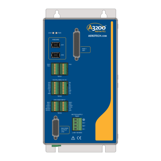
Introduction Chapter 1: Introduction Aerotech’s Ndrive FCL (Fast Linear Servo) network digital drive is a high-performance linear amplifier designed to eliminate the non-linearities common with PWM amplifiers. The drive provides deterministic behavior, auto-identification, and easy software setup. The Ndrive FCL’s high performance double precision floating point DSP controls the digital PID and current loops. -
Page 14: Figure 1-2: Functional Diagram
Introduction Ndrive FCL Hardware Manual The following block diagram shows a connection summary (refer to Chapter 2 and Chapter 3 for more detailed connection information). Figure 1-2: Functional Diagram Chapter 1 www.aerotech.com... -
Page 15: Electrical Specifications
Ndrive FCL Hardware Manual Introduction 1.1. Electrical Specifications The electrical specifications for the Ndrive FCL are listed below. Table 1-2: Electrical Specifications Description Ndrive FCL Input Voltage ±40 VDC (max) Motor Supply Input Current (continuous) 10 A Input Voltage 85-240 VAC Input Frequency... -
Page 16: Mechanical Design
Introduction Ndrive FCL Hardware Manual 1.2. Mechanical Design The following figure shows the Ndrive FCL package dimension as well as the typical mounting orientation. Refer to Section 2.3. for FireWire interconnection cable options. Table 1-3: Unit Weight Weight 2.9 kg [6.4 lb]... -
Page 17: Environmental Specifications
Decreasing linearly to 50% relative humidity at 40°C. Non condensing. Operating: 0 m to 2,000 m (0 ft to 6,562 ft) above sea level Altitude Contact Aerotech if your specific application involves use above 2,000 m or below sea level. Pollution Pollution degree 2 (normally only non-conductive pollution). -
Page 18: Drive And Software Compatibility
Introduction Ndrive FCL Hardware Manual 1.4. Drive and Software Compatibility The following table lists the available drives and which version of the software first supported the drive. Drives that list a specific version number in the Last Software Version column will not be supported after the listed version. -
Page 19: Chapter 2: Installation And Configuration
Ndrive FCL Hardware Manual Installation and Configuration Chapter 2: Installation and Configuration 2.1. Communication Channel Settings Use the Device Number switches to assign a communication channel number to the Ndrive FCL. If you are using multiple drives, each drive must be assigned a unique communication channel. Multiple drives are typically configured using sequential communication channels. -
Page 20: Power Connections
Installation and Configuration Ndrive FCL Hardware Manual 2.2. Power Connections The Ndrive FCL has two input power connectors; one for control power (AC) and a second for motor power (DC). For a complete list of electrical specifications, refer to Section 1.1. Electrical Specifications. -
Page 21: Motor Supply Connections (Tb201)
Ndrive FCL Hardware Manual Installation and Configuration 2.2.2. Motor Supply Connections (TB201) N O T E : This product requires two power supply connections. The Motor Supply and Control Supply must both be connected for proper operation. Motor power is applied to the Ndrive FCL at the four terminals of the Motor Supply connector (TB201). The DC+ and DC- inputs are internally fused. -
Page 22: External Power Supply Options
Installation and Configuration Ndrive FCL Hardware Manual 2.2.3. External Power Supply Options The Ndrive FCL requires a bipolar power supply for the motor supply connector TB201. A TM3 can be used to power up to 4 drives as shown in Figure 2-3. -
Page 23: Figure 2-4: Third Party Power Supply Connection
Ndrive FCL Hardware Manual Installation and Configuration Figure 2-4: Third Party Power Supply Connection www.aerotech.com Chapter 2... -
Page 24: Minimizing Conducted Radiated And System Noise
Installation and Configuration Ndrive FCL Hardware Manual 2.2.4. Minimizing Conducted Radiated and System Noise User connections to the product must be made using shielded cables with metal D-style connectors and back shells. The shield of the cables must be connected to the metal back shell in order for the product to conform to radiated emission standards. -
Page 25: Firewire Interface
Ndrive FCL Hardware Manual Installation and Configuration 2.3. FireWire Interface The FireWire bus is the high-speed communications connection to the Ndrive FCL operating at 400 megabits per second. All command and configuration information is sent via the FireWire port. Table 2-6:... -
Page 26: Motor And Feedback Connections (J201)
Ndrive FCL Hardware Manual 2.4. Motor and Feedback Connections (J201) The Ndrive FCL is only capable of controlling a DC Brush motor. The Motor and Feedback connector (a 25-pin, D-style connector) has an analog encoder input, 5 volt encoder power, and motor connections. -
Page 27: Analog Encoder Inputs (J201)
Installation and Configuration 2.4.1. Analog Encoder Inputs (J201) The Ndrive FCL will accept an analog encoder input signal. The multiplication (interpolation) factor is determined by the EncoderMultiplicationFactor parameter. The gain, offset, and phase balance of the analog Sine and Cosine encoder input signals can be adjusted by controller parameters. -
Page 28: Position Synchronized Output (Pso) (Tb101)
Ndrive FCL Hardware Manual 2.5. Position Synchronized Output (PSO) (TB101) The Ndrive FCL includes a Position Synchronized Output (PSO) feature. The PSO can be programmed to generate an output synchronized to the feedback position and is typically used to fire a laser or sequence an external device. Trigger signals may be derived from a feedback channel or a software trigger. -
Page 29: Encoder Input (Tb103 A/B)
TB103A/B. The encoder interfaces accept an RS-422 differential line driver. The auxiliary encoder input channels cannot be used for closing the position loop. They are intended to be used with the Infinite Field of View and the Marking on the Fly functionality of the Ndrive FCL. Table 2-15:... -
Page 30: Figure 2-5: Encoder Connections (Tb103 A/B)
Installation and Configuration Ndrive FCL Hardware Manual Figure 2-5: Encoder Connections (TB103 A/B) Chapter 2 www.aerotech.com... -
Page 31: Emergency Stop Sense Input
Ndrive FCL Hardware Manual Installation and Configuration 2.6.1. Emergency Stop Sense Input The ESTOP sense input is used to monitor the state of an external safety circuit only. This state is indicated by the software and may be used to facilitate system restart. This ESTOP sense input is not intended to be a complete safety system. -
Page 32: Encoder Output (J103)
Installation and Configuration Ndrive FCL Hardware Manual 2.7. Encoder Output (J103) The Encoder Output interface is used to echo the encoder signals from both axes. Table 2-22: Encoder Output Connector Pinout (J103) Description In/Out/Bi Connector SIN- Output Reserved COS- Output... -
Page 33: Figure 2-8: Pso External Sync Input
Ndrive FCL Hardware Manual Installation and Configuration Table 2-24: PSO External Sync Specifications Specification Value Voltage 3.3 VDC Frequency 25 MHz Maximum On Time 20 ns Minimum Figure 2-8: PSO External Sync Input www.aerotech.com Chapter 2... -
Page 34: Digital And Analog I/O
Installation and Configuration Ndrive FCL Hardware Manual 2.8. Digital and Analog I/O This connector has four digital, optically-isolated outputs, four digital, optically-isolated inputs, one differential analog input, and two analog outputs. Table 2-25: Digital Outputs and Differential Analog Inputs Pinout (TB102 A) -
Page 35: Digital Inputs (Tb102 B)
Ndrive FCL Hardware Manual Installation and Configuration 2.8.1. Digital Inputs (TB102 B) The digital inputs are opto-isolated and may be connected to current sourcing or current sinking devices, as shown in Figure 2-9 Figure 2-10. These inputs are designed to connect to other ground-referenced circuits and are not intended for high-voltage isolation. -
Page 36: Figure 2-9: Inputs Connected To A Current Sourcing Device
Installation and Configuration Ndrive FCL Hardware Manual Figure 2-9: Inputs Connected to a Current Sourcing Device Figure 2-10: Inputs Connected to a Current Sinking Device Chapter 2 www.aerotech.com... -
Page 37: Digital Outputs (Tb102 A)
Ndrive FCL Hardware Manual Installation and Configuration 2.8.2. Digital Outputs (TB102 A) The digital outputs are optically-isolated and may be connected in sourcing or sinking configurations. The digital outputs are designed to connect to other ground referenced circuits and are not intended to provide high-voltage isolation. -
Page 38: Figure 2-11: Outputs Connected In Current Sourcing Mode
Installation and Configuration Ndrive FCL Hardware Manual Figure 2-11: Outputs Connected in Current Sourcing Mode Figure 2-12: Outputs Connected in Current Sinking Mode Chapter 2 www.aerotech.com... -
Page 39: Differential Analog Input
Ndrive FCL Hardware Manual Installation and Configuration 2.8.3. Differential Analog Input To interface to a single-ended (non-differential) voltage source, connect the signal common of the source to the negative input and the analog source signal to the positive input. A floating signal source should be... -
Page 40: Analog Outputs (Tb102 B)
Installation and Configuration Ndrive FCL Hardware Manual 2.8.4. Analog Outputs (TB102 B) The analog output is set to zero when power is first applied to the system or during a system reset. Table 2-34: Analog Output Pins on the TB102 B Connector... -
Page 41: Laser Output Polarity
Ndrive FCL Hardware Manual Installation and Configuration 2.9. Laser Output Polarity The Laser Output Polarity switches are reserved for future use. www.aerotech.com Chapter 2... -
Page 42: Pc Configuration And Operation Information
Installation and Configuration Ndrive FCL Hardware Manual 2.10. PC Configuration and Operation Information For additional information about Ndrive FCL and PC configuration, hardware requirements, programming, utilities and system operation refer to the A3200 Help file. Chapter 2 www.aerotech.com... -
Page 43: Chapter 3: Maintenance
Ndrive FCL Hardware Manual Maintenance Chapter 3: Maintenance D A N G E R : Always disconnect the Mains power connection before opening the Ndrive FCL chassis. D A N G E R : Before performing any tests, be aware of lethal voltages inside the controller and at the input and output power connections. -
Page 44: Preventative Maintenance
Maintenance Ndrive FCL Hardware Manual 3.1. Preventative Maintenance The Ndrive FCL and external wiring should be inspected monthly. Inspections may be required at more frequent intervals, depending on the environment and use of the system. D A N G E R : Always disconnect the Mains power connection before opening the Ndrive FCL chassis. -
Page 45: Board Assembly
Ndrive FCL Hardware Manual Maintenance 3.2. Board Assembly D A N G E R : Always disconnect the Mains power connection before opening the Ndrive FCL chassis. Figure 3-1: Control Board Assembly Table 3-3: Control Board Fuse Specifications Fuse Description Size... -
Page 46: Figure 3-2: Power Board Assembly
Maintenance Ndrive FCL Hardware Manual D A N G E R : Always disconnect the Mains power connection before opening the Ndrive FCL chassis. Figure 3-2: Power Board Assembly Table 3-4: Power Board Fuses Fuse Description Size Aerotech P/N Manufacturer's P/N Motor Bus Supply 10 A S.B. -
Page 47: Appendix A: Warranty And Field Service
Aerotech makes no warranty that its products are fit for the use or purpose to which they may be put by the buyer, whether or not such use or purpose has been disclosed to Aerotech in specifications or drawings previously or subsequently provided, or whether or not Aerotech’s... - Page 48 Aerotech's approval. On-site Warranty Repair If an Aerotech product cannot be made functional by telephone assistance or by sending and having the customer install replacement parts, and cannot be returned to the Aerotech service center for repair, and if Aerotech determines the problem could be warranty-related, then the following policy applies:...
-
Page 49: Appendix B: Revision History
Ndrive FCL Hardware Manual Revision History Appendix B: Revision History Revision Description Added a new table: 1.02.00 Table 2-24 Updates have been made to: 1.01.00 EU Declaration of Conformity 1.00.00 New Manual www.aerotech.com Appendix B... - Page 50 Revision History Ndrive FCL Hardware Manual This page intentionally left blank. Appendix B www.aerotech.com...
-
Page 51: Index
Ndrive FCL Hardware Manual Index Index FireWire Card Part Numbers FireWire Interface 2014/35/EU FireWire Repeaters Functional Diagram Altitude Ambient Temperature Global Technical Support Analog Encoder Inputs Analog Encoder Specifications Humidity Check chassis for loose or damaged parts / Inputs Connected to a Current Sinking Device... - Page 52 Index Ndrive FCL Hardware Manual PSO External Sync Specifications PSO Output Sources Quick Installation Guide Quick Start Connections Revision History Standard Features Support TB103 TB104 TB109 TB201 Technical Support unit weight Index www.aerotech.com...
Need help?
Do you have a question about the Ndrive FCL and is the answer not in the manual?
Questions and answers