Table of Contents
Advertisement
Quick Links
Advertisement
Table of Contents

Related Manuals for Aerotech Automation1 XA4


Summary of Contents for Aerotech Automation1 XA4
-
Page 1: Automation1 Ixa4 And Xa4 Pwm Digital Drives
Automation1 iXA4 and XA4 PWM Digital Drives HARDWARE MANUAL Revision 1.03... - Page 2 This manual contains proprietary information and may not be reproduced, disclosed, or used in whole or in part without the express written permission of Aerotech, Inc. Product names mentioned herein are used for identification purposes only and may be trademarks of their respective companies.
-
Page 3: Table Of Contents
2.3.5. Encoder Fault Input 2.3.6. End of Travel and Home Limit Inputs 2.3.6.1. End of Travel and Home Limit Phasing 2.3.7. Brake Outputs 2.4. Safe Torque Off Input (STO) 2.4.1. STO Standards 2.4.2. STO Functional Description 2.4.3. STO Startup Validation Testing www.aerotech.com... - Page 4 3.5. Auxiliary Encoder Interface [-EB1/-EB2] 3.5.1. Square Wave Encoder (Auxiliary)[-EB1/-EB2] Chapter 4: Cables and Accessories 4.1. Joystick Interface 4.2. Handwheel Interface Chapter 5: Maintenance 5.1. Preventative Maintenance 5.2. Fuse Specifications Appendix A: Warranty and Field Service Appendix B: Revision History Index www.aerotech.com...
-
Page 5: List Of Figures
End of Travel and Home Limit Input Schematic (Feedback Connector) Figure 2-36: End of Travel and Home Limit Input Diagnostic Display Figure 2-37: Brake Connected to the 25-Pin Feedback Connector (Typical) Figure 2-38: Typical STO Configuration Figure 2-39: STO Timing Figure 2-40: PSO Interface Figure 2-41: High-Speed Inputs www.aerotech.com... - Page 6 Analog Input Typical Connection Figure 3-10: Square Wave Encoder Interface (Auxiliary) Figure 3-1: Two Axis Joystick Interface (to the -EB2 I/O Board) Figure 3-2: Handwheel Interconnection to the -EB2 I/O Board Figure 4-1: Fuse Locations on the iXA4 Control Board www.aerotech.com...
-
Page 7: List Of Tables
Table 2-16: Wire Colors for Aerotech-Supplied Brushless Motor Cables Table 2-17: Hall Signal Diagnostics Table 2-18: Wire Colors for Aerotech-Supplied DC Brush Motor Cables Table 2-19: Wire Colors for Aerotech-Supplied Stepper Motor Cables Table 2-20: Feedback Connector Pinout Table 2-21:... - Page 8 Auxiliary Encoder Connector Pinout [-EB2] Table 3-24: Analog Inputs Mating Connector Ratings [-EB2] Table 3-25: Square Wave Encoder Specifications Table 3-1: Standard Interconnection Cables Table 4-1: LED Description Table 4-2: Troubleshooting Table 4-3: Preventative Maintenance Table 4-4: Control Board Fuse Specifications www.aerotech.com...
-
Page 9: Eu Declaration Of Conformity
Hardware Manual iXA4/XA4 EU Declaration of Conformity Manufacturer Aerotech, Inc. Address 101 Zeta Drive Pittsburgh, PA 15238-2811 Product iXA4/XA4 Model/Types This is to certify that the aforementioned product is in accordance with the applicable requirements of the following directive(s): 2014/30/EU... -
Page 10: Ukca Declaration Of Conformity
Hardware Manual UKCA Declaration of Conformity Manufacturer Aerotech, Inc. Address 101 Zeta Drive Pittsburgh, PA 15238-2811 Product iXA4/XA4 Model/Types To which this declaration relates, meets the essential health and safety requirements and is in conformity with the relevant UK Legislation listed below:... -
Page 11: Safety Procedures And Warnings
To find the newest information about this product, refer to www.aerotech.com. If you do not understand the information in this manual, contact Aerotech Global Technical Support. IMPORTANT: This product has been designed for light industrial manufacturing or laboratory environments. - Page 12 2. Do not use the cables or the connectors to lift or move this product. 3. Use this product only in environments and operating conditions that are approved in this manual. 4. Only trained operators should operate this equipment. www.aerotech.com...
-
Page 13: Handling And Storage
Store the drive in the original shipping container. If the original packaging included ESD protective packaging, make sure to store the drive in it. The storage location must be dry, free of dust, free of vibrations, and flat. Refer to Section 1.6. Environmental Specifications. www.aerotech.com... -
Page 14: Installation Overview
With -EB1/-EB2: Connect additional I/O as required by your application. Chapter 3 Connect the Safe Torque Off (STO). Section 2.4. Connect the power supply to the Control Supply connector. Section 2.1.1. Connect the motor power to the Motor Supply connector. Section 2.1.2. www.aerotech.com... - Page 15 With -EB1/-EB2: Connect additional I/O as required by your application. Chapter 3 Connect the Safe Torque Off (STO). Section 2.4. Connect the power supply to the Control Supply connector. Section 2.1.1. Connect the motor power to the Motor Supply connector. Section 2.1.2. www.aerotech.com...
- Page 16 Hardware Manual This page intentionally left blank. www.aerotech.com...
-
Page 17: Chapter 1: Ixa4/Xa4 Overview
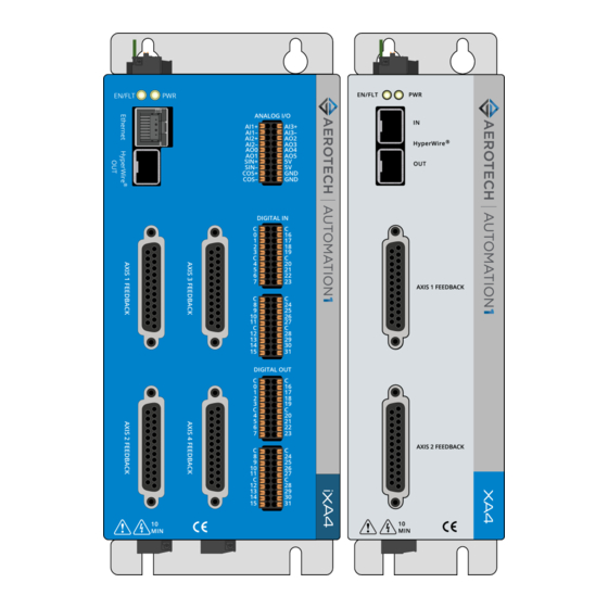
Torque Off (STO) inputs and optional Position Synchronized Output (PSO) outputs. And both drives are offered with an optional encoder interpolation feature (-MX1), dedicated analog and high-speed digital inputs, and separate power connections for motor and control supply voltages. Figure 1-1: iXA4 Digital Drive-Based Controller Labeled www.aerotech.com... -
Page 18: Figure 1-2: Xa4 Digital Drive Labeled
Hardware Manual Figure 1-2: XA4 Digital Drive Labeled www.aerotech.com... -
Page 19: Feature Summary
Refer to the online help for more information. Multi-Axis PSO Tracking: To track multiple axes... with Aerotech drives, use the Sync Ports (Section 2.8.) with non-Aerotech drives and square wave encoder signals, use the Auxiliary Encoder connector (Section 3.5.) or use the Primary Feedback connector (Section 2.3.) -
Page 20: Ordering Options
Three-axis Part-Speed PSO firing, which uses the PSO firing circuit based off of the -PSO6 commanded vector velocity of 3 or more axes (includes One-Axis PSO). Industrial Ethernet (iXA4 only) (Section 2.9.) -IE0 No industrial ethernet ports -IE1 Includes industrial ethernet ports www.aerotech.com... -
Page 21: Functional Block Diagram
Hardware Manual iXA4/XA4 1.3. Functional Block Diagram The block diagram that follows shows a summary of the connector signals. Figure 1-3: Functional Diagram www.aerotech.com... -
Page 22: Electrical Specifications
-20 Peak Voltage Option: 1200 W -10 Peak Voltage Option: 600 W (5) These values are based on using the maximum motor supply input voltage. (6) The drive can achieve the peak output current for each axis with all axes running. www.aerotech.com... -
Page 23: Table 1-4: Electrical Specifications (-Dc Option)
Remplacer toutes les parties endommagées. Si un grillage de l'élément de courant d'un relais de surcharge se produit, vous devez remplacer le relais de surcharge dans son ensemble. www.aerotech.com... -
Page 24: System Power Requirements
To achieve the maximum 17.5 days of real-time clock operation in the absence of the control supply, the capacitor must be charged for 36 minutes. If the capacitor is not fully charged when the control supply is lost, the real-time clock will not last the entire 17.5 days on backup capacitor power. www.aerotech.com... -
Page 25: Mechanical Specifications
~25 mm Minimum Clearance Connectors ~100 mm Operating Temperature Refer to Section 1.6. Environmental Specifications Drive IP Rating IP20 Mounting Panel Thickness (Recommended) 2.5 - 3.5 mm (.10 - .125 in) UL Enclosure Type Rating of Drive Open Type www.aerotech.com... -
Page 26: Dimensions
Hardware Manual 1.5.2. Dimensions IMPORTANT: iXA4 and XA4 with -AX1/-AX2 and -EB0 options have the same dimensions. iXA4-AX2-EB0 is shown. Figure 1-4: Dimensions (Two Axis iXA4) www.aerotech.com... -
Page 27: Figure 1-5: Dimensions (Two Axis Ixa4 With Expansion I/O Board)
Hardware Manual iXA4/XA4 IMPORTANT: iXA4 and XA4 with -AX1/-AX2 and -EB1/-EB2 options have the same dimensions. iXA4-AX2-EB2 is shown. Figure 1-5: Dimensions (Two Axis iXA4 with Expansion I/O Board) www.aerotech.com... -
Page 28: Figure 1-6: Dimensions (Four Axis Ixa4)
Hardware Manual IMPORTANT: iXA4 and XA4 with -AX4 and -EB0 options have the same dimensions. iXA4- AX4 is shown. Figure 1-6: Dimensions (Four Axis iXA4) www.aerotech.com... -
Page 29: Figure 1-7: Dimensions (Four Axis Ixa4 With I/O Expansion Board)
Hardware Manual iXA4/XA4 IMPORTANT: iXA4 and XA4 with -AX4 and -EB1/-EB2 options have the same dimensions. iXA4-AX4-EB2 is shown. Figure 1-7: Dimensions (Four Axis iXA4 with I/O Expansion Board) www.aerotech.com... -
Page 30: Environmental Specifications
Last Software Version column, drives that show a specific version number are not supported after that version. Table 1-7: Drive and Software Compatibility Drive Type Options First Software Version Last Software Version -AC; -AX1; -AX2; -EB0 2.7.0 Current iXA4/XA4 -DC; -AX4; -EB1; -EB2 2.8.0 Current www.aerotech.com... -
Page 31: Chapter 2: Installation And Configuration
Control Power Common Input Protective Ground Table 2-2: Control Supply Mating Connector Ratings Specification Description Type 3-Pin Terminal Block Aerotech: ECK02456 Part Numbers Phoenix: 1839610 One conductor, stranded with ferrule 18...22 AWG (0.25...0.75 mm and plastic sleeve Conductor Cross Two conductors (same cross-section),... -
Page 32: Motor Supply Connector
If your drive has the -DC Motor Supply option, refer to Section 2.1.2.2. If you have a combination of -AC and -DC Motor Supply option drives, Aerotech recommends that you key the Motor Supply connector and mating connectors. Refer to Section 2.1.2.3. -
Page 33: Motor Supply Connector (-Ac Option)
/ 14 AWG min conductor size Table 2-4: Motor Supply Mating Connector Ratings Specification Description Type 3-Pin Terminal Block Aerotech: ECK02388 Part Numbers Phoenix: 1756272 One conductor, stranded with ferrule 14...22 AWG (0.25...2.5 mm and plastic sleeve Conductor Cross Two conductors (same cross-section),... -
Page 34: Motor Supply Connector (-Dc Option)
/ 18 AWG min conductor size Table 2-6: Motor Supply Mating Connector Ratings Specification Description Type 3-Pin Terminal Block Aerotech: ECK02388 Part Numbers Phoenix: 1756272 One conductor, stranded with ferrule 14...22 AWG (0.25...2.5 mm and plastic sleeve Conductor Cross Two conductors (same cross-section),... -
Page 35: Motor Supply Keying
2.1.2.3. Motor Supply Keying If you have a combination of -AC and -DC Option drives, Aerotech recommends that you key the Motor Supply Connector and mating connectors. You must use keys on both the drive and any mating cables in order for the keys to be effective. -
Page 36: Figure 2-5: Recommended Keying For -Ac Options
Hardware Manual Table 2-8: Recommended Keying for -AC Options (Drive Connector) Action Do not key Do not key Table 2-9: Recommended Keying for -AC Options (AC Supply Cables) Action Do not key Figure 2-5: Recommended Keying for -AC Options www.aerotech.com... -
Page 37: Figure 2-6: Recommended Keying For -Dc Options
Hardware Manual iXA4/XA4 Table 2-10: Recommended Keying for -DC Options (Drive Connector) Action Do not key Table 2-11: Recommended Keying for -DC Options (DC Supply Cables) Action Do not key Do not key Figure 2-6: Recommended Keying for -DC Options www.aerotech.com... -
Page 38: Transformer Options (-Ac Option)
Generate 56 VAC from 115 VAC or 230 VAC input source voltage. When TV0.3-56 rectified by the drive, it produces an 80 VDC power bus. 1.5 kVA, 2.5 kVA, or 5 kVA isolation transformer; 115/230 VAC input; 28, 43, 56, TV1.5, TV2.5, or TV5 70, 115 VAC output www.aerotech.com... -
Page 39: Figure 2-7: Tv0.3-28-56-St Transformer Motor Power Wiring (40 Vdc Bus) [-Ac Option]
Hardware Manual iXA4/XA4 Figure 2-7: TV0.3-28-56-ST Transformer Motor Power Wiring (40 VDC Bus) [-AC Option] www.aerotech.com... -
Page 40: Figure 2-8: Tv0.3-28-56-St Transformer Motor Power Wiring (80 Vdc Bus) [-Ac Option]
Hardware Manual Figure 2-8: TV0.3-28-56-ST Transformer Motor Power Wiring (80 VDC Bus) [-AC Option] www.aerotech.com... -
Page 41: Figure 2-9: Tv0.3-28-56-St Transformer Motor Power Wiring (160 Vdc Bus) [-Ac Option]
Hardware Manual iXA4/XA4 Figure 2-9: TV0.3-28-56-ST Transformer Motor Power Wiring (160 VDC Bus) [-AC Option] www.aerotech.com... -
Page 42: Figure 2-10: Tv0.3-28 Transformer Motor Power Wiring (40 Vdc Bus) [-Ac Option]
Hardware Manual Figure 2-10: TV0.3-28 Transformer Motor Power Wiring (40 VDC Bus) [-AC Option] www.aerotech.com... -
Page 43: Figure 2-11: Tv0.3-56 Transformer Motor Power Wiring (80 Vdc Bus) [-Ac Option]
Hardware Manual iXA4/XA4 Figure 2-11: TV0.3-56 Transformer Motor Power Wiring (80 VDC Bus) [-AC Option] www.aerotech.com... -
Page 44: Figure 2-12: Tm3/Tm5 Transformer Motor Power Wiring [-Ac Option]
Hardware Manual Figure 2-12: TM3/TM5 Transformer Motor Power Wiring [-AC Option] www.aerotech.com... -
Page 45: Minimizing Noise For Emc/Ce Compliance
4. Add a ferrite core to the motor phase and ground wires close to the drive. Wrap all four wires around the ferrite core once. Remove ferrite beads from Aerotech supplied cables if installed. [Ferrite core: Aerotech PN ECZ02349, Fair-rite PN 2646626402] 5. -
Page 46: Motor Power Output Connectors
Motor Phase B Output Motor Phase C Output Table 2-15: Motor Power Output Mating Connector Ratings Specification Description Type 4-Pin Terminal Block Aerotech: ECK02593 Part Numbers Phoenix: 1756298 One conductor, stranded with ferrule and 14...22 AWG (0.25...2.5 mm plastic sleeve Conductor Cross Section Two conductors (same cross-section), 16...20 AWG (0.5...1.5 mm... -
Page 47: Brushless Motor Connections
Black #3 Violet & Blue (1) Wire Color Set #1 is the wire set typically used by Aerotech. (2) “&” indicates two wires (Red & Orange); “ / ” indicates a single wire (Green/White). Brushless motors are commutated electronically by the controller. The use of Hall effect devices for commutation is recommended. -
Page 48: Brushless Motor Powered Motor And Feedback Phasing
Observe the state of the encoder and Hall-effect device signals in the Diagnostics section of the Status Utility. Table 2-17: Hall Signal Diagnostics Hall-Signal Status Definition 0 V or logic low 5 V or logic high Figure 2-14: Positive Motor Direction Figure 2-15: Encoder and Hall Signal Diagnostics www.aerotech.com... -
Page 49: Brushless Motor Unpowered Motor And Feedback Phasing
With the designations of the motor and Hall leads of a third party motor determined, the motor can now be connected to an Aerotech system. Connect motor lead A to motor connector A, motor lead B to motor connector B, and motor lead C to motor connector C. Hall leads should also be connected to their respective feedback connector pins (Hall A lead to the Hall A feedback pin, Hall B to Hall B, and Hall C to Hall C). -
Page 50: Dc Brush Motor Connections
Yellow & Blue Black Yellow & Blue (1) Wire Color Set #1 is the typical wire set used by Aerotech. (2) “&” (Red & Orange) indicates two wires; “ / ” (Green/White) indicates a single wire. 2.2.2.1. DC Brush Motor Phasing A properly phased motor means that the positive motor lead should be connected to the ØA motor terminal... -
Page 51: Stepper Motor Connections
Yellow White White & Red (1) Wire Color Set #1 is the typical wire set used by Aerotech. (2) “&” (Red & Orange) indicates two wires; “ / ” (Green/White) indicates a single wire. 2.2.3.1. Stepper Motor Phasing A stepper motor can be run with or without an encoder. -
Page 52: Three Phase Stepper Motor Connections
2-23). If the motor moves in a counterclockwise direction, reverse the motor leads and re-run the command. After the motor has been phased, if you want to change the direction of positive motion, use the ReverseMotionDirection parameter. Figure 2-23: Positive Motor Direction www.aerotech.com... -
Page 53: Feedback Connectors
Connector Analog Input + Input Motor Over Temperature Thermistor Input +5V Power Output Plug and Play Serial Data (for Aerotech stages only) Bidirectional Hall-Effect Sensor B (brushless motors only) Input Encoder Marker Reference Pulse - Input Absolute Encoder Clock -... -
Page 54: Primary Encoder Inputs
Bidirectional Encoder Cosine + Input Encoder Cosine - Input +5V Power Output Encoder Sine + Input Encoder Sine - Input Absolute Encoder Data+ Bidirectional Signal Common Output Signal Common Output (1) The maximum combined current output is 500 mA. www.aerotech.com... -
Page 55: Square Wave Encoder (Primary)
Use twisted-pair wiring for the highest performance and noise immunity. Table 2-24: Square Wave Encoder Specifications Specification Value Encoder Frequency 10 MHz maximum (25 ns minimum edge separation) x4 Quadrature Decoding 40 million counts/sec Figure 2-24: Square Wave Encoder Schematic (Feedback Connector) www.aerotech.com... -
Page 56: Absolute Encoder (Primary)
Refer to the Help file for information on how to set up your EnDat, BiSS, or SSI absolute encoder parameters. Table 2-25: Absolute Encoder Specifications Specification Value Sampling Frequency 10 kHz Maximum Reading Speed Refer to your encoder data sheet. Figure 2-25: Absolute Encoder Schematic (Feedback Connector) www.aerotech.com... -
Page 57: Sine Wave Encoder (Primary) [-Mx1 Option]
Input Frequency (max) 450 kHz Input Amplitude 0.6 to 1.75 Vpk-pk Interpolation Factor (max) 4,096 Input Common Mode 1.5 to 3.5 VDC (1) Measured as SIN(+) - SIN(-) or COS(+) - COS(-) Figure 2-26: Sine Wave Encoder Phasing Reference Diagram www.aerotech.com... -
Page 58: Figure 2-27: Sine Wave Encoder Schematic (Feedback Connector)
Hardware Manual Figure 2-27: Sine Wave Encoder Schematic (Feedback Connector) www.aerotech.com... -
Page 59: Encoder Phasing
Figure 2-28: Encoder Phasing Reference Diagram (Standard) IMPORTANT: Encoder manufacturers may refer to the encoder signals as A, B, and Z. The proper phase relationship between signals is shown in Figure 2-28. Figure 2-29: Position Feedback in the Diagnostic Display www.aerotech.com... -
Page 60: Hall-Effect Inputs
Hall-Effect Sensor A (brushless motors only) Input Hall-Effect Sensor C (brushless motors only) Input +5V Power Output Signal Common Output Signal Common Output (1) The maximum combined current output is 500 mA. Figure 2-30: Hall-Effect Inputs Schematic (Feedback Connector) www.aerotech.com... -
Page 61: Analog Inputs (Differential)
1. Signals outside of this range may damage the input Table 2-29: Analog Input Pins on the Feedback Connector Pin # Description In/Out/Bi Analog Input + Input Analog Input - Input Signal Common Output Signal Common Output Figure 2-31: Analog Inputs Schematic www.aerotech.com... -
Page 62: Thermistor Input
1.385 kΩ. The circuit includes a 1 kΩ internal pull-up resistor which corresponds to a trip voltage of +1.5 V. Table 2-30: Thermistor Input Pin on the Feedback Connector Pin # Description In/Out/Bi Motor Over Temperature Thermistor Input Figure 2-32: Thermistor Input Schematic (Feedback Connector) www.aerotech.com... -
Page 63: Encoder Fault Input
The nominal trip voltage of the encoder fault input is +1.5 V. Table 2-31: Encoder Fault Input Pin on the Feedback Connector Pin # Description In/Out/Bi Encoder Fault Input Input Figure 2-33: Encoder Fault Input Schematic (Feedback Connector) www.aerotech.com... -
Page 64: End Of Travel And Home Limit Inputs
Figure 2-34 shows the possible wiring configurations for normally-open and normally-closed switches and the parameter setting to use for each configuration. IMPORTANT: Use NPN-type normally-closed limit switches (Active High) to provide fail-safe behavior in the event of an open circuit. www.aerotech.com... -
Page 65: Figure 2-34: End Of Travel And Home Limit Input Connections
Hardware Manual iXA4/XA4 Figure 2-34: End of Travel and Home Limit Input Connections Figure 2-35: End of Travel and Home Limit Input Schematic (Feedback Connector) www.aerotech.com... -
Page 66: End Of Travel And Home Limit Phasing
CW and CCW limit functionality in the software using the EndOfTravelLimitSetup parameter. View the logic level of the EOT limit inputs in the Diagnostics display (shown in Figure 2-36). Figure 2-36: End of Travel and Home Limit Input Diagnostic Display www.aerotech.com... -
Page 67: Brake Outputs
Brake Output + Output Table 2-34: Brake Control Specifications Specification Value Maximum Voltage 24 VDC Maximum Current A varistor must be connected across the brake to minimize voltage transients. Figure 2-37: Brake Connected to the 25-Pin Feedback Connector (Typical) www.aerotech.com... -
Page 68: Safe Torque Off Input (Sto)
Output RETURN. Not for customer use. Table 2-36: STO Mating Connector Ratings Specification Description Type 5-Pin Terminal Block Aerotech: ECK02393 Part Numbers Phoenix: 1827622 One conductor, stranded with ferrule 18...22 AWG (0.25...0.75 mm and plastic sleeve Conductor Cross Two conductors (same cross-section),... -
Page 69: Figure 2-38: Typical Sto Configuration
WARNING: The drive does not check for short circuits on the external STO wiring. If this is not done by the external safety device, short circuits on the wiring must be excluded. Refer to EN ISO 13849-2. For Category 4 systems, the exclusion of short circuits is mandatory. Figure 2-38: Typical STO Configuration www.aerotech.com... -
Page 70: Sto Standards
Interval for manual STO test: EN/IEC 61508 Once per year for SIL2/PL d/category 3 Once per three months for SIL3/PL e/category 3 Once per day for SIL3/PL e/category 4 SIL3 EN/IEC 61508 PFH < 3 FIT SFF > 99% www.aerotech.com... -
Page 71: Sto Functional Description
ESTOP signal becomes active. Use the EmergencyStopFaultInput parameter to configure a digital input as an ESTOP input. The STO feature can only be used with AC or stepper motor types. It is not certified to prevent hazardous motion when using DC brush motor types. www.aerotech.com... -
Page 72: Sto Startup Validation Testing
(24 V). An “ON” indicates that the voltage source has been removed from the input (open circuit or 0 V), and that the STO channel is in the safe state. DANGER: The STO circuit does not remove lethal voltage from the motor terminals. AC mains power must be removed before servicing. www.aerotech.com... -
Page 73: Sto Diagnostics
STO inputs before the STO Delay Time, an STO hardware shutdown will not occur but a software stop may, depending on the width of the STO pulse. The controller will ignore STO active pulses shorter in length than the STOPulseFilter parameter setting. www.aerotech.com... -
Page 74: Position Synchronized Output (Pso)
25 ns [Fire event to output change] Table 2-44: PSO/High-Speed Input Connector Pin# Description In/Out/Bi Connector Output Ground Output High-Speed Input 0+ Input High-Speed Input 0- Input High-Speed Input 1+ Input High-Speed Input 1- Input Figure 2-40: PSO Interface www.aerotech.com... -
Page 75: High-Speed Inputs
10 mA Input Device HCPL-0630 Delay 50 nsec Table 2-46: PSO/High-Speed Input Connector Pin# Description In/Out/Bi Connector Output Ground Output High-Speed Input 0+ Input High-Speed Input 0- Input High-Speed Input 1+ Input High-Speed Input 1- Input Figure 2-41: High-Speed Inputs www.aerotech.com... -
Page 76: Hyperwire Interface
HyperWire Cable Part Numbers Part Number Description HYPERWIRE-AO10-5 HyperWire cable, active optical, 0.5 m HYPERWIRE-AO10-10 HyperWire cable, active optical, 1.0 m HYPERWIRE-AO10-30 HyperWire cable, active optical, 3.0 m HYPERWIRE-AO10-50 HyperWire cable, active optical, 5.0 m HYPERWIRE-AO10-200 HyperWire cable, active optical, 20.0 m www.aerotech.com... -
Page 77: Sync Port (-Ax4, -Eb1, Or -Eb2 Options Only)
The controller is equipped with 100BASE-TX Industrial Ethernet ports. IMPORTANT: Industrial Ethernet is only available on the iXA4. For the location of the ports, refer to Figure 1-1. For cable part numbers, refer to Table 3-1. For more information, refer to the Help system. www.aerotech.com... -
Page 78: System Interconnection
Hardware Manual 2.10. System Interconnection Figure 2-42: iXA4-AC Drive-Based System Wiring Drawing (Best Practice) Figure 2-43: XA4-AC PC-Based System Wiring Drawing (Best Practice) www.aerotech.com... -
Page 79: Figure 2-44: Ixa4-Dc Drive-Based System Wiring Drawing (Best Practice)
Hardware Manual iXA4/XA4 Figure 2-44: iXA4-DC Drive-Based System Wiring Drawing (Best Practice) Figure 2-45: XA4-DC PC-Based System Wiring Drawing (Best Practice) www.aerotech.com... -
Page 80: Figure 2-46: Ixa4-Ac Recommended System Connections For A Drive-Based Controller
Hardware Manual Figure 2-46: iXA4-AC Recommended System Connections for a Drive-Based Controller www.aerotech.com... -
Page 81: Figure 2-47: Xa4-Ac Recommended System Connections For A Pc-Based Controller
Hardware Manual iXA4/XA4 Figure 2-47: XA4-AC Recommended System Connections for a PC-Based Controller www.aerotech.com... -
Page 82: Figure 2-48: Ixa4-Dc Recommended System Connections For A Drive-Based Controller
Hardware Manual Figure 2-48: iXA4-DC Recommended System Connections for a Drive-Based Controller www.aerotech.com... -
Page 83: Figure 2-49: Xa4-Dc Recommended System Connections For A Pc-Based Controller
Hardware Manual iXA4/XA4 Figure 2-49: XA4-DC Recommended System Connections for a PC-Based Controller www.aerotech.com... -
Page 84: Pc Configuration And Operation Information
Hardware Manual 2.11. PC Configuration and Operation Information For more information about hardware requirements, PC configuration, programming, system operation, and utilities, refer to the Help file. www.aerotech.com... -
Page 85: Chapter 3: -Eb1/-Eb2 Option Expansion Board
The -EB1 option board has 16 digital inputs, 16 digital outputs, 2 analog inputs, 2 analog outputs, and an auxiliary square-wave encoder input channel. The -EB2 option board has 32 digital inputs, 32 digital outputs, 3 analog inputs, 6 analog outputs, and an auxiliary square-wave encoder input channel. Figure 3-1: -EB1 and -EB2 I/O Option Board Connectors www.aerotech.com... -
Page 86: Digital Outputs [-Eb1/-Eb2]
24 V (26 V Maximum) Maximum Sink/Source Current 250 mA/output Output Saturation Voltage 0.9 V at maximum current Output Resistance 3.7 Ω Rise / Fall Time 250 µs (2K pull up to 24V) Reset State Output Off (High Impedance State) www.aerotech.com... -
Page 87: Table 3-2: Digital Output Connectors Pinout [-Eb1]
Output 14 (Optically-Isolated) Output 15 (Optically-Isolated) Table 3-3: Digital Output Mating Connector Ratings [-EB1] Specification Description Type 10-Pin Terminal Block Aerotech: ECK02750 Part Numbers Phoenix: 1821177 Solid or stranded 20...26 AWG (0.14...0.5 mm Conductor Stranded, with ferrule, without plastic Cross Section 22...24 AWG (0.25...0.34 mm... -
Page 88: Table 3-4: Digital Output Connectors Pinout [-Eb2]
Output 15 (Optically-Isolated) Output 31 (Optically-Isolated) Table 3-5: Digital Output Mating Connector Ratings [-EB2] Specification Description Type 20-Pin Terminal Block Aerotech: ECK02751 Part Numbers Phoenix: 1844659 Solid or stranded 20...26 AWG (0.14...0.5 mm Conductor Stranded, with ferrule, without plastic Cross Section 22...24 AWG (0.25...0.34 mm... -
Page 89: Figure 3-2: Digital Outputs Schematic [-Eb1/-Eb2]
Hardware Manual iXA4/XA4 Figure 3-2: Digital Outputs Schematic [-EB1/-EB2] www.aerotech.com... -
Page 90: Figure 3-3: Digital Outputs Connected In Current Sourcing Mode [-Eb1/-Eb2]
Hardware Manual Figure 3-3: Digital Outputs Connected in Current Sourcing Mode [-EB1/-EB2] Figure 3-4: Digital Outputs Connected in Current Sinking Mode [-EB1/-EB2] www.aerotech.com... -
Page 91: Digital Inputs [-Eb1/-Eb2]
Input 14 (Optically-Isolated) Input 15 (Optically-Isolated) Table 3-8: Digital Inputs Mating Connector Ratings [-EB1] Specification Description Type 10-Pin Terminal Block Aerotech: ECK02750 Part Numbers Phoenix: 1821177 Solid or stranded 20...26 AWG (0.14...0.5 mm Conductor Stranded, with ferrule, without plastic Cross Section 22...24 AWG (0.25...0.34 mm... -
Page 92: Table 3-9: Digital Input Connectors Pinout [-Eb2]
Input 15 (Optically-Isolated) Input 31 (Optically-Isolated) Table 3-10: Digital Input Mating Connector Ratings [-EB2] Specification Description Type 20-Pin Terminal Block Aerotech: ECK02751 Part Numbers Phoenix: 1844659 Solid or stranded 20...26 AWG (0.14...0.5 mm Conductor Stranded, with ferrule, without plastic Cross Section 22...24 AWG (0.25...0.34 mm... -
Page 93: Figure 3-5: Digital Inputs Schematic [-Eb1/-Eb2]
Hardware Manual iXA4/XA4 Figure 3-5: Digital Inputs Schematic [-EB1/-EB2] www.aerotech.com... -
Page 94: Figure 3-6: Digital Inputs Connected To Current Sourcing (Pnp) Devices [-Eb1/-Eb2]
IMPORTANT: Each bank of four inputs must be connected in an all sourcing or all sinking configuration. Figure 3-6: Digital Inputs Connected to Current Sourcing (PNP) Devices [-EB1/-EB2] Figure 3-7: Digital Inputs Connected to Current Sinking (NPN) Devices [-EB1/-EB2] www.aerotech.com... -
Page 95: Analog Outputs [-Eb1/-Eb2]
Auxiliary Encoder Cosine - Bidirectional Table 3-13: Analog Outputs Mating Connector Ratings [-EB1] Specification Description Type 10-Pin Terminal Block Aerotech: ECK02750 Part Numbers Phoenix: 1821177 Solid or stranded 20...26 AWG (0.14...0.5 mm Conductor Stranded, with ferrule, without plastic Cross Section 22...24 AWG (0.25...0.34 mm... -
Page 96: Figure 3-8: Analog Output Typical Connection
Aux Cosine - Ground Table 3-15: Analog Outputs Mating Connector Ratings [-EB2] Specification Description Type 20-Pin Terminal Block Aerotech: ECK02751 Part Numbers Phoenix: 1844659 Solid or stranded 20...26 AWG (0.14...0.5 mm Conductor Stranded, with ferrule, without plastic Cross Section 22...24 AWG (0.25...0.34 mm... -
Page 97: Analog Inputs [-Eb1/-Eb2]
Auxiliary Encoder Cosine - Bidirectional Table 3-18: Analog Inputs Mating Connector Ratings [-EB1] Specification Description Type 10-Pin Terminal Block Aerotech: ECK02750 Part Numbers Phoenix: 1821177 Solid or stranded 20...26 AWG (0.14...0.5 mm Conductor Stranded, with ferrule, without plastic Cross Section 22...24 AWG (0.25...0.34 mm... -
Page 98: Figure 3-9: Analog Input Typical Connection
Aux Cosine - Ground Table 3-20: Analog Inputs Mating Connector Ratings [-EB2] Specification Description Type 20-Pin Terminal Block Aerotech: ECK02751 Part Numbers Phoenix: 1844659 Solid or stranded 20...26 AWG (0.14...0.5 mm Conductor Stranded, with ferrule, without plastic Cross Section 22...24 AWG (0.25...0.34 mm... -
Page 99: Auxiliary Encoder Interface [-Eb1/-Eb2]
Auxiliary Encoder Cosine - Bidirectional Table 3-22: Analog Inputs Mating Connector Ratings [-EB1] Specification Description Type 10-Pin Terminal Block Aerotech: ECK02750 Part Numbers Phoenix: 1821177 Solid or stranded 20...26 AWG (0.14...0.5 mm Conductor Stranded, with ferrule, without plastic Cross Section 22...24 AWG (0.25...0.34 mm... -
Page 100: Table 3-23: Auxiliary Encoder Connector Pinout [-Eb2]
Aux Cosine - Ground Table 3-24: Analog Inputs Mating Connector Ratings [-EB2] Specification Description Type 20-Pin Terminal Block Aerotech: ECK02751 Part Numbers Phoenix: 1844659 Solid or stranded 20...26 AWG (0.14...0.5 mm Conductor Stranded, with ferrule, without plastic Cross Section 22...24 AWG (0.25...0.34 mm... -
Page 101: Square Wave Encoder (Auxiliary)[-Eb1/-Eb2]
IMPORTANT: -EB2 Aux Encoder connector includes 5 V and GND pins that you can use to power the auxiliary encoder. For -EB1, you should use the +5 V and GND pins that are accessible on the axis feedback connector(s). Figure 3-10: Square Wave Encoder Interface (Auxiliary) www.aerotech.com... - Page 102 Hardware Manual This page intentionally left blank. www.aerotech.com...
-
Page 103: Chapter 4: Cables And Accessories
Refer to Section 4.1. Joystick Interface Handwheel Refer to Section 4.2. Handwheel Interface (1) The "-xx" indicates length in decimeters. (2) iXA4 Only (3) Make sure that you are using a shielded USB-C cable that is designed for data transfer. www.aerotech.com... -
Page 104: Joystick Interface
Hardware Manual 4.1. Joystick Interface Aerotech Multi-Axis Joystick (NEMA12 (IP54) rated) is powered from 5 V and has a nominal 2.5 V output in the center detent position. Three buttons are used to select axis pairs and speed ranges. An optional interlock signal is used to indicate to the controller that the joystick is present. -
Page 105: Handwheel Interface
IMPORTANT: You can find instructions on how to enable the handwheel in the online Help file. Connect a handwheel to the Aux connector as shown in Figure 3-2. Figure 3-2: Handwheel Interconnection to the -EB2 I/O Board www.aerotech.com... - Page 106 Hardware Manual This page intentionally left blank. www.aerotech.com...
-
Page 107: Chapter 5: Maintenance
The light is configured to blink for setup. Table 4-2: Troubleshooting Symptom Possible Cause and Solution Make sure the power LED is illuminated (this indicates that power is present). No Communication Make sure that all communication cables (HyperWire, for example) are fully inserted in their ports. www.aerotech.com... -
Page 108: Preventative Maintenance
Internal contamination from the cleaning solution can cause corrosion and electrical short circuits. Do not clean the labels with a cleaning solution because it might remove the label information. www.aerotech.com... -
Page 109: Fuse Specifications
Hardware Manual iXA4/XA4 5.2. Fuse Specifications WARNING: Replace fuses only with the same type and value. Table 4-4: Control Board Fuse Specifications Aerotech Third Party SCCR Fuse Description Size Littelfuse F200 Control Power at +24 V Input 5 A S.B. - Page 110 Hardware Manual This page intentionally left blank. www.aerotech.com...
-
Page 111: Appendix A: Warranty And Field Service
Aerotech makes no warranty that its products are fit for the use or purpose to which they may be put by the buyer, whether or not such use or purpose has been disclosed to Aerotech in specifications or drawings previously or subsequently provided, or whether or not Aerotech’s... - Page 112 On-site Non-Warranty Repair If any Aerotech product cannot be made functional by telephone assistance or purchased replacement parts, and cannot be returned to the Aerotech service center for repair, then the following field service policy applies: Aerotech will provide an on-site Field Service Representative in a reasonable amount of time, provided that the customer issues a valid purchase order to Aerotech covering all transportation and subsistence costs and the prevailing labor cost, including travel time, necessary to complete the repair.
-
Page 113: Appendix B: Revision History
Revision Description Updated: Feature Summary (Section 1.1.) 1.03 Electrical Specifications (Section 1.4.) Table 4-1 (red power description) 1.02 Update to Section 1.4. Electrical Specifications Updated Section 2.1.1. Control Supply Connector 1.01 Added Section 2.10. System Interconnection 1.00 New Manual www.aerotech.com... - Page 114 Hardware Manual This page intentionally left blank. www.aerotech.com...
-
Page 115: Index
Check for fluids or electrically conductive material exposure 108 Analog Inputs [-EB1] Cleaning Analog Inputs Schematic Commands Analog Output Connector Pinout [-EB1] Sync Analog Output Connector Pinout [-EB2] Conducted and Radiated Emissions 9-10 Analog Output Specifications [-EB1] Conductors specifications Analog Output Typical Connection [-EB1] www.aerotech.com... - Page 116 Dimensions examining, dangerous fluids Dimensions (without -EB1) 26-29 examining, dangerous material Drawing number Drive and Software Compatibility Drive IP Rating IP20 Feedback Connector Absolute Encoder Brake Outputs Encoder Electrical Safety for Power Drive Systems 9-10 Encoder Fault Input www.aerotech.com...
- Page 117 Outputs Connected in Current Sourcing Mode [-EB1] IP20 Drive IP Rating Positive Motor Direction IP54 Compliant Enclosure Square Wave Encoder Schematic (Feedback Connector) 55 Stepper Motor Configuration STO Timing Thermistor Input Schematic Joystick Interface Three Phase Stepper Motor Configuration Typical STO Configuration www.aerotech.com...
- Page 118 Position Feedback in the Diagnostic Display Multi-Axis PSO Tracking with the Sync Port Position Synchronized Output (Aux I/O Connector) Positive Motor Direction Power Amplifier Bandwidth specification Power Requirements Nominal Motor Operating Voltages / Required AC Voltages Preventative Maintenance Primary Encoder (Feedback Connector) www.aerotech.com...
-
Page 119: Table 3-25: Square Wave Encoder Specifications
Three Phase Stepper Motor Connections (Motor Power High-Speed Inputs Output Connector) PSO (Aux I/O Connector) RS-422 Encoder (Feedback Connector) 55,101 Sine Wave Encoder (Feedback Connector) Transformer Options Square Wave Encoder (Feedback Connector) 55,101 Travel Limit Input (Feedback Connector) Unit Weight TV0.3-28 www.aerotech.com... - Page 120 TV0.3-56 Transformer (80 VDC Bus) Typical STO Configuration Unit Weight User Power Supply Output specification Warranty and Field Service Wire Colors for Aerotech-Supplied Brushless Motor Cables Wire Colors for Aerotech-Supplied DC Brush Motor Cables Wire Colors for Aerotech-Supplied Stepper Motor Cables www.aerotech.com...
Need help?
Do you have a question about the Automation1 XA4 and is the answer not in the manual?
Questions and answers