Sign In
Upload
Manuals
Brands
Eaton Manuals
Circuit breakers
Cutler-Hammer 50DHP-VR250U
Eaton Cutler-Hammer 50DHP-VR250U Manuals
Manuals and User Guides for Eaton Cutler-Hammer 50DHP-VR250U. We have
1
Eaton Cutler-Hammer 50DHP-VR250U manual available for free PDF download: Instructions For Installation, Operation And Maintenance
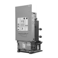
Eaton Cutler-Hammer 50DHP-VR250U Instructions For Installation, Operation And Maintenance (56 pages)
Vacuum Replacement Circuit Breakers for DHP Switchgear
Brand:
Eaton
| Category:
Circuit breakers
| Size: 4.83 MB
Table of Contents
Table of Contents
4
Section 1 Introduction
7
Available DHP-VR Breakers
7
Type DHP-VR Vaccum Circuit Breaker Availability and Interchangeability
7
Outline and Dimensions (Inches) Type DHP-VR Breakers (5 Kv, 250 MVA Rating)
8
Outline and Dimensions (Inches) Type DHP-VR Breakers (5 Kv, 350 MVA Rating)
9
Outline and Dimensions (Inches) Type DHP-VR Breakers (7.5 Kv and 15 Kv Ratings)
10
Section 2 Safe Practices
11
Section 3 Receiving, Handling and Storage
12
Receiving
12
Handling
12
Typical DHP-VR Tools and Accessories
12
Storage
13
DHP-VR Weights
13
Front External View of DHP-VR Breaker (5 Kv, 250 MVA Rating)
14
Rear External View of DHP-VR Breaker (5 Kv, 250 MVA Rating)
15
Front External View of DHP-VR Breaker (7.5 and 15 Kv, 500 and 750 MVA Ratings)
16
Rear External View of DHP-VR Breaker (7.5 and 15 Kv, 500 and 750 MVA Ratings)
17
Section 4 Installation
18
Initial Inspection and Operation
18
SURE CLOSE MECHANISM Adjustment
18
MOC Drive Spring
19
Drive Spring Adjusted for 0 to 1 MOC Switch
19
Drive Spring Adjustment Graphic
19
Checking Drive Spring for Proper Adjustment for One Installed Moc Switch
19
Drive Spring Shown Adjusted for 2 MOC Switches
20
4-6A Drive Spring Shown Adjusted for 3 MOC Switches
20
4-6B 5 Kv Drive Spring Adjusted for 3 MOC Switches
20
MOC Pantograph Adjustment
20
Mechanism Operated Cell (MOC) Switch Pantograph Adjustment
20
Manual Operation Check
21
Vacuum Interrupter Integrity
21
Insulation
21
Contact Erosion and Wipe
21
Primary Circuit Resistance
21
Nameplate
21
Snubber Adjustment
21
Electrical Operations Check
21
Snubber Adjustment
22
Positioning of 5 Kv DHP-VR Breaker
23
Positioning of 7.5 or 15 Kv DHP-VR Breaker
24
Final Engagement of 5 Kv Secondary Contact
24
Final Engagement of 7.5 or 15 Kv Secondary Contact
24
Lever Breaker into Cell
24
Levering 5 Kv Breaker to Connected Position
25
Levering 7.5 or 15 Kv Breaker to Connected Position
25
Removing Breaker from Cell
25
DHP-VR 5 Kv Interrupter Assembly
26
DHP-VR 7.5 or 15 Kv Interrupter Assembly
26
5-1.1 Vacuum Interrupter
27
5-1.2 Contact Erosion Indicator
27
5-1.3 "T" Cutout Loading Spring Indicator
27
5-1.4 Contact Wipe and Stroke
27
5-1.5 Phase Barriers
28
Section 5 Description and Operation
26
Interrupter Assembly
26
Stored Energy Mechanism
28
5-2.1 Operation of Stored Energy Mechanism
28
5-2.2 Charging
28
5-2.3 Closing Operation
28
DHP-VR 5 Kv Design - Front Faceplate Removed
29
DHP-VR 7.5 or 15 Kv Design - Front Faceplate Removed
30
Closing Cam and Trip Linkage
31
Charging Schematic
32
5-2.4 Tripping Operation
33
5-2.5 Trip Free Operation
33
Control Scheme
33
5-3.1 Timing
33
5-3.2 Secondary Disconnects
33
Typical Opening and Closing Times
33
Typical DHP-VR DC and AC Control Schemes
34
Interlocks
35
5-4.1 Breaker-Cell Coding Plates
35
5-4.2 Levering-In Interlock
35
Male Secondary Contact Block (in Extended Position) on 5 Kv DHP-VR Breaker
35
Male Secondary Contact Block (in Extended Position) on 15 Kv DHP-VR Breaker
35
5-4.3 Anti-Close Interlock
36
5-4.4 Floor Tripping and Closing Spring Release Interlocks
36
5-4.5 Rail Latch
36
Code Plate Installed on 5 Kv DHP-VR Breaker
36
Code Plate Installed on 15 Kv DHP-VR Breaker
36
DHP-VR Breaker (5 Kv) Floor Tripping Levers (Underneath Front View)
37
DHP-VR Breaker (7.5 or 15 Kv) Floor Tripping Lever (Underneath Rear View)
37
DHP-VR Breaker (5 Kv) Rail Latch
37
DHP-VR Breaker (7.5 or 15 Kv) Rail Latch
37
Miscellaneous Items
38
5-5.1 Ground Contact
38
5-5.2 MOC and TOC Switch Operations
38
5-5.3 Operations Counter
38
Levering Device
38
DHP-VR Breaker Ground Contact
38
DHP-VR Breaker (5 Kv) Levering-In Device Nut Housing
39
DHP-VR Breaker (7.5 or 15 Kv) Levering-In Device Nut Housing
39
Inspection and Maintenance
40
Introduction
40
Frequency of Inspection
40
Lubrication Points
40
Inspection and Maintenance Procedures
41
Vacuum Interrupter Integrity Test
42
Contact Erosion and Wipe
42
Vacuum Interrupter Integrity Test Voltage
42
Insulation
43
Insulation Integrity Check
43
Vacuum Interrupter Showing Contact Erosion Indicator with Breaker Open
43
Vacuum Interrupter Showing Contact Erosion Indicator with Breaker Closed
43
Primary Circuit Resistance Check
44
Mechanism Check
44
T" Contact Wipe Indicator Example with Blue Spring
44
Wipe Indication Procedure
44
Closure TM Test
45
Status Indicators
45
Starting Tape at Bottom of Cam
45
Wrapping Tape up Around Cam
46
Attaching Tape Around to Back of Cam
46
Attaching Closure
46
Test Tool at Hole "A
46
Test Tool at Hole "B
47
Manually Charging Closing Springs
47
Manually Closing Circuit Breaker with Marker in Hole "C
47
Top View of Cam and Marker Interface
47
Move Marker 15° to Right
47
Move Marker 15° to Left
48
Remove Marker Masking Tape from Cam
48
Place Tape on Right Side Panel of Breaker
48
Illustrative Testing Tape Sample
48
Front View of Closure Tool Showing Mounting/Testing Hole Locations
48
Lubrication
49
Closure TM Tool Mounting/Testing Locations by Circuit Breaker Type
49
Typical Circuit Breaker Front View with Closure Tool Attached
49
Troubleshooting
50
Renewal Parts
53
General
53
7-1.1 Ordering Instructions
53
Advertisement
Advertisement
Related Products
Eaton 50 DHP
Eaton Cutler-Hammer 50DHP-VR250
Eaton Cutler-Hammer 50DHP-VR350
Eaton 50DHP-VR
Eaton 50DHEP-VR
Eaton 50DH-VE-50AXU-1200A
Eaton 50DH-VE-50XU-1200A
Eaton 50DH-VE-75U-1200A
Eaton 50DH-VE-75ARU-1200A
Eaton Cutler-Hammer 50 VCP-WR40C
Eaton Categories
UPS
Circuit breakers
Industrial Equipment
Switch
Industrial Electrical
More Eaton Manuals
Login
Sign In
OR
Sign in with Facebook
Sign in with Google
Upload manual
Upload from disk
Upload from URL