Table of Contents
Advertisement
Quick Links
Advertisement
Table of Contents

Related Manuals for Siemens SICAM 7XV5673


Summary of Contents for Siemens SICAM 7XV5673
- Page 1 SICAM I/O Unit 7XV5673 Product Information E50417-B1050-C484-A3...
- Page 2 Directive 2006/95/EC). This conformity has been established by means of tests con- ducted by Siemens AG in accordance of the Council Direc- tive in agreement with the generic standards EN 61000-6-2 and EN 61000-6-4 for the EMC directives, and with the stan- dard EN 60255-27 for the low-voltage directive.
-
Page 3: Table Of Contents
Contents Preface General Information Information for Your Safety Used Symbols Ordering Information Application Design Assembly and Commissioning Application Examples 10 Interfaces 11 Replacing the Battery 12 LED Indications 13 Troubleshooting and Repair 14 Storage and Transport 15 Technical Data (Selection) SICAM I/O Unit 7XV5673, Product Information E50417-B1050-C484-A3, Edition: 03.2012... -
Page 4: Preface
Although Siemens AG has made best efforts to keep the document as precise and up-to-date as possible, Siemens AG shall not assume any liability for defects and damage which result through use of the information contained herein. -
Page 5: General Information
Registered Trademarks SIPROTEC®, SENTRON®, and SICAM® are regis- tered trademarks of Siemens AG. An unauthorized use is illegal. All other designations in this document can be trade- marks whose use by third parties for their own pur- poses can infringe the rights of the owner. -
Page 6: Information For Your Safety
Chapter 1. If you have any questions about the device, please con- tact our Siemens sales partner responsible in your region. Our Energy Customer Support Center is available to you twenty-four hours a day. - Page 7 age. Such information is highlighted by a warning trian- gle and indicated as follows depending on the degree of danger: DANGER Danger means that death or severe injury will occur if the appropriate safety measures are not taken. Follow all advice instructions to prevent death or severe injury.
- Page 8 Technical Description. If it is used together with third-party devices and components, these must be recommended or approved by Siemens. If the device is not used in accordance with this product information, the scheduled protection is impaired.
-
Page 9: Used Symbols
The limiting values indicated in the product informa- tion must not be exceeded; this also refers to testing and commissioning. Used Symbols Table 4-1 Used Symbols Symbol Description Direct current IEC 60417-5031 Alternating current IEC 60417-5032 Direct current and alternating current IEC 60417-5033 Protective conductor terminal... -
Page 10: Ordering Information
Ordering Information Ordering code for a device: Description Order No. /MLFB SICAM I/O Unit 1 2 3 10 11 12 13 14 15 16 6 7 3 - 0 J J SICAM I/O Unit, integrated electrical Ethernet interface, connection RJ45 Device type Case 96 mm x 96 mm x 100 mm Inputs and outputs... -
Page 11: Application
Application SICAM I/O Unit 7XV5673 is a digital input/output device and is used by utilities (energy supply compa- nies) in substation environment. The device is also used for industrial sectors and in businesses with increased environmental requirements. It can be used in nearly every application for protection relays or SCADA, e.g. - Page 12 put is designed as a CO (change-over) contact. Function of the SICAM I/O Unit Via binary inputs, all kinds of binary signals of switch gear/protection scheme (for example tripping com- mand, switch position signal, fault and status indica- tions) are securely detected. This information can directly be distributed at this SICAM I/O Unit over relays, or be transmitted over communication ways to further equipment or systems.
-
Page 13: Design
Design The electrical modules of the device are installed in an insulated housing with the dimensions 96 mm x 96 mm x 100 mm (W x H x D). The housing is prepared for assembly on a DIN rail. Cover of 4 LEDs battery RJ45 with... - Page 14 layout of the connections is described in Chapter 10. Mount for snap-on unit IP-Addr. push-button Default IP Address : 192. 168.0.55 Default Subnet Mask : 255.255 .255.0 Figure 7-2 DIN Rail Side of the SICAM I/O Unit 7XV5673 The snap-in unit is mounted in the center of the DIN rail side.
-
Page 15: Assembly And Commissioning
Assembly and Commissioning General Information DANGER Danger due to high voltages Non-observance will lead to death or serious injury. Please read and observe all instructions and warn- ings contained in this document. The installation site should be vibration-proof. The permitted ambient temperature must be observed (see the technical data in Chapter 15). - Page 16 Assembly Mount the device to a DIN rail according to EN 60750 in the following way: Guiding of the snap-in clip Snap-in clip DIN rail Release device Pulling direction Figure 8-1 Assembly on a DIN Rail 1. Pull down the release device at the snap-in clip and hold it in this position.
- Page 17 NOTE The clip is adjusted to a certain height position by the manufacturer. You can change this position if neces- sary. To do so, lever the release device out of its guid- ing (no special tool required) and move the release device into the desired position.
- Page 18 Electrical Connection DANGER Danger due to high voltages Non-observance will lead to death or serious injury. Work may only be carried out by trained personnel (see Preface) who are familar with and observe the safety requirements and precautions. Work may never be carried out if there is any danger- ous voltage present.
- Page 19 Before commissioning the device, check that all con- nections are made properly. Connect the protective grounding terminal H the protective conductor of the switch panel or of the control cabinet. Before commissioning the device, leave it in the final operating room for at least 2 hours. This allows it to reach room temperature and to prevent dampness and condensation.
- Page 20 Installation of the Battery Upon delivery, the battery is insulated in the battery compartment of the device. 1. Lever the cover of the battery compartment out of the socket with a suitable tool (e.g. precision engi- neer screwdriver 2.0 mm). Cover of battery Polarit of compartment...
-
Page 21: Application Examples
Connecting further network components With the integrated Ethernet switch and a Y-cable, fur- ther network components can be cascaded and inte- grated in an existing network. Setting the Parameters NOTE The parameterization is described in the Device Man- ual SICAM I/O Unit 7XV5673, order number E50417- H1040-C484. - Page 22 I/O Mirror SICAM I/O Unit 2 SICAM I/O Unit 1 Client Server Binary Relay Indication inputs outputs from Remote Serial RS485/FO Ethernet Binary Indication Relay inputs from Remote outputs Figure 9-1 Application Example I/O Mirror NOTE The distance for the transmission of binary signals can be extended.
- Page 23 I/O Expansion SICAM I/O Unit 1 Modbus server / LAN/WLAN IEC 61850 server Modbus TCP/ Relay Indication Modbus UDP/ outputs from Remote IEC 61850 Device Binary (System control with inputs Modbus TCP/UDP, or IEC 61850) Modbus client / IEC 61850 client SICAM I/O Unit 2 Modbus server / IEC 61850 server...
- Page 24 Contact Multiplier SICAM I/O Unit Relay outputs Binary inputs N/BIx P/BIx x = 1 to 3 Communication interface Figure 9-3 Application of a Contact Multiplier For example, this application is used e.g. for the multi- plication of signals at one or several binary inputs (BI1 to BI3) by command.
-
Page 25: Interfaces
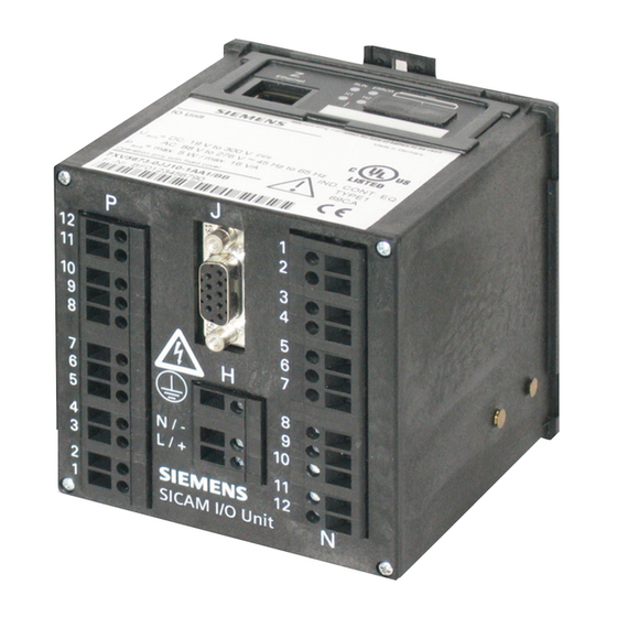
Interfaces 7XV5673-0JJ20-1AA1 7XV5673-0JJ10-1AA1 Figure 10-1 Connectors on the Terminal Side Terminals for supply voltage (H) and binary inputs and outputs (N, P) on the terminal side: Conductor cross-section 2.5 mm² (AWG 14) Conductor cross-section with 1.5 mm² bootlace ferrule (AWG 16) Tightening torque 0.4 Nm to 0.5 Nm (3.5 in-lb to 4.5 in-lb) - Page 26 DANGER Danger due to high voltages Non-observance will lead to death or serious injury. The protective earth terminal H must be con- nected to the protective earth conductor of the switch board or the control cabinet. DANGER Danger due Laser radiation! Class 1 Non-observance will lead to death or serious injury.
- Page 27 Terminal Function Description RS485 Serial interface: 7XV5673-0JJ10-1AA1 optical provided with an RS485 interface, 7XV5673-0JJ20- 1AA1 with an optical interface (FO). Ethernet Ethernet connection; on the top interface side of the housing Terminal Function Description Terminal block N Relay output 1, root Relay output 1, NO Relay output 2, root Relay output 2, NO...
- Page 28 Terminal Function Description Relay output 2, root Relay output 2, NO Relay output 3, NC Relay output 3, NO Relay output 3, root Binary input 1 Binary inputs 1+2 Binary input 2 Binary input 3 Binary input 3 Interference suppression capacitors at the relay con- tacts: ceramic, 4.7 nF, ±...
-
Page 29: Replacing The Battery
Replacing the Battery The battery must be replaced if it is no longer charged sufficiently (avoid complete discharging). In this case, the operational indication "Battery Failure" is gener- ated. This indication can also be configured to one of the 3 LEDs H1/H2/ERROR or to a relay output (see Device Manual SICAM I/O Unit 7XV5673, order num- ber E50417-H1040-C484). - Page 30 When the "Battery Failure" indication is displayed, replace the battery as follows: 1. Lever the cover of the battery compartment out of the socket with a suitable tool (e.g. precision engi- neer screwdriver 2.0 mm). Cover of battery compartment Figure 11-1 Removing the Cover of the Battery Compartment 2.
-
Page 31: Led Indications
6. Press the cover of the battery compartment back into the housing and make sure that it is in the cor- rect position. NOTES on Battery Disposal The battery used in this device contains lithium. It may only be replaced by electrically qualified personnel and disposed by authorized recycling companies. - Page 32 Meaning of the LEDs LED (green, red, yellow): On LED (green, red, yellow): Flashes LEDs H1/H2/ERROR: According to parame- terization LED: Off LED Speed (yellow): Off/On: 10/100 MBit/s LED Link / Activity (green): Lit: Ethernet link is up Flashes: Ethernet link is up, data transmission Off: No Ethernet partners connected LEDs Meaning...
- Page 33 LEDs Meaning Boot loader started after IP-Addr. push- ERROR button was pressed during power-on DHCP active (H1 switches off after ERROR reception of the IP address via DHCP) ERROR Default IP address by pressing the IP-Addr. push-button Boot loader started; no process application ERROR exists.
- Page 34 LEDs Meaning Boot loader started, process application is ERROR being loaded. Double IP address is detected. ERROR Process Application Normal mode ERROR ERROR IP address has been configured or received from DHCP. DHCP (LED RUN (green) is lit after the IP ERROR ERROR address is received by the DHCP server)
-
Page 35: Troubleshooting And Repair
(ESD). If you suspect that the device has a defect, Siemens recommends to send the entire device back to the manufacturer. If possible, use the original transport packaging or an equivalent packaging. -
Page 36: Storage And Transport
+10 °C to +35 °C (+50 °F to +95 °F). If the device is stored for an extended time, Siemens recommend to connect the device to the supply voltage for one or 2 days once a year, to reform the electrolytic capacitors in the device. -
Page 37: Technical Data (Selection)
Technical Data (Selection) NOTE For detailed information about the technical data, please refer the Device Manual SICAM I/ O Unit 7XV5673, order number E50417-H1040-C484. 15.1 Binary Inputs Maximum input voltage 300 V Logic levels of the input voltages ≥ 19 V At threshold voltage 19 V ≤... - Page 38 Switching time (OOT) ≤ 5 ms (OOT = Output Operating Time) additional delay of the out- put medium used Rated data of the output contacts 120 V ac 5.0 A, GP 277 V ac 5.0 A, GP 277 V ac 0.7 HP B300 R300...
- Page 39 15.4 Ethernet Protocols Modbus TCP Modbus UDP IEC 61850 Transmission rate 10/100 MBit/s Communication protocol Ethernet acc. to IEEE 802.3 Connection 100Base-T (RJ45) 100 Ω to 150 Ω STP, Cable for 100Base-T CAT5 Max. cable length 100Base-T 100 m (if routed well) Voltage strength DC 700 V 15.5 Serial Interface...
- Page 40 Bus protocol Modbus RTU Adjustable baud rates at 1200 bit/s Modbus RTU 2400 bit/s 4800 bit/s 9600 bit/s 19 200 bit/s 38 400 bit/s 57 600 bit/s 115 200 bit/s Adjustable baud rates at 1200 bit/s I/O mirror 2400 bit/s 4800 bit/s 9600 bit/s 19 200 bit/s...
- Page 41 15.7 Battery Type PANASONIC CR2032 VARTA 6032 101 501 Voltage Capacity 230 mAh Typical life time at permanently available power supply 10 years at not permanently available power supply 2 month within 10 years 15.8 Environmental Data Open type; surrounding air temperature: tsurr: max.
- Page 42 15.9 Additional Technical Data Internal fuse not replaceable type T1.6A/250V according to IEC 60127 Internal fuse, secondary not replaceable type F2A/125V according to UL 248-14 15.10 Protection Class According to IEC 60529 Terminal side IP20 DIN rail side IP20 Top side IP20 SICAM I/O Unit 7XV5673, Product Information E50417-B1050-C484-A3, Edition: 03.2012...
- Page 43 15.11 Dimensions Mass approx. 0.550 kg Dimensions (W x H x D) 96 mm x 96 mm x 100 mm 3.78 inch x 3.78 inch x 3.94 inch 111.3 (4.38) 103.8 (4.09) Dimensions in mm (inch) Figure 15-1 Dimension SICAM I/O Unit 7XV5673, Product Information E50417-B1050-C484-A3, Edition: 03.2012...
- Page 44 SICAM I/O Unit 7XV5673, Product Information E50417-B1050-C484-A3, Edition: 03.2012...
Need help?
Do you have a question about the SICAM 7XV5673 and is the answer not in the manual?
Questions and answers