
Related Manuals for Flowserve NAF ProCap


Summary of Contents for Flowserve NAF ProCap
- Page 1 NAF ProCap Capping Valve Installation Operation FCD NFENIM4155-00-A4 11/18 Maintenance Original Instructions These instructions must be read prior to installing, operating, and maintaining this equipment.
- Page 2 11/18 Copyright All rights reserved. No part of these instructions may be reproduced, stored in a retrieval system or transmitted in any form or by any means without prior permission of Flowserve Corporation. Disclaimer Information in this User Instruction is believed to be complete and reliable. In spite of all Flowserve’s efforts to provide comprehensive information and instructions,...
-
Page 3: Table Of Contents
NAF ProCap Capping Valve User Instruction – FCD NFENIM4155-00-A4 11/18 CONTENTS General Information ..........................3 Scope of manual ............................3 Valve design ..............................4 Safety Information ............................. 5 Intended use ..............................5 Receiving inspection ..........................6 Lifting and handling ........................... 6 Installation .............................. -
Page 4: General Information
If you have any doubt about the correct use and handling of a specific version of NAF ProCap Capping Valve, please contact your Flowserve representative. The instructions and list of spare parts in this document are applicable to the NAF ProCap Capping Valve in accordance with our Technical Bulletin NFENTB4155. -
Page 5: Valve Design
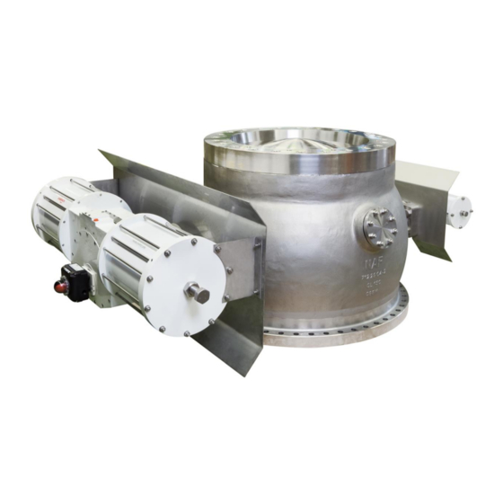
NAF ProCap Capping Valve User Instruction – FCD NFENIM4155-00-A4 11/18 Valve design The NAF ProCap Capping Valve is intended to be used in batch digesters. The valve is mounted to the top flange of the digester and it automates the filling of wood chips into the digester. -
Page 6: Safety Information
2 Safety Information Intended use • The NAF ProCap Capping Valve is intended to be used for filling of wooden chips into a batch digester. For any other use, please contact Flowserve NAF. -
Page 7: Receiving Inspection
NAF ProCap Capping Valve User Instruction – FCD NFENIM4155-00-A4 11/18 • When lifting the valve package, be aware of its weight and high centre of gravity! Please read instructions under 2.2 “Lifting” • If the valve has been delivered with the Pressure Safety Switch Unit option, please make sure to follow the instructions in Section 5.2 in order to... - Page 8 NAF ProCap Capping Valve User Instruction – FCD NFENIM4155-00-A4 11/18 the bigger sized actuator). See Figure 2. Table 1 shows approximate weight and lifting eye bolt thread sizes. Figure 2: Lifting of a NAF ProCap with mounted actuators. Weight Lifing Eye Bolts Size (approx.)
- Page 9 NAF ProCap Capping Valve User Instruction – FCD NFENIM4155-00-A4 11/18 below for disassembly and reassembly of the big actuator. For part numbers, see Figure 22 and Table 2. 1. Remove heat shield (65) by removing the 4 pcs screws indicated in Figure 3.
-
Page 10: Installation
5 Installation Mounting the ProCap valve on the digester The NAF ProCap capping valve is intended to be used for cooking of wooden chips in a batch digester. The valve shall be mounted to the digester top flange using the lower flange connection of the valve. -
Page 11: Option: Pressure Safety Switch Unit
As an option, a Pressure Safety Switch Unit can be delivered with the valve. It is delivered with two pressure switches which also can be integrated with the NAF ProCap Local Control Box. By having a double pipe connection, pressure can be detected even if one pipe is blocked. -
Page 12: Mounting Of The Pressure Safety Switch Unit To The Valve
NAF ProCap Capping Valve User Instruction – FCD NFENIM4155-00-A4 11/18 See Section 5.2.3 for safety locking of the valves during operation. Figure 4: Pressure Safety Switch Unit. Figure 5: Pressure Safety Switch Unit mounted on the ProCap valve 5.2.2 Mounting of the Pressure Safety Switch Unit to the valve... -
Page 13: Connecting The Pressure Switches To The Local Control Box
“1” when pressure <0.1 bar. The pressure switch type is of DPDT model and the connection terminal in the switch is seen below. If using the NAF ProCap Local Control Box, connect to switch 1 (see Figure 7). The signal/supply should go to 1C and the signal back to the box should be 1 N.C. -
Page 14: Flushing Of The Pressure Safety Switch Unit
NAF ProCap Capping Valve User Instruction – FCD NFENIM4155-00-A4 11/18 Figure 7. Terminal in pressure switch 5.2.5 Flushing of the Pressure Safety Switch Unit The Pressure Safety Switch Unit has a total of five ball valves integrated into a pipe loop. -
Page 15: Option: Local Control Box
NAF ProCap Capping Valve User Instruction – FCD NFENIM4155-00-A4 11/18 Option: Local Control Box The Local Control Box (see Figure 8) is a unit that greatly simplifies installation and automates the operating sequence (see Section 6.1) of the ProCap valve. It also grants the user the possibility to run a step-by-step open/close sequence of the valve and to get feedback to an independent safety system. -
Page 16: Local Control Box Design And Specifications
NAF ProCap Capping Valve User Instruction – FCD NFENIM4155-00-A4 11/18 5.3.1 Local Control Box design and specifications • Control Box material: AISI 316 • Supply voltage: 100-240 VAC • Signal: 24 VDC • Electrical cable entries: 12 pcs M20x1,5 • Max. allowed ambient temperature: 70°C •... -
Page 17: Function Modes
The Local Control Box cannot be maneuvered by using the green control knob. • “Off mode”: The Local Control Box is turned off. The NAF ProCap cannot be operated neither from the DCS nor manually from the green control knob. -
Page 18: Electric Wiring
This is a description for connecting the Local Control Box to customer DCS and how to connect the Local Control Box with the NAF ProCap Capping Valve. The NAF ProCap Local Control Box is wired according to drawing 33414591 (see Figure 10-14 below). - Page 19 NAF ProCap Capping Valve User Instruction – FCD NFENIM4155-00-A4 11/18 Terminal block section X0: Power Supply (see Figure 10) The Local Control Box uses a 100 – 240 VAC power supply. This, together with ground connection, is to be connected to section “X0” of the terminal block.
- Page 20 NAF ProCap Capping Valve User Instruction – FCD NFENIM4155-00-A4 11/18 Terminal block section X1 and X2: DCS signals and Independent Safety System (see Figure 11) • X1, Position 5 – 10: Local Control Box can be connected to DCS to send signal indicating o Position 5 –...
- Page 21 NAF ProCap Capping Valve User Instruction – FCD NFENIM4155-00-A4 11/18 Terminal block section X2: Inductive limit switches for jammers and valve position (see Figure 11) • Position 1 - 18: The connections between the Local Control Box and the limit switches for two jammers and valve open/closed.
- Page 22 NAF ProCap Capping Valve User Instruction – FCD NFENIM4155-00-A4 11/18 Terminal block section X2: Inductive limit switches for ball sector up/down, pressure switches, flushing valve and flushing flow switch (see Figure 13) • Position 19 - 24: The connections between the Local Control Box and ball sector up/down.
- Page 23 Y4: the ball sector up/down action (5/2 function, bi-stable) Please note that the solenoid valves are not provided with the Local Control Box. They can either be bought as a part of the NAF ProCap Pneumatic Cabinet (see Section 5.4) or installed by customer’s preference.
-
Page 24: Option: Pneumatic Cabinet
NAF ProCap Capping Valve User Instruction – FCD NFENIM4155-00-A4 11/18 Option: Pneumatic Cabinet The solenoid valves controlling the jammer and actuators for the ProCap can be mounted in several ways, including directly on the units, separately on a wall or in a rack. -
Page 25: Installation Of The Pneumatic Cabinet
NAF ProCap Capping Valve User Instruction – FCD NFENIM4155-00-A4 11/18 Figure 15: Pneumatic Cabinet 5.4.2 Installation of the Pneumatic Cabinet The Pneumatic Cabinet needs to be wired to the Local Control Box and pneumatically connected to the jammer and the pneumatic actuators. The electric wiring is described in Section 5.3.3. -
Page 26: Option: Water Mirror
NAF ProCap Capping Valve User Instruction – FCD NFENIM4155-00-A4 11/18 Figure 16. Pneumatic Chart (NAF Drawing 3340981) when used with Local Control Box Option: Water Mirror In many capping valve applications, there is an advantage adding a device called Water Mirror. The Water Mirror is mounted on top of the ProCap. The NAF Water Mirror is added to the NAF ProCap to: •... -
Page 27: Option: Flushing System
The NAF ProCap Flushing System effectively flushes the ball sector, removing all chips and fibers. The flushing system is preferably controlled from the Local Control Box, making sure that there is a water flush every time the valve is opened and closed. -
Page 28: Extra Flushinh Sequence
NAF ProCap Capping Valve User Instruction – FCD NFENIM4155-00-A4 11/18 • Water flow requirements: Normally 0.7-1.5 liters/sec depending on size of valve and amount of fibers to be flushed. Fig 18. Flushing System Note: The ball valve assembly and the flow switch are usually delivered as separate parts to be assembled according to customer requirements. - Page 29 NAF ProCap Capping Valve User Instruction – FCD NFENIM4155-00-A4 11/18 Fig 19. Extra flushing sequence In order to add this extra flushing, please adjust the time setting of the relay K8 (se Fig 8 and Fig 20) in the Local Control Box. Set the timescale for the dipswitches C1-C3 and adjust the time with the time delay adjustment trimmer B.
-
Page 30: Operation
6 Operation Operating sequence The NAF ProCap Capping Valve should be operated by the following sequence: 1. The ProCap is in the closed position. Cooking sequence has ended and the pressure switches indicate that there is no pressure in the digester. - Page 31 NAF ProCap Capping Valve User Instruction – FCD NFENIM4155-00-A4 11/18 Figure 21: Schematic figure Page 30 of 78 of the operating sequence...
-
Page 32: Bill Of Material And Recommended Spare Part Kits
NAF ProCap Capping Valve User Instruction – FCD NFENIM4155-00-A4 11/18 7 Bill of Materials and recommended spare part kits Figure 22: Exploded view with item/part numbering Page 31 of 78... - Page 33 NAF ProCap Capping Valve User Instruction – FCD NFENIM4155-00-A4 11/18 Kit A Kit B Kit C Item Part Clamp ring Seal kit Seat & seal kit complete Segment kit Body Ball Sector Stem, upper Stem, lower Eccenter, upper Eccenter, lower...
- Page 34 NAF ProCap Capping Valve User Instruction – FCD NFENIM4155-00-A4 11/18 Kit B Kit A Kit C Seal kit Item Part Clamp ring Seat & complete seal kit Segment kit Screw Screw O-ring O-ring O-ring O-ring Thread insert Cover ring, upper...
-
Page 35: Ordering Of Spare Parts
NAF ProCap. For replacement of all seals, the service center should use Kit B. If there is a need to replace the segment and seat, use Kit C in combination with Kit B. -
Page 36: Disassembling The Valve For Replacement Of The Clamp Ring Seals And The Seat Seal
NAF ProCap Capping Valve User Instruction – FCD NFENIM4155-00-A4 11/18 Disassembling the valve for replacement of clamp ring seals and seat seal Lock the control (i.e. Local Control Box) in order to prevent unintended stroking of the valve during maintenance. -
Page 37: Disassembling The Valve For Inspection And Replacement Of The Ball Sector, Seat And Stem Packing
For part numbers, refer to Figure 22 and table 2. Read Section 4, Lifting and Handling, before the valve is removed from the digester. Note: The instruction below is to be used when disassembling the NAF ProCap. If the instructions deviate from the ProCap that is to be disassembled or if you are uncertain on how to proceed, please contact NAF for further instructions. - Page 38 NAF ProCap Capping Valve User Instruction – FCD NFENIM4155-00-A4 11/18 3. Pressurize the small actuator (102). This enables movement of the ball sector (2). Remove the four bolts (33) situated on the back side of the small actuator mounting bracket and remove the small actuator from the stem.
- Page 39 NAF ProCap Capping Valve User Instruction – FCD NFENIM4155-00-A4 11/18 5. Mount slings on the jammer cylinders (24) but only lift loosely to avoid dropping the jammer plate (do not pull upwards as this will damage the jammer cylinders). Remove the four bolts (33) situated on the back side of the big actuator (101) mounting bracket.
- Page 40 NAF ProCap Capping Valve User Instruction – FCD NFENIM4155-00-A4 11/18 8. Remove bolt and washer from the expansion pins on each side of the ball sector. 9. Rotate the ball sector 90°. Place a small piece of wood (or similar item that does not damage the ball sector) to let the ball sector rest on.
- Page 41 NAF ProCap Capping Valve User Instruction – FCD NFENIM4155-00-A4 11/18 10. Screw the expansion pin removal unit in place in the expansion pins. Make sure that it is screwed down all the way to avoid damage to the unit. 11. Place the removal rod in the grove of the expansion pin removal unit on one side of the ball sector and hit the removal rod with a sledge hammer to remove the expansion pin.
- Page 42 NAF ProCap Capping Valve User Instruction – FCD NFENIM4155-00-A4 11/18 14. Remove the keys from both stems. 15. Remove the screws from the gas cover on the big stem and then remove gas cover (not seen in pictures above). 16. Remove the cover from the big stem.
- Page 43 NAF ProCap Capping Valve User Instruction – FCD NFENIM4155-00-A4 11/18 19. Unscrew the screws on the eccentric hub on the big stem. 20. Unscrew the cover on the eccentric hub on the small stem. 21. Apply the distance plates between the ball sector and the body on each side, this to prevent force to be applied on the ball sector in the next step.
- Page 44 NAF ProCap Capping Valve User Instruction – FCD NFENIM4155-00-A4 11/18 24. Install the actuator cover plate. This enables force to be applied on the other stem. Do not attempt to use any other equipment as this might cause damage to the ball sector.
- Page 45 NAF ProCap Capping Valve User Instruction – FCD NFENIM4155-00-A4 11/18 26. Start to lift the ball sector gently. This is to be done in iterations by: a. Lift the ball sector 2 – 3 cm b. Lower the chain block side but do not touch the seat ring After some iterations, the ball sector is carried by the long round string only.
- Page 46 NAF ProCap Capping Valve User Instruction – FCD NFENIM4155-00-A4 11/18 27. Before lifting the ball sector out of the valve body, place a piece of cardboard, blanket or other protective material between the ball sector and the valve body. Lift out the ball sector out of the valve body gently.
- Page 47 NAF ProCap Capping Valve User Instruction – FCD NFENIM4155-00-A4 11/18 28. Place the ball sector on a covered pallet. Page 46 of 78...
- Page 48 NAF ProCap Capping Valve User Instruction – FCD NFENIM4155-00-A4 11/18 29. Hang a sling around each stem of the valve body, preferably using a crane or a forklift for a controlled simultaneous lift. Slowly lift the ProCap some 30 cm for the floor.
- Page 49 NAF ProCap Capping Valve User Instruction – FCD NFENIM4155-00-A4 11/18 31. In a controlled manner, start to raise the upper flange thus turning the valve. Control the forklift levels upward/downwards for a controlled rotation. When the valve is fully turned, lower it onto a protected and clean surface.
- Page 50 NAF ProCap Capping Valve User Instruction – FCD NFENIM4155-00-A4 11/18 Page 49 of 78...
- Page 51 NAF ProCap Capping Valve User Instruction – FCD NFENIM4155-00-A4 11/18 32. Apply a rust penetrant spray on each bolt on the clamp ring. Let it sit for a short time. Remove the bolts using a suitable (power) tool. If the bolts are stuck, gentle heating may be applied.
- Page 52 NAF ProCap Capping Valve User Instruction – FCD NFENIM4155-00-A4 11/18 Page 51 of 78...
-
Page 53: Re-Assembly Of The Naf Procap
For part numbers, refer to Figure 18. Read Section 4, Lifting and Handling, before the valve is put back onto the digester. The instruction below is to be used when re-assembling the NAF ProCap. If the instructions deviate from the ProCap that is to be assembled, or if you are uncertain on how to proceed, please contact Flowserve NAF for further instructions. - Page 54 NAF ProCap Capping Valve User Instruction – FCD NFENIM4155-00-A4 11/18 37. Hang a round sling around each stem of the valve body, preferably using a forklift for a controlled simultaneous lift. Slowly lift the ProCap some 30 cm for the floor. Turn the valve in a controlled manner.
- Page 55 NAF ProCap Capping Valve User Instruction – FCD NFENIM4155-00-A4 11/18 39. Put a round sling (one short and one long) around each expansion pins and install the expansion pins loosely. Connect lifting devices to each round sling. The short one is to be connected to a chain block.
- Page 56 NAF ProCap Capping Valve User Instruction – FCD NFENIM4155-00-A4 11/18 40. Identify by the markings on the ball sector/stem (made during disassembly) which orientation the ball sector should have in the valve body. 41. When inserting the ball sector into of the valve body, place a piece of cardboard, blanket or other protective material between the ball sector and the valve body.
- Page 57 NAF ProCap Capping Valve User Instruction – FCD NFENIM4155-00-A4 11/18 42. The ball sector shall be tilted up once in the valve body when close to the seat ring. This is to be done in iterations by: a. Raise the chain block side but do not touch the seat ring b.
- Page 58 NAF ProCap Capping Valve User Instruction – FCD NFENIM4155-00-A4 11/18 43. Add O-rings and the Metaloplast bushing using the clamp tool on the small stem eccenter. Add the support ring. Add the O-ring onto the support ring. Grease the upper part of the eccenter once that O-ring is in place.
- Page 59 NAF ProCap Capping Valve User Instruction – FCD NFENIM4155-00-A4 11/18 44. Add the O-ring to the small eccenter stem neck and spray silicone into the small eccenter stem neck. Page 58 of 78...
- Page 60 NAF ProCap Capping Valve User Instruction – FCD NFENIM4155-00-A4 11/18 45. Insert the small eccenter stem into the valve body. This is done by pushing it through the clamp tool and into the body. It is of great importance that the O-ring in the support ring is not folded.
- Page 61 NAF ProCap Capping Valve User Instruction – FCD NFENIM4155-00-A4 11/18 46. “Glue” the Metaloplast bushing in place on the small eccenter lid using grease and screw the lid onto the small eccenter stem. Page 60 of 78...
- Page 62 NAF ProCap Capping Valve User Instruction – FCD NFENIM4155-00-A4 11/18 47. Add the O-rings to the big stem and big eccenter. Add the Metaloplast bushing to the eccenter. Mark the end position of the stem with a marker, this to avoid that the O-rings of the stem follow the Metaloplast bushing when the stem is put in place.
- Page 63 NAF ProCap Capping Valve User Instruction – FCD NFENIM4155-00-A4 11/18 48. Insert the big stem into the eccenter and insert the stem package into the valve body. Once in place, put paste on the bolts and attach the eccenter with these.
- Page 64 NAF ProCap Capping Valve User Instruction – FCD NFENIM4155-00-A4 11/18 54. When the small stem is in place, put the expansion pins in place on both stems and tighten. Page 63 of 78...
- Page 65 NAF ProCap Capping Valve User Instruction – FCD NFENIM4155-00-A4 11/18 55. To get the small eccenter to raise/lower the ball sector properly, the small stem should “be tight” at some 350 dgs (where 360 dgs is 12 o’clock). This is to be adjusted with big eccenter (by first removing the lid).
- Page 66 NAF ProCap Capping Valve User Instruction – FCD NFENIM4155-00-A4 11/18 59. Mount round slings on the jammer cylinders on the jammer plate. Pressurize the jammer cylinders into “open” position. 60. Move the jammer plate into the correct position i.e. the jammer cylinders can lock into the jammer hub.
- Page 67 NAF ProCap Capping Valve User Instruction – FCD NFENIM4155-00-A4 11/18 64. In a controlled manner, start to raise the upper flange thus turning the valve. Control the forklift levels upward/downwards for a controlled rotation. When the valve is fully turned, lower it onto a protected and clean surface.
- Page 68 NAF ProCap Capping Valve User Instruction – FCD NFENIM4155-00-A4 11/18 Page 67 of 78...
- Page 69 NAF ProCap Capping Valve User Instruction – FCD NFENIM4155-00-A4 11/18 65. Place a distance to the floor to enable the ball sector to be moved freely (as well as avoiding damaging it). Set down the valve on the floor/distance. 66. Mount the big actuator.
- Page 70 NAF ProCap Capping Valve User Instruction – FCD NFENIM4155-00-A4 11/18 80. When the clamp ring is removed, remove distance in the area between the seat ring and the valve body. 81. Add the seal ring to the clamp ring. 82. Grease the O-rings and add them to the clamp ring.
- Page 71 NAF ProCap Capping Valve User Instruction – FCD NFENIM4155-00-A4 11/18 89. Tighten the stop screws on the opening side of the small actuator. 90. Perform action “raise the ball sector” on the small actuator. 91. The valve is now assembled. Add any auxiliary equipment and test the valve with water.
-
Page 72: Returns And Disposal
NAF ProCap Capping Valve User Instruction – FCD NFENIM4155-00-A4 11/18 10 Returns and Disposal 10.1 Returns The product/system shall be emptied, cleaned, and preserved before returning the equipment to the manufacturer. The manufacturer will only open the returned equipment if the contamination declaration is present. -
Page 73: Annex A: Electric Wiring Of The Local Control Box. Drawing 33414591, Part 1
NAF ProCap Capping Valve User Instruction – FCD NFENIM4155-00-A4 11/18 Annex A: Electric wiring of the Local Control Box. Drawing 33414591, part 1: Terminal X0 and X1: Power supply and remote control Page 72 of 78... -
Page 74: Annex B: Electric Wiring Of The Local Control Box. Drawing 33414591, Part 2
NAF ProCap Capping Valve User Instruction – FCD NFENIM4155-00-A4 11/18 Annex B: Electric wiring of the Local Control Box Drawing 33414591, part 2: Terminal X1 and X2: Signals back to DCS plus Independent Safety System including extra limit switches for jammers and closed valve. -
Page 75: Annex C: Electric Wiring Of The Local Control Box. Drawing 33414591, Part 3
NAF ProCap Capping Valve User Instruction – FCD NFENIM4155-00-A4 11/18 Annex C: Electric wiring of the Local Control Box. Drawing 33414591, part 3: Terminal X2: Inductive limit switches for jammers and valve position. Page 74 of 78... -
Page 76: Annex D: Electric Wiring Of The Local Control Box. Drawing 33414591, Part 4
NAF ProCap Capping Valve User Instruction – FCD NFENIM4155-00-A4 11/18 Annex D : Electric wiring of the Local Control Box. Drawing 33414591, part 4: Terminal X2: Inductive limit switches for ball sector up/down, pressure switches and flushing valve and flushing flow switch. -
Page 77: Annex E: Electric Wiring Of The Local Control Box. Drawing 33414591, Part 5
NAF ProCap Capping Valve User Instruction – FCD NFENIM4155-00-A4 11/18 Annex E: Electric wiring of the Local Control Box. Drawing 33414591, part 5: Terminal X3: Solenoid valves. Page 76 of 78... -
Page 78: Annex F: Logic Sequence For Open & Close Sequence Of Local Control Box
NAF ProCap Capping Valve User Instruction – FCD NFENIM4155-00-A4 11/18 Annex F: Logic sequence for Open & Close sequence for ProCap. (Please note that this is only provided as an example. We always recommend to use the Local Control Box for a well proven and safe control sequence, which also controls a flushing sequence). - Page 79 Flowserve Corporation has established industry leadership in the design and manufacture of its products. When properly selected, this Flowserve product is designed to perform its intended function safely during its useful life. However, the purchaser or user of Flowserve products should be aware that Flowserve product might be used in numerous application under a wide variety of industrial service conditions.
Need help?
Do you have a question about the NAF ProCap and is the answer not in the manual?
Questions and answers