
Related Manuals for Flowserve Nordstrom Dynamic Balance


Summary of Contents for Flowserve Nordstrom Dynamic Balance
- Page 1 Dynamic Balance Plug Valve ® and Double DB Plug Valve ® Installation, Operation and Maintenance FCD NVENIM2005-01 (Replaces V170-PED) Nordstrom Valves...
-
Page 2: Table Of Contents
Contents 1 Valve Selection 1.1 Introduction 1.2 Pressure-Temperature Rating 1.3 Bending Strength 1.4 Fire Safety 1.5 Pressure Surge 1.6 Throttling Service 1.7 Temperature Changes 1.8 Other Pressurization 1.9 Trapped Pressure 1.10 Material Compatibility 1.11 Operating Effort 2 Shipping And Storage 2.1 Introduction 2.2 Handling 2.3 Storage... - Page 3 7 Technical Data 7.1 Part Identification Reference 7.2 Exploded Views 7.3 Detail Sketches 8 Procedure for Tightening Cap Screws and Nuts 9 Tables Figures Figure 1 – Illustration of typical nameplate Figure 2 – Location of Relief Fitting Figure 3 – Gauge Figure 4 –...
-
Page 4: Valve Selection
Flow Control Nordstrom Valves 1 Valve Selection 1.3 Bending Strength Piping systems are subject to mechanical constraints at fixed 1.1 Introduction support points such as rigid nozzles, anchors, etc. Cold springing at assembly, system temperature changes, together with gravity, It is beyond the scope of this manual to make recommendations possible inertia loads, landslides, nonuniform subsidence in buried for specific applications. -
Page 5: Pressure Surge
When compatibility is a concern, guid- ance should be obtained from informed sources such as Flowserve Flowserve personnel should be consulted on proper valve selection or the system’s engineers. -
Page 6: Operating Effort
“cheaters”. Flowserve should be consulted for specific instruction on operating If outdoor storage is unavoidable, valves should be supported off the torques. -
Page 7: Threaded Valve To Pipe Assembly
Flow Control Nordstrom Valves b. Note any special warning tags or plates attached to or accompa- e. Assemble the joint wrench-tight. The wrench on the valve should nying the valve, and take appropriate action. be on the valve end into which the pipe is being threaded. c. -
Page 8: Weld Joint Assembly
Flow Control Nordstrom Valves grooved, jacketed, corrugated, or spiral wound) should not be CAUTION: This guide is not a complete welding instruction. used with these flanges. All welding should be in accordance with all codes and/or jurisdictional regulations applicable to the construction d. -
Page 9: Testing And Adjustment
Actuator selection and adjustments should normally be made by element in these types of valves is very important. In some cases Flowserve based on published literature and/or technical advice the effort required to move the closure element might increase sub-... -
Page 10: Fluid Dynamics Of Shutoff Valve Operation
Flow Control Nordstrom Valves of actuator manufacturer. Flowserve should be consulted when a pressure in that section of piping. Therefore, a slow closing is helpful manually operated valve must be retrofitted with a power actuator. in limiting the magnitude of the pressure surge phenomena. -
Page 11: Maintenance
Valves are properly considered to be a hybrid structure, a combina- company’s safety procedures. tion of a pressure vessel and operating machinery. Maintenance pro- If anything in this manual is unclear, contact the Flowserve Sulphur cedures, therefore, must reflect the requirements of the occasional Springs Customer Service Department for assistance. -
Page 12: When You Call Or Write Us
Invensys companies, merged as Nordstrom Audco Inc.; 3. The valve is tested to new valve standards. • In 2002 Flowserve Corporation acquired the Flow Control Division of Invensys, and Nordstrom Audco Inc., was renamed Flowserve 4. A like-new valve is provided at a fraction of a new valve cost. -
Page 13: Video Training
It is often difficult to schedule training in one place and time suitable protects the cover bolting from corrosive agents by enclosing for all of the people who need to attend. Flowserve Sulphur Springs sealant in the area between the Body and Cover. The Weatherseal... -
Page 14: Sealant System
3. The Cover prevents external leakage and is designed to allow a finite floating of the Plug. 2. Stem Packing. Specially designed by Flowserve Sulphur Springs. Manufactured from a compound of graphite and PTFE, the stem 4. The Adjustment Member is provided so that the position of the packing is pressure-energized (no external adjustments are needed) Plug can be set in the proper relation to the Body. -
Page 15: Valve Front Identification
During operation, all parts of the gearing have free movement. 5.17 Sealant Injection Equipment 5.15 Sealants Flowserve Sulphur Springs offers five types of heavy-duty valve seal- Valve sealant is a viscous material that resists chemical attack and ant injection equipment, designed to correspond to the type of use the dissolving characteristics of line media. -
Page 16: Valve Maintenance
Flow Control Nordstrom Valves 5.18 Valve Maintenance maintenance procedures, found in the specific valve mainte- nance manual, to ensure that the valves are operating at their Proper valve performance depends on: peak condition. Figure 3 – Gauge • Periodic injection of sealant to maintain adequate sealant pressure in the valve to ensure positive shutoff and smooth operation. -
Page 17: Valve Maintenance: Troubleshooting
Flow Control Nordstrom Valves even after you have injected more than enough sealant to fill the your valve problem. Your sealant injection equipment should be valve. operating properly prior to diagnosing valve problems. This scenario signals one of the following conditions: CAUTION: If a non-compressible fluid is trapped in the center cavity of the Plug, when the valve is in the closed a. - Page 18 Flow Control Nordstrom Valves 4. Loosen the Plug Adjusting Screw ⁄ turn. If possible, the valve 9. Inject sealant: Refer to Problem C. should be in the full open position for final plug adjustment. 10. Adjust the Plug as described in Valve Seat Leakage, Cause A2 5.
- Page 19 Flow Control Nordstrom Valves Cause B4: Severe Stem corrosion (wrench-operated valves) 4. Replace the Gearing less the Segment Key. Solution B4 5. Rotate the Handwheel to operate the Gearing. If the Gearing is Remove corrosion from the Stem and interior surface of the Gland difficult to operate, the problem is in the Gearing.
- Page 20 4. Using a .188" square tool or a 1/4" Hex wrench, remove the Check exposes the Plug Adjusting Screw, the threads of which have Valve. been treated with a thread-locking compound at the Flowserve Sulphur Springs factory. 5. Once the Check Valve has been removed, clean the removal area of all debris and check for thread damage.
- Page 21 Flow Control Nordstrom Valves 4. If the valve is installed vertically, support may be required for the a. Insert the proper sized hex-head wrench into the hex hole in Cover so that the internal parts, retained by the Cover, will not the Plug Adjusting Screw.
- Page 22 Flow Control Nordstrom Valves Problem E: Leakage at the Stem 9. Install the Gland and Gland Retainer if so equiped. a. Straightway valves: Apply a thin film of good-quality gasket Cause E1: Line pressure bypassing Stem Packing compound to the mating surface of the Body or Gland and Solution E1 install the Gland.
-
Page 23: Technical Data
Flow Control Nordstrom Valves 7 Technical Data 7.1 Part Identification Reference Part Name Part Name Body Button Head Fitting Plug Cover Weatherseal Cover Plug Spring Disk Bolting for Cover Upper Bearing Button Plug Stem Lower Bearing Button Equalizer Balance Ball Plug Adjusting Screw* Balance Spring Cover*... -
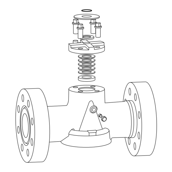
Page 24: Exploded Views
Flow Control Nordstrom Valves 7.2 Exploded Views Figure 4 – Wrench-Operated Valve Dynamic Balance Plug Valve and Double DB Double Isolation Plug Valve FCD NVENIM2005-01 ® ®... -
Page 25: Detail Sketches
Flow Control Nordstrom Valves 7.3 Detail Sketches Figure 5 – Stem End Detail: Wrench-Operated Valve 22, 23 *Applies to Size 6 and Larger only. Refer to Figure 7. Figure 6 – Stem End Detail: Gear-Operated with Bolt-on Gear Flange FCD NVENIM2005-01 Dynamic Balance Plug Valve and Double DB Double Isolation Plug Valve... -
Page 26: Figure 7 - Stem End Detail: Gear-Operated With Cast On Gear Flange
Flow Control Nordstrom Valves Figure 7 – Stem End Detail: Gear-Operated with Cast On Gear Flange Dynamic Balance Plug Valve and Double DB Double Isolation Plug Valve FCD NVENIM2005-01 ® ®... -
Page 27: Figure 8 - Cover End Detail: Size 6 And Larger With Pressure Seal Arrangement
Flow Control Nordstrom Valves Figure 8 – Cover End Detail: Size 6 and Larger with Pressure Seal Arrangement Figure 9 – Cover End Detail: Size 6 and Larger with Spring Disk Arrangement FCD NVENIM2005-01 Dynamic Balance Plug Valve and Double DB Double Isolation Plug Valve ®... -
Page 28: Figure 10 - Cover End Detail: Size 6 And Larger With Ball Seat Arrangement
Flow Control Nordstrom Valves Figure 10 – Cover End Detail: Size 6 and Larger with Ball Seat Arrangement Figure 11 – Cover End Detail: Size 4 and Smaller Dynamic Balance Plug Valve and Double DB Double Isolation Plug Valve FCD NVENIM2005-01 ®... -
Page 29: Procedure For Tightening Cap Screws And Nuts
Figure 12 – Bolt-tightening patterns Cap Screws and Nuts NOTE: This procedure is intended only as a guide. It is impossible for Flowserve to anticipate all field-site conditions, so rely on your own judgment and experience. 1. Inspect applicable parts to be sure that: a. -
Page 30: Tables
Flow Control Nordstrom Valves 9 Tables Table 3 – Size 6 and Larger Valve Pressure Retaining Bolting (all parts) Torque Values for Pressure Retaining Bolting Torque (ft-lb) Thread Size Table 1– Size 4 and Smaller Valve Gland Bolting Minimum Maximum Torque (ft-lb) 1/4 –... -
Page 31: Table 4 - Plug Adjusting Screw Torque Values
Flow Control Nordstrom Valves Plug Adjusting Screw Torque Values Table 4 – Plug Adjusting Screw Torque Values (continued) Valve Final The torque values listed in the following table are based on the Basic Figure Numbers Initial ft-lb Size ft-lb torque used during assembly of Dynamic Balance Plug Valves at 1949, 2045, 2049 the factory. -
Page 32: Table 5 - Sealant Capacities
Flow Control Nordstrom Valves Sealant Capacities The following information is intended only as a guide to assist you in determining the approximate amount of sealant that is required to service a valve with sealant. The capacities shown are for valves that are empty of sealant. Table 5 –... - Page 33 Flow Control Nordstrom Valves FCD NVENIM2005-01 Dynamic Balance Plug Valve and Double DB Double Isolation Plug Valve ® ®...
- Page 34 Flow Control Nordstrom Valves Dynamic Balance Plug Valve and Double DB Double Isolation Plug Valve FCD NVENIM2005-01 ® ®...
- Page 35 Flow Control Nordstrom Valves FCD NVENIM2005-01 Dynamic Balance Plug Valve and Double DB Double Isolation Plug Valve ® ®...
- Page 36 All other countries Phone: (903) 885-4692 Phone: Fax: (903) 439-3404 (903) 885-4691 (903) 885-4693 (800) 225-6989 Fax: (903) 439-3411 (Part V170-PED) © 2011 Flowserve Corporation, Irving, Texas, USA. Flowserve is a registered trademark of Flowserve Corporation. FCD NVENIM2005-01 Printed in USA.
Need help?
Do you have a question about the Nordstrom Dynamic Balance and is the answer not in the manual?
Questions and answers