Table of Contents
Advertisement
Quick Links
Valves for corrosive applications
Series 132000
Index
1
Using Flowserve valves and actuators correctly
2
Transport and storage
3
Installation
4
Intended use
5
Installation
6
Pressure test pipe section
7
Normal operation and maintenance
8
Trouble-shooting
9
Product description
10
Bonnet
11
Plug and seat
12
Bellows seal
13
Stem
14
Packing
15
Test connection
16
Quick check
17
Masintenance
18
Remove actuator from valve
19
Instal actuator on valve
20
Disassemble valve
21
Assemble valve
22
Trouble-shooting chart
1
U S I N G K Ä M M E R V A L V E S A N D A C T U A T O R S
CORRECTLY
1.1
Use
FLOWSERVE control valves and actuators are intended
exclusively for control of mediums in an approved
pressure and temperature range after installation in a
piping system and connection of the actuator to the
control system.
The permissible pressure and temperature limits are
defined in the operating instructions for the individual
valve series.
KMEIM3202-01 -02.04
1.2
Terms concerning safety
The safety terms DANGER, WARNING, CAUTION and
NOTE are used in these instructions to highlight
particular dangers and/or to provide additional
information on aspects that may not be readily
apparent.
DANGER: indicates that death, severe personal injury
and/or substantial property damage will occur if proper
precautions are not taken.
STOP!
WARNING: indicates that death, severe personal injury
and/or substantial property damage can occur if proper
precautions are not taken.
CAUTION: indicates that minor personal injury and/or
property damage can occur if proper precautions are
not taken.
NOTE: indicates and provides additional technical
information, which may not be very obvious even to
qualified personnel. Compliance with other, not
particularly emphasised notes, with regard to
transport, assembly, operation and maintenance and
with regard to technical documentation (e.g. in the
operating instruction, product documentation or on
the product itself) is essential, in order to avoid faults,
which in themselves might directly or indirectly cause
severe personal injury or property damage.
1.3
Safety Notes for Operator
The manufacturer is not responsible for the following
and it is therefore necessary to ensure the following
when using FLOWSERVE control valves:
1.3.1 Use valve as intended (Section 1)
DANGER: Never operate a control valve whose
approved pressure/temperature range according to
the applicable documentation for the valve series is
not sufficient for the operating conditions. Moreover,
it must be ensured that the valve is approved for the
operating medium:
Flow Control Division
Kammer Control Valves
1
Advertisement
Table of Contents

Related Manuals for Flowserve Kammer 132000 Series


Summary of Contents for Flowserve Kammer 132000 Series
- Page 1 CORRECTLY and it is therefore necessary to ensure the following when using FLOWSERVE control valves: FLOWSERVE control valves and actuators are intended 1.3.1 Use valve as intended (Section 1) exclusively for control of mediums in an approved pressure and temperature range after installation in a...
-
Page 2: Transport And Storage
Valves properly and checked regularly. The wall thicknesses of the FLOWSERVE control valves correspond to the heavier than approx. 10 kg should be stored and transported on a pallet (or similarly supported, where standards and regulations for the pressure stage requirements of the piping system in question. -
Page 3: Intended Use
INTENDED USE EN 13463-1 by the manufacturer and satisfy the The series 132000 valves from Flowserve Essen GmbH requirements. can be installed in all areas endangered by gas 4.2.2 The valve body for the valves consists of cast iron. - Page 4 Flow Control Division Kammer Control Valves INSTALLATION When inserting the valve into a pipeline already WARNING: Plastic liners on the valves require installed, the distance between the ends of the pipeline particular protection before/during installation; STOP! must be sufficient to prevent damage to any of the therefore: sealing surfaces.
-
Page 5: Normal Operation And Maintenance
Flow Control Division Kammer Control Valves PRESSURE TESTING PIPING SECTION The valve has already been pressure-tested by the The liner thickness is at least 5 mm for DN25 and higher manufacturer. When pressure testing a section of the and 3.5 mm for DN15 and DN20. pipeline with valves installed, observe the following: First thoroughly flush newly installed piping systems to Table 2a: Body specifications... - Page 6 Flow Control Division Kammer Control Valves Table 3: Kvs / Cv values Size DIN 80 100 Size ANSI 0,5 0,75 Stroke (mm) 0,011 0,013 50 : 1 Hast C276* Hast C276* 0,017 0,020 50 : 1 Hast C276* Hast C276* 0,025 0,029 50 : 1 Hast C276* Hast C276*...
-
Page 7: Maintenance
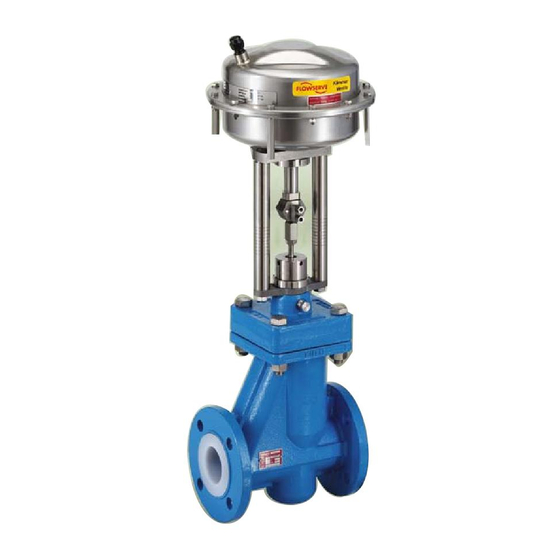
Flow Control Division Kammer Control Valves STEM The valve stem is equipped with a blowout protection MAINTENANCE feature. This ensures that the valve stem cannot be Check for proper function at regular intervals as follows. removed from the top of the valve. This is an important These checks can be accomplished in the installed state safety factor when the actuator is removed from the and, in many cases, without shutting down production. - Page 8 Flow Control Division Kammer Control Valves Actuator stem Coupling Coupling screw Coupling insert Locknut Packing nut Yoke plate Slotted nut Yoke rod nut Plug stem Test connection (drawn rotated 90°) Bonnet bolt Bonnet O-Ring (body/bonnet) Bellows seal Insert, thread lock Body Plug Seat...
- Page 9 Flow Control Division Kammer Control Valves REMOVING ACTUATOR FROM VALVE (See Fig. 1) 18.1 Shut off air supply. DANGER: ..Ensure that actuator is not under pressure and drain process medium before performing maintenance work. Failure to observe can lead to serious injuries.
- Page 10 Flow Control Division Kammer Control Valves Bellows seal O-Ring Plug Insert, thread lock Seat Body Plug Seal (G only with adapter) Bushing Bonnet Screw Slotted nut Stem Packing Packing follower Packing nut Fig. 2: Individual parts for series 132 000 (also see spare parts lists) Table 6: Tightening toque for seat (Nm) DN 15...
- Page 11 (see Fig. 2) 21.1 Replace all worn or damaged parts. Use only genuine FLOWSERVE parts. Parts to be reused must be clean. DANGER: Since toxic or hazardous substances could be Always replace parts subject to wear such as gaskets, present, release all pressure in the system and drain all packings and O-rings.
-
Page 12: Troubleshooting Chart
12, av. du Québec 91965, Courtaboeuf Cedex France Telephone: +33 (0) 1 60 923 251 Facsimile: +33 (0) 1 60 923 299 All data subject to change without notice ©09.2003 Flowserve Corporation. Flowserve and Kämmer are trademarks of Flowserve Corporation...
Need help?
Do you have a question about the Kammer 132000 Series and is the answer not in the manual?
Questions and answers