Table of Contents

Related Manuals for Flowserve Atomac AKH3.2


Summary of Contents for Flowserve Atomac AKH3.2
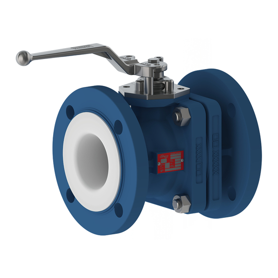
- Page 1 Atomac AKH3.2 Lined Reduced Port Ball Valve AKH3.2M (Monobloc) & AKH3.2F (Floating Ball) FCD ATENIM0001-03 (EN/AQ) Original Instructions These instructions must be read prior to installing, operating, and maintaining this equipment.
- Page 2 AKH3.2 User Instruction – FCD ATENIM0001 EN Copyright All rights reserved. No part of these instructions may be reproduced, stored in a retrieval system or transmitted in any form or by any means without prior permission of Flowserve Corporation. Document Version Revision 03, 09-August-2022...
-
Page 3: Table Of Contents
AKH3.2 User Instruction – FCD ATENIM0001 EN CONTENTS General Information ......................... 4 Scope of manual ............................4 Disclaimer ..............................4 Certification instruction ..........................4 Units ................................4 Safety Information ........................... 5 Intended use ..............................5 Safety symbols and description ........................6 General hazard sources .......................... - Page 4 AKH3.2 User Instruction – FCD ATENIM0001 EN Decommissioning and Recommissioning .................. 28 Decommissioning ............................28 Recommissioning ............................28 10 Returns and Disposal ........................29 10.1 Returns ............................... 29 10.2 Disposal and recycling ..........................29 11 Technical Data ..........................30 11.1 Weights ...............................
-
Page 5: General Information
Disclaimer Information in this User Instruction is believed to be complete and reliable. In spite of all Flowserve’s efforts to provide comprehensive information and instructions, sound engineering and safety practices should always be used. -
Page 6: Safety Information
(Flowserve Ahaus GmbH can give recommendations). The product/system must not be operated beyond the parameters specified for the application. If there is any doubt as to the suitability of the product/system for the application intended, contact Flowserve for advice, quoting the serial number. -
Page 7: Safety Symbols And Description
AKH3.2 User Instruction – FCD ATENIM0001 EN Safety symbols and description This User Instruction contains specific safety markings where non-observance of an instruction would cause a hazard. The specific safety markings are: Table 2: Definition of safety symbols and markings Symbol Description DANGER... -
Page 8: General Hazard Sources
AKH3.2 User Instruction – FCD ATENIM0001 EN Table 3: Additional symbols Symbol Description ELECTRICAL HAZARD This symbol indicates electrical safety instructions where non- compliance would affect personal safety and could result in loss of life. TOXIC HAZARD This symbol indicates “hazardous substances and toxic fluid” safety instructions where non-compliance would affect personal safety and would damage the equipment or property. -
Page 9: Safety Data Sheets
2.3.1 Mechanical Hazards Lifting limits and guidelines Note: The load values mentioned in this section are Flowserve recommendations only. All liftings must be done in compliance with site safety protocol, local regulations, and related industry standards. Many precision parts have sharp corners which require appropriate personal protective equipment during handling. -
Page 10: Potential Explosive Areas
Consideration of Conformity with the Directive 2014/34/EU (ATEX) The lined and metallic valves of the brands Atomac and Durco produced by Flowserve Ahaus GmbH have been examined according to DIN EN 13463-1 to determine the danger of ignition. Potential sources of ignition coming from the valve itself have not been ascertained. -
Page 11: Scope Of Delivery
AKH3.2 User Instruction – FCD ATENIM0001 EN Gland Seal is accomplished by 2 different packing options: • Top Cap with belleville washers for life loaded packing. • Re-Adjustable packing gland follower. Both options fullfill the requirements and acceptance criteria for fugitive emission per ISO 15848, API 641. The unit comes with a 1 layer epoxy paint with a minimum layer thickness of 60 µm, other paint finishes are available on request. -
Page 12: Connections
AKH3.2 User Instruction – FCD ATENIM0001 EN Connections 3.4.1 Dimensions drawing AKH3.2M & AKH3.2F Figure 2: Dimensions drawing Table 4: Dimensions for AKH3.2, dimensions in mm [in.] DN [NPS] ØR 025 [1] [5.0] [2.2] 11.5 [0.45] [2.0] 040 [1.5] [6.5] [2.95] [0.55] [2.87]... - Page 13 AKH3.2 User Instruction – FCD ATENIM0001 EN 3.4.2 Auxiliary connections (Top Cap) Figure 3: Top Work drawing (Top Cap) Table 5: Top Work dimensions (Top Cap), dimensions in mm [in.] DN [NPS] ØA 025 [1] [0.39] [0.31] [0.37] 040 [1.5] [0.39] [0.31] [0.37]...
- Page 14 AKH3.2 User Instruction – FCD ATENIM0001 EN 3.4.3 Auxiliary connections (Gland Follower) Figure 4: Top Work drawing (Gland Follower) Table 6: Top Work dimensions (Gland Follower), dimensions in mm [in.] DN [NPS] ØA 025 [1] [0.39] [0.31] [0.37] [0.94] 040 [1.5] [0.39] [0.31] [0.37]...
-
Page 15: Accessories
AKH3.2 User Instruction – FCD ATENIM0001 EN Accessories Manual and Automated Operations Atomac lined valve are equipped with lockable lever as a standard. Larger valves are equipped by request with a manual gear. The modular construction of lined Atomac valves allows are easy use of all types of pneumatic or electric actuation systems. Due to the ISO 5211 universal mounting pad, actuators can be mounted to the valves on-site, without removing them from the pipeline. - Page 16 As there are special requirements in respect of climate, overland transports to Russian Federation require special packaging. The packaging will be subject to agreement between Flowserve and the customer. For example, a packing according to section 2a) can be used.
-
Page 17: Transportation
AKH3.2 User Instruction – FCD ATENIM0001 EN Transportation The shipping department prepares the shipping documents required for transport to the customer and issues the transport order to the respective forwarding agent. This takes into account the internal processes and controls (for example, with regard to goods / countries subject to approval). The associated procedural instructions apply accordingly. -
Page 18: Installation
AKH3.2 User Instruction – FCD ATENIM0001 EN Installation The valve must be installed and commissioned by qualified staff - personnel who are familiar with the installation, commissioning and operation of this product and possess the relevant qualifications in their field of activity. -
Page 19: Inspection And Preparation
AKH3.2 User Instruction – FCD ATENIM0001 EN If the above measures do not succeed in stopping the leakage, it is recommended to return the valve to the manufacturer in order to have the valve checked and to eliminate the problem. For security reasons, it is absolutely necessary to decontaminate the valve. -
Page 20: Mounting Of Lever & Gear
AKH3.2 User Instruction – FCD ATENIM0001 EN Mounting of Lever & Gear If the lever is delivered unassembled, install lever on to stem and tighten it using a hexagon bolt. Note that the standard lever is lockable. Figure 5: Valve with lever – Exploded view Table 7: Valve with Lever - description Item Part... - Page 21 AKH3.2 User Instruction – FCD ATENIM0001 EN Figure 6: Valve with gear – Exploded view Table 8: Valve with Gear - description Item Part Valve Gear (Worm Gear) Handwheel Bracket Adapter Hexagon Bolt Serrated Lock Washer Hexagon Bolt Serrated Lock Washer Page 20 of 39...
-
Page 22: Installation
AKH3.2 User Instruction – FCD ATENIM0001 EN Installation Pipelines must be correctly aligned to ensure that the valve is not fitted under tension. Flange bolts should be tightened as in Table 9 and the scheme Figure Figure 7: Crisscross method to recommended torques Table 9: Recommended tightening torques for AKH3.2M &... -
Page 23: Commissioning
AKH3.2 User Instruction – FCD ATENIM0001 EN Commissioning Before Installation, the service condition, the valve check of leakage and as needed look at Table 9 & Table and tighten bolts. Make sure that sufficient overhead clearance around the valve/actuator is maintained. After installing, check direction of flow again in case of unidirectional valves. -
Page 24: Maintenance
The product size and serial number are provided on the nameplate. To ensure continued satisfactory operation, replacement parts to the original design specification should be obtained from Flowserve. Any change to the original design specification (modification or use of non- standard part) will invalidate the product safety certification. -
Page 25: Disassembly & Assembly Procedure
AKH3.2 User Instruction – FCD ATENIM0001 EN Disassembly & Assembly Procedure Figure 10: Exploded View Page 24 of 39... - Page 26 AKH3.2 User Instruction – FCD ATENIM0001 EN 8.3.1 Disassembly Procedure – Floating Ball and Monobloc design Table 11: Parts Description Top Cap Version Gland Follower Version Item Part Item Part Body Body Side Piece Side Piece Seat Ring Seat Ring Stem * Stem * Monobloc or Ball **...
- Page 27 AKH3.2 User Instruction – FCD ATENIM0001 EN Monobloc Design: a. Remove packing set (100). b. Turn monobloc (050) in closed position and push it down through the body (010). Care must be taken not to damage body liner. 8.3.2 Assembly Procedure – Monobloc Design (AKH3.2M) The general safety information Section 2 must be observed.
-
Page 28: Maintenance Procedure
AKH3.2 User Instruction – FCD ATENIM0001 EN Table 12: Recommended tightening torques* Screws Nuts Tie rods [120] [110/120] DN [NPS] Metal to Metal Top Cap Gland Follower [Ibf· ft] [Ibf· ft] [Ibf· ft] 025 [1] [19.20] [7.38] [3.00] 040 [1.5] [19.20] [7.38] [3.00]... -
Page 29: Decommissioning And Recommissioning
AKH3.2 User Instruction – FCD ATENIM0001 EN Decommissioning and Recommissioning Decommissioning Risk of severe injuries to the whole body! Before loosening flanged connections, stuffing box unions or sealing plugs make sure that all connected lines are depressurized (zero bar) and cooled down to room temperature (20 °C). Dismantle the valve and separate the waste materials, using the material specifications in the table “Technical Documentation”... -
Page 30: Returns And Disposal
These instructions are offered to assist in the safe disassembly and decontamination of Flowserve valves for return to the factory. Fully Lined Products (T-LINE, AKH2, AKH2A, AKH2.2, AMP3, AKH3.2, AKH6, AKH7, AKH8, AKH8A, AKR2, ASG, ARK2, ARL, ARV, ARV2, ASF, AtoPro)-Disassemble the body sections. -
Page 31: Technical Data
AKH3.2 User Instruction – FCD ATENIM0001 EN 11 Technical Data Dimensions drawing see 3.4.1 11.1 Weights Table 13: Valve weight DN [NPS] Weight [Lbs] 025 [1] [9.7] 040 [1.5] [13.7] 050 [2] 10.6 [23.4] 080 [3] 16.1 [35.5] 100 [4] 30.2 [66.6] 150 [6]... -
Page 32: Operating Limits
AKH3.2 User Instruction – FCD ATENIM0001 EN Figure 12: Example Nameplate – USA Only 11.3 Operating limits Refer to Section 7.1 for operating limits. 11.4 Torque requirements 11.4.1 Actuator Sizing Torques AKH3.2 Table 14: Actuator sizing torques For clean and clear application DN [NPS] 0 bar [0 psi] Δp 10 bar [150 psi] Δ... - Page 33 AKH3.2 User Instruction – FCD ATENIM0001 EN For dry and slurry application DN [NPS] 0 bar [0 psi] Δp 10 bar [150 psi] Δ p 19 bar [275 psi] Δp MAST * [Ibf· ft] [Ibf· ft] [Ibf· ft] [Ibf· ft] 025 [1] [6.6] [6.6]...
-
Page 34: Annex A: Declaration Of Conformity
AKH3.2 User Instruction – FCD ATENIM0001 EN Annex A: Declaration of Conformity Figure 13: Declaration of Conformity PED 2014_68_EU, English Page 33 of 39... - Page 35 AKH3.2 User Instruction – FCD ATENIM0001 EN Figure 14: Declaration of Conformity PED 2014_68_EU, German Page 34 of 39...
- Page 36 AKH3.2 User Instruction – FCD ATENIM0001 EN Figure 15: ATEX 2014_34_EU – EN_Rev01, English Page 35 of 39...
- Page 37 AKH3.2 User Instruction – FCD ATENIM0001 EN Figure 16: ATEX 2014_34_EU – EN_Rev01, German Page 36 of 39...
-
Page 38: Annex B: Technical Terms, Acronyms, And Abbreviations
AKH3.2 User Instruction – FCD ATENIM0001 EN Annex B: Technical Terms, Acronyms, and Abbreviations Table 15: Technical Terms, Acronyms, and Abbreviations Designation ISO unit abbreviation USC unit abbreviation Length Mass Pressure Temperature °C °F Torque lbf.ft / lbf.in Size DN (Diameter Nominal) NPS (Nominal Pipe Size) Rating PN (Pressure Nominal) - Page 39 AKH3.2 User Instruction – FCD ATENIM0001 EN Tables List Table 1: Applicable intended uses of the AKH3.2 ..................5 Table 2: Definition of safety symbols and markings .................. 6 Table 3: Additional symbols ........................7 Table 4: Dimensions for AKH3.2 ......................11 Table 5: Top Work dimensions (Top Cap) ....................
- Page 40 The purchaser/user should read and understand the User Instructions: Installation Operation Maintenance included with the product, and train its employees and contractors in the safe use of Flowserve products in connection with its application...
Need help?
Do you have a question about the Atomac AKH3.2 and is the answer not in the manual?
Questions and answers