
Related Manuals for Renishaw QUANTiC RKLC40-S


Summary of Contents for Renishaw QUANTiC RKLC40-S
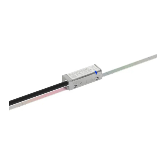
- Page 1 Installation guide M-9417-9238-03-A QUANTiC RKLC40-S incremental linear encoder system ™...
-
Page 2: Table Of Contents
QUANTiC quick-start guide Readhead mounting and alignment System calibration Restoring factory defaults Switching Automatic Gain Control (AGC) on or off Troubleshooting Output signals Speed Electrical connections Output specifications General specifications RKLC40-S scale specifications Reference mark Limit switches QUANTiC RKLC40-S linear installation guide... -
Page 3: Legal Notices
Renishaw. including interference that may cause undesired operation. The user is cautioned that any changes or modifications not expressly approved by Renishaw plc or authorised Trade marks representative could void the user’s authority to operate the equipment. -
Page 4: Storage And Handling
Installation Operating Humidity Minimum bend radius RKLC40-S – 50 mm +70 °C +35 °C +70 °C −20 °C +10 °C 0 °C NOTE: During storage, ensure self-adhesive tape is on the outside of the bend. 95% relative humidity (non-condensing) to IEC 60068-2-78 QUANTiC RKLC40-S linear installation guide... -
Page 5: Quantic Readhead Installation Drawing
2 mounting holes M2.5 through, counterbored Ø3 × 2.3 deep both sides. NOTE: The recommended thread engagement is 5 min (7.5 including counterbore) and the recommended tightening torque is between 0.25 and 0.4 Nm. Extent of mounting faces. † Dimension from substrate. QUANTiC RKLC40-S linear installation guide... -
Page 6: Rklc40-S Scale Installation Drawing
NOTES: The reference mark selector and limit actuator locations are correct for the readhead orientation shown. External magnetic fields greater than 6 mT, in the vicinity of the readhead, may cause false activation of the limit and reference sensors. QUANTiC RKLC40-S linear installation guide... -
Page 7: Rklc40-S Scale Application
Appropriate cleaning solvents (‘Storage and handling’, page 2) 2 × M2.5 screws Guillotine (A-9589-0071) or shears (A-9589-0133) for cutting RKLC4S0-S to length required The reference mark selector magnet is only required for ‘Customer selectable reference mark’ readheads. QUANTiC RKLC40-S linear installation guide... - Page 8 Whilst holding the block in place, in a smooth motion, pull down the lever to cut through the scale. Guillotine press block orientation when cutting RKLC40-S scale Guillotine press block Hold the scale in place and close the shears in a smooth motion to cut through the scale. QUANTiC RKLC40-S linear installation guide...
- Page 9 Remove applicator carefully. Apply firm finger pressure via a clean lint-free cloth along the length of the scale after application to ensure complete adhesion. Clean the scale using Renishaw scale wipes or a clean, dry, lint-free cloth. NOTE: Scale applicator can be mounted either way round to enable easiest orientation for scale installation.
-
Page 10: End Clamps
End clamps The end clamp kit is designed to be used with Renishaw RKLC40-S scale. Alternative, narrow 6 mm wide end clamps (A-9523-4111), are also available. NOTE: End clamps can be mounted before or after readhead installation. The end clamp features two small regions of contact adhesive. These will temporarily hold the end Clean ends of scale and the area where end clamps are to be fitted using Renishaw scale wipes clamp in position while the adhesive cures. -
Page 11: Reference Mark Selector And Limit Magnet Installation
For more information refer to QUANTiC series encoder system data ™ sheet (Renishaw part no. L-9517-9778). External magnetic fields greater than 6 mT, in the vicinity of the readhead, may cause false activation of the limit and reference sensors. QUANTiC RKLC40-S linear installation guide... -
Page 12: Quantic Quick-Start Guide
13). Repeat the installation and calibration routine. * For more details refer to the Advanced Diagnostic Tool ADTi-100 and ADT View software User guide (Renishaw part no. M-6195-9413) and Advanced Diagnostic Tool ADTi-100 and ADT View software Quick-start guide (Renishaw part no. M-6195-9321). †... -
Page 13: Readhead Mounting And Alignment
AGC out of normal operating range Green Orange flashing (analogue flashing flashing flashing variant only) * ‘Troubleshooting’, page 14 for more information on diagnosing faults. Roll Pitch 0° ±0.8° 0° ±1° Green spacer Rideheight 2.1 ± 0.2 mm QUANTiC RKLC40-S linear installation guide... -
Page 14: System Calibration
To exit the calibration routine at any stage cycle the power to the readhead or connect the ‘Remote CAL’ output pin to 0 V for < 3 seconds. The LED will then stop flashing. Settings stored Blue single flashing None, restore factory defaults and recalibrate Blue double flashing Incremental only Blue (auto-complete) Incremental and reference mark QUANTiC RKLC40-S linear installation guide... -
Page 15: Restoring Factory Defaults
The AGC is automatically enabled once the system has been calibrated (indicated by a Blue LED). AGC can be manually switched off by connecting the ‘Remote CAL’ output pin to 0 V for > 3 seconds < 10 seconds. The LED will then be solid Green. NOTE: AGC can be switched on or off using the optional ADTi-100 and ADT View software. See www.renishaw.com/adt for more information. QUANTiC RKLC40-S linear installation guide... -
Page 16: Troubleshooting
Ensure you are moving the readhead past your chosen reference mark several times after moving it past the reference mark Check the readhead /selector magnet orientation several times Check the readhead optical window and scale are clean and free from contamination QUANTiC RKLC40-S linear installation guide... - Page 17 Check output signal termination (page 18) When using with ADTi-100 in stand-alone mode ensure Termination tool is connected, Renishaw part number A-6195-2132 Exit CAL mode and restore factory defaults (page 13) Check readhead set-up and alignment (page 11) QUANTiC RKLC40-S linear installation guide...
-
Page 18: Output Signals
Pack of 5 14-way JST SH mating sockets: Setup Clear A-9417-0024 - Bottom mount; Remote CAL * Orange A-9417-0026 - Side mount. Maximum of 20 insertion cycles for JST connector. Shield Screen Case Case Ferrule QUANTiC RKLC40-S linear installation guide... -
Page 19: Speed
4.53 0.91 0.45 0.18 0.091 0.045 1038 Analogue readheads Maximum speed: 20 m/s (−3dB) † * For a readhead with a 1 m cable. † If the speed exceeds 20 m/s, SDE performance cannot be guaranteed. QUANTiC RKLC40-S linear installation guide... -
Page 20: Electrical Connections
Digital Readhead cable Output signals Dependent on cable type, readhead cable length and Maximum extension clocked output option. Contact your local Renishaw cable length representative for more information. Shield Readhead to ADTi-100 IMPORTANT: The shield should be connected to the machine earth (Field Ground). -
Page 21: Output Specifications
Reference 0.8 to 1.2 Vpp NOTE: A wide reference mark option, outputting a reference pulse for the duration of the signal 45° period is available. Contact your local Renishaw † Bi-directionally repeatable. representative for more information. Differential pulse V centred on 45°. -
Page 22: General Specifications
Digital output < ±120 nm < ±80 nm CAUTION: Renishaw encoder systems have been designed to the relevant EMC standards, but must be correctly integrated to achieve EMC compliance. In particular, attention to shielding arrangements is essential. * To limit maximum tension in the scale (CTE −... -
Page 23: Rklc40-S Scale Specifications
3 mm before that edge Mounting Customer placed at desired locations Repeatability < 0.1 mm * The scale and end clamps must be installed following the installation process, see page 7 page QUANTiC RKLC40-S linear installation guide... - Page 24 New Mills, Wotton-under-Edge uk@renishaw.com Gloucestershire, GL12 8JR United Kingdom www.renishaw.com *M-9417-9238-03* For worldwide contact details, visit www.renishaw.com/contact Renishaw plc. Registered in England and Wales. Company no: 1106260. Part no.: M-9417-9238-03-A Registered office: New Mills, Wotton-under-Edge, Gloucestershire, GL12 8JR, UK. Issued: 12.2020...
Need help?
Do you have a question about the QUANTiC RKLC40-S and is the answer not in the manual?
Questions and answers