
Related Manuals for Renishaw RGH25F


Summary of Contents for Renishaw RGH25F
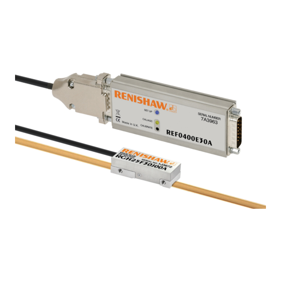
- Page 1 Installation guide M-9562-9063-02-A RGH25F RGS20 linear encoder system RSLM high accuracy linear encoder...
-
Page 2: Table Of Contents
Contents Product compliance Storage and handling RGH25F readhead installation drawing REF interface installation drawing RGS20 scale installation drawing Scale application End clamps Reference mark and limit switch actuator installation Readhead mounting and alignment System calibration Reference mark setup Limit switch... -
Page 3: Product Compliance
Recyclable received, including interference that may cause undesired operation. Cardboard Not applicable Recyclable The user is cautioned that any changes or modifications not expressly approved by Renishaw plc or Bags High Density Polyethylene Bag HDPE Recyclable authorised representative could void the user’s authority to operate the equipment. -
Page 4: Storage And Handling
Minimum bend radius RGS20 – 100 mm NOTE: Ensure self-adhesive tape is on outside of bend. System Storage Operating Humidity System System 95% relative humidity +70 °C +55 °C (non-condensing) -20 °C 0 °C to EN 60068-2-78 RGH25F RGS20 installation guide... -
Page 5: Rgh25F Readhead Installation Drawing
RGH25F readhead installation drawing Dimensions and tolerances in mm -0.1 Arrow indicates forward direction Fixing screws +0.2 of readhead relative to scale M3 x 0.5 x 8 † See note 11.5 Alternative 6 (RGS20-S) mounting face 6.3 (RGS20-P) 13.5 Mounting face (Yaw tol. -
Page 6: Ref Interface Installation Drawing
NOTE: Remove washers when installing brackets Max. screw size M4 19.2 33.3 Set up LED Output 15 way Calibrate button D type plug Input 15 way CAL /AGC LED D type socket 0.35 Nm torque 16.2 RGH25F RGS20 installation guide... -
Page 7: Rgs20 Scale Installation Drawing
Overall length (ML + 70) NOTE: The surface roughness of the scale mounting surface must be ≤3.2 Ra. The parallelism of the scale surface to the axis of motion (readhead rideheight variation) must be within 0.05 mm. RGH25F RGS20 installation guide... -
Page 8: Scale Application
Scale application End clamps The scale applicator A-9541-0124 is designed specifically for use with the RGH25F readheads A-9523-4015 is an end clamp kit designed to be used with Renishaw RGS scale. and RGS20-S scale. Use applicator A-9541-0305 when installing RGS20-P scale. -
Page 9: Readhead Mounting And Alignment
For easier installation, adjust the roll and yaw of the bracket with respect to the axis of readhead REF Interface LED diagnostics travel before the RGH25F is attached. This can be done with a clock gauge and a precision square. The REF interface SETUP LED provides visual feedback of signal strength, error condition and reference Readhead set-up mark phasing, for setup and diagnostic use. -
Page 10: Reference Mark Setup
100 mm/s traverse speed. Limit switch A limit switch signal is output when the readhead sensor passes over the magnetic actuator. NOTE: RGH25F readheads are available with reference mark or limit switch detection. Select output at order. RGH25F RGS20 installation guide... -
Page 11: Output Signals
Z+ / Q+ + / V Interpolation factor (period to resolution) Reference mark Pink Hall / limit Z- / Q- - / V – – Analogue system - RGH25F + REF0000 Alarm – – – – – Ired servo Brown Servo –... -
Page 12: Electrical Connections
NOTE: Maximum extension cable length: The inner shield should be connected to 0 V at customer electronics only. Care should be RGH25F and REF interface - analogue output (REF0000) - 100 m taken to ensure that the inner and outer shields are insulated from each other. If the inner... -
Page 13: Output Specifications
Inverse signals not shown for clarity † Limit Repeatability <0.1 mm typical Length of actuating magnet Asynchronous pulse Q NOTE: RGH25F readheads and REF interfaces are available with reference mark or limit switch detection. Actuation device A-9541-0040/A-9531-0251 RGH25F RGS20 installation guide... - Page 14 Actuation device A-9541-0037/A-9559-0650 Limit Repeatability <0.1 mm typical +) - (V Length of actuating magnet Asynchronous pulse V NOTE: RGH25F readheads and REF interfaces are available with reference mark or limit switch detection Actuation device A-9541-0040/A-9531-0251 RGH25F RGS20 installation guide...
-
Page 15: General Specifications
-10 °C to +120 °C. Minimum installation 10 °C Renishaw encoder systems have been designed to the relevant EMC standards, but must be Storage -20 °C to +70 °C. correctly integrated to achieve EMC compliance. In particular, attention to shielding arrangements is essential. - Page 16 RENISHAW ® and the probe symbol used in the RENISHAW logo are registered trade marks of Renishaw plc in the United Kingdom and other countries. *M-9562-9063-02* apply innovation and names and designations of other Renishaw products and technologies are trade marks of Renishaw plc or its subsidiaries.
Need help?
Do you have a question about the RGH25F and is the answer not in the manual?
Questions and answers