
Subscribe to Our Youtube Channel
Summary of Contents for Setra Systems MicroCal
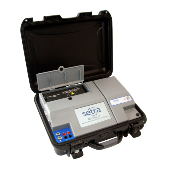
- Page 1 User Manual MicroCal ™ Advanced Modular Pressure Calibrator 800.257.3872 setra.com...
-
Page 3: Table Of Contents
5.1 USER INTERFACE PANEL..............11 5.2 BATTERY CHARGING................11 5.3 REPLACE & INSTALL BATTERY..............12 5.4 REFERENCE INSTALLATION..............14 5.5 GETTING STARTED................14 6.0 MICROCAL INTERFACE SCREENS 6.1 APPLICATION DEFINITIONS..............16 6.2 REAL TIME: GENERAL.................16 6.21 REAL TIME: DIAL GAUGE..............17 6.22 REAL TIME: P-SWITCH ..............17 6.23 REAL TIME: EXPERT SYSTEM............17 6.3 RUN TEST: GENERAL................18... - Page 4 7.0 UNIT UNDER TEST CONNECTION..............35 8.0 CALIBRATING/TESTING A TRANSDUCER/TRANSMITTER .........35 9.0 MICROCAL MANAGER INTERFACE 9.1 SETUP FOR MICROCAL CONNECTION ..........38 9.2 GRAPHICAL USER INTERFACE SETUP ..........39 9.3 TEST RESULTS DATA ................43 10.0 MICROCAL SPECIFICATIONS 10.1 MEASUREMENT................46 10.2 CONTROL..................46 10.3 GENERAL SPECIFICATIONS...............46 11.0 ADDITIONAL RESOURCES...
-
Page 5: Safety Instructions
1.0 SAFETY INSTRUCTIONS Use the calibrator only as specified in the manual, otherwise the protection provided may be impaired. Do not operate the calibrator in explosive gas, vapor or dust environments. The calibrator is designed to operate from 14.4 VDC removable Lithium Ion battery source or from the AC adaptor that is included. -
Page 6: Introduction
The design of the MicroCal exploits years of experience in the calibration of Setra trans- ducers, as well as NASA patented and Setra exclusive licensed technology. -
Page 7: Standard Equipment Breakout
3.0 STANDARD EQUIPMENT BREAKOUT THE ITEMS BELOW ARE INCLUDED IN YOUR CALIBRATOR: Calibration Certificate Diagram 2 Calibrator User Manual Electronic Test Lead Kit Rechargeable Battery Pneumatic Fittings & Tubing AC Power Adapter Accessory Box Pressure Module Box What’s Included: What’s Included: User Manual Up to 4 Pressure Reference Rechargeable Battery... -
Page 8: Operating Features
4.0 OPERATING FEATURES 4.1 THE MICROCAL PERFORMS THE FOLLOWING MAJOR FUNCTIONS • User interface for setups, display and storage. • Data transfer to and from MicroCal Manager Database. • Monitors battery voltage • Stores data for UUT, test profiles and test results. -
Page 9: Calibrator Screen Overview
4.3 CALIBRATOR SCREEN OVERVIEW Real-Time Screen • Displays installed references • Actively read Applied Pressure, UUT Output & % Error • Apply user selectable pressure, for manual cali- bration • Enable either Control (apply pressure) or Monitor (read pressure from system) •... - Page 10 • The UUT setup/selection is utilized across multiple screen functions System Screen • Communications software revisions of the MicroCal • Visual indication of battery level • Set default settings for the unit • Select engineering units to be used across all...
-
Page 11: Calibrator Setup
Diagram 4 5.2 BATTERY CHARGING The MicroCal is assembled, calibrated and tested at the factory. The battery, as received, will be in a partially charged state. Before operation please be sure to fully charge the battery to get maximum portable use of the device. -
Page 12: Replace & Install Battery
5.3 REPLACE & INSTALL BATTERY Open Battery Door: Rotate the black knob counter-clockwise and pull up on the battery door. Remove Installed Battery: Pull tab and lift out battery. Install Charged Battery: Align pins inside the battery compartment with the receptacle on charged battery. -
Page 13: Reference Installation
5.4 REFERENCE INSTALLATION: CHANGING MICROCAL PRESSURE MODULE (MCPM) (Diagram 6) The MicroCal is designed with 2 pressure reference bases. These MCPM reference mod- ules can be added in field into either base. Software will automatically detect installed reference. Open Reference Door (See Diagram 6): Rotate the black knob counterclockwise and pull up on the reference door. -
Page 14: Getting Started
5.5 GETTING STARTED 1. Open calibrator top. 2. Turn on calibrator power by toggling the power button towards the back of the unit (power switch on left side of the calibrator see Diagram 7). 3. Once calibrator is powered up, re-zero function begins automatically. Please wait for completion. - Page 15 Go to Pressure Enable Monitor Only Macro Buttons Mode ( No Pressure Control) Enables Pressure Installed Control Pressure References TARES Internal Pressure Standards Applied Snapshot of Data Pressure Vents Pressure to Atmosphere Access Stored UUT Profiles Output Excitation to Unit Under Test Terminal Bar Graph of Error...
-
Page 16: Microcal Interface Screens
6.0 MICROCAL INTERFACE SCREENS The MicroCal Interface is tab-based, split into 5 major sections at the bottom of the screen. 6.1 APPLICATION DEFINITIONS General: This describes operation for the broadest range of applications. Dial Gauge: Departures from general operation for Dial Gauge calibration. -
Page 17: Real Time: Dial Gauge
Enable Monitor Only Mode ( No Pressure Go to Pressure Enables Pressure Control) Macro Buttons Control Installed Pressure References TARES Internal Pressure Standards Stops Pressure Control Applied Pressure Vents Pressure to Atmosphere Access Stored UUT Profiles Output Excitation to Unit Under Test Terminal Error Graph... -
Page 18: Run Test: General
6.3 RUN TEST: GENERAL Screen Instructions (Diagram 10): 1. Tap the RUN TEST tab at the bottom of the page. 2. Select desired UUT from the drop down box at the top of the page. If desired UUT is not there, see Page 24 for creating a new UUT. -
Page 19: Run Test: Dial Gauge
Diagram 11 6.31 RUN TEST: Dial Gauge Differences from General (Diagrams 10 & 11): -Pressing RUN button brings up separate test page with dither control (Diagram 12). -Output columns removed from Test Profile/Results window. 6.32 RUN TEST: P-SWITCH Differences from General (Diagrams 10 & 11): -Pressing RUN button brings up separate test page with dither control (Diagram 12). -
Page 20: Run Test: Dither Control Page
Target Pressure Button: Set pressure target to original target defined by test profile for present test point. Vent Button: Stops the test in progress and vents MicroCal pressure ports to atmosphere. Halt: Pauses pressure control. Leaves system closed to allow for quick re-acquisition of target pressure. -
Page 21: Run Test: Expert System
-Automatically performs recal if “As Found” data is found to be outside limits on UUT page -Performs recal maximum of three tries before flagging UUT as “No Recal” -Records successful recal “As Left” -Test data available as “As Found” and “As Left” data pair in MicroCal Manager Software. -
Page 22: Test Setup: General
6.4 TEST SETUP: GENERAL Setting up Test Profiles Database (Diagram 13): Profiles are pressure settings used during testing. Program has capability of creating additional test profiles besides the default test profiles that are installed. If a new profile setup is required tap the TEST SETUP tab. Select NEW button Type new TEST ID in box. -
Page 23: Test Setup: Dial Gauge
CREATE CUSTOM TEST SETUP This test setup page allows custom entry of target pressure, target output, or target % FS (Full Scale) to be stored for a test by selecting “Custom” from the PROFILE TYPE drop- down. To change, double click value in any field, and enter a new value. The remaining fields will update automatically. -
Page 24: Uut (Unit Under Test) Setup: General
6.5 UUT (UNIT UNDER TEST) SETUP: GENERAL Screen Instructions (Diagram 15): UUT setup screeen is used for inputing UUT profiles into the UUT database. Select an Existing Profile - Go to the UUT ID drop down box, click the down arrow and select your unit from the list. - Page 25 UUT Input/Output Specs (Ideal) UUT Type UUT ID Box New UUT ID Setup Profile Template ID to Copy From Save New UUT ID UUT Serial Number UUT Accuracy Delete UUT ID Accuracy Spec Where UUT Is Adjusted Excitation Diagram 15...
- Page 26 UUT PAGE (Page 2 of 2) Enter the UUT Part Number. Enter the UUT Model. Enter the UUT Manufacturer. Enter the required pressure Settling Time at target (in milliseconds, 99,999 max. and 0 min, 5,000 recommended.) Pressure settling time is time allowed at pressure point before data is acquired.
- Page 27 UUT Part Number Create New UUT Profile UUT Model Accept Changes UUT Manufacturer Settling Time for Data Acq. Delete UUT Profile Max. Leak Rate Allowable for Pass/Fail Adjust Pressure Control Sensitivity Pressure Stability Required for Data Acquisition Diagram 16...
-
Page 28: Uut Setup: Dial Gauge
6.51 UUT TYPE: DIAL GAUGE Differences from General (Diagram 15): -Output fields hidden. -Excitation field hidden. 6.52 UUT TYPE: P-SWITCH Differences from General (Diagram 15): -Output fields converted to Manual Reset check boxes. -Excitation field hidden. -LO/HI labels changed to OPEN/CLOSE. -Profile selection locked out. -
Page 29: Uut Setup: Expert System
6.53 UUT SETUP: EXPERT SYSTEM No Differences from General (See Section 6.5) -
Page 30: System
6.6 SYSTEM Screen Instructions (Diagram 18): Data and system values: Software Version - Version of software on MicroCal. Firmware Version - Version of firmware on calibrator microprocessor board. Serial Number - Serial number of device. Calibration Date - Date of last calibration. - Page 31 Software Version Filter Length Firmware Version Excitation Serial Number Battery Level System Volume Next Calibration Due Date Eng. Units Setting Default System Setting Diagram 18...
- Page 32 EDIT DEFAULTS PAGE DISPLAY TREND GRAPH ON UUT WARM-UP: will make a graph appear when the test page is opened, or the UUT ID is changed on test page. The graph will show UUT output vs. time to allow the operator to see if the UUT has a warm-up drift, and output has stabilized.
- Page 33 RE-CAL ACCURACY: Re-cal accuracy to be used when automatically setting up an AUTO-DETECT UUT. Note: This value is used to determine if the MicroCal should adjust the unit, despite a passing As Found test. DEFAULT ACCURACY: Accuracy to be used when automatically setting up an AUTO-DE- TECT UUT.
- Page 34 ENGINEERING UNITS SCREEN This page is used to convert the displayed engineering units on the MicroCal. All values are stored as a default in WC. Displayed values are then converted using conversion values below. Press to set units to Press to exit w/out...
-
Page 35: Unit Under Test Connection
7.0 UNIT UNDER TEST CONNECTION Standard - (See Diagram 22) Attach the unit in a secure location. Hook up the pneumatic lines - attaching the high port (HI) on the calibrator to the high port on the UUT and the low port (LO) on the calibrator to the low port on the UUT. Hook up electrical lines- (See Diagram 23 for wiring options) Diagram 22 Unit Under Test... -
Page 36: Calibrating/Testing A Transducer/Transmitter
8.0 CALIBRATING/TESTING A TRANSDUCER/TRANSMITTER MANUAL CALIBRATION (Typical): Select UUT Profile from either drop-down on real-time screen or by going to the UUT tab from real-time screen drop down or from UUT tab. Select UUT ID from list and verify. Select REAL TIME tab (If on UUT tab) Connect UUT according to UUT Connection Guide (See Section 7.0). -
Page 37: Microcal Manager Interface
2. Select “Auto-Detect” from UUT ID drop down box. Wait for software prompt to plug EPIC cable into Transducer. 3. Remove Process Head from pressure sensor and plug in EPIC connected to MicroCal top panel header. FIRST TIME UUT AUTO-DETECT -The MicroCal will automatically download and save a new UUT Profile from a Setra 269. -
Page 38: Setup For Microcal Connection
The MicroCal Provides a central location for all data within a given facility, database management and easy data entry and manipulation. 9.1 SETUP FOR PC CONNECTION 1. Connect MicroCal to PC via micro USB cable. 2. Verify device is connected on Windows Mobile Device Center. -
Page 39: Graphical User Interface Setup
DATA SETS UUT (Unit Under Test) Profiles - These define a transducer so the MicroCal knows what it’s working with. (See Diagram 26 - Portion outlined in red) Test Profiles - Determines how a test is performed. (See Diagram 26 - Portion outlined in blue) Test Results - Actual data files created when a test is recorded on the PC. - Page 40 (See Diagram 29) 1. To select a profile, simply click on the ID in the list. 2. Only one profile can be selected at a time from both PC and MicroCal database lists. Diagram 29...
- Page 41 I.E., if a profile is selected in the PC database, and Transfer -> button is pressed, the profile will now be copied to the MicroCal database. When transferring profiles, if a profile of the same ID exists in the ‘Copy To’ database, the profile will be overwritten on the ‘Copy To’...
- Page 42 New Button - This button opens a dialog box to create a unique profile. Profile ID must be entered into the ID box on the dialog. To copy a profile, simply highlight the desired profile within the list window, and then press NEW.
-
Page 43: Test Results Data
9.3 TEST RESULTS DATA At bottom of screen, there is a list box showing all the test results data files stored in memory. On connect, all the data files from the Pocket PC are copied to the main PC database. If a file already exists with the same name, the file will not be copied. - Page 44 Once a UUT ID is selected, the test results list will update to display only the test results from that UUT. (See Diagram 36) The test results for each UUT can be distinguished using date/time of test and As Left/As Found status.
- Page 45 This will bring up a printer selection dialog. Select printer from here and press ‘OK’ button. (See Diagram 38) Diagram 38 To print an As Left/As Found pair, the test results must be selected manually: Select ‘As Found’ file then, while holding CTRL key, select ‘As Left’ file. Press ‘Print’...
-
Page 46: Microcal Specifications
10.0 MICROCAL SPECIFICATIONS 10.1 MEASUREMENT UNCERTAINTY (1 YR) Pressure ±0.12% Reading ±0.028% FS Voltage ±0.015% Reading ±0.002 mV Current ±0.015% Reading ±0.002 mA Physical Operating Temperature to 95 F (10 to 35 Storage Temperature to 160 F (0 to 71... -
Page 47: Glossary Of Terms
11.0 ADDITIONAL RESOURCES 11.1 GLOSSARY OF TERMS Atmospheric Pressure - Pressure of the atmosphere at the Earth’s surface. NIST standard atmospheric pressure = 1.01325 bar. Burst Pressure - The maximum pressure that may be applied to the positive pressure port without rupturing the sensing element. -
Page 48: Interpreting Pressure Transducer Specifications
11.2 INTE PRESSURE TRANSDUCER SPECIFICATIONS Accuracy Expressed in %FS as constant temperature. Accuracy as RSS non-linearity, hysteresis and non-repeatability ROOM SUM SQUARES (RSS) NON-LINEARITY (±0.1%) 0.01% HYSTERESIS (±0.05%) 0.0025% NON-REPEATABILITY (±0.02%) 0.0004% 0.0129% √0.0129% ±0.11%FS at constant temperature Total Error Band (Worst Case) Over a Temperature Range of -10 F to 130 Non-Linearity:... - Page 49 Non-Repeatability The ability of a transducer to reproduce output readings when the same pressure value is applied to it consecutively, under the same conditions, and from the same direction. Hysteresis The maximum difference in output at any pressure value within the specified range, when the value is approached with increasing and decreasing pressure.
- Page 50 Zero Offset Zero output is factory set to within a certain % of full scale. Results in a shift up or down of the calibration curve. Does not affect linearity or accuracy. Span Offset Span output is factory set to within a certain % of full scale. Results in a change in the slope of the curve.
- Page 51 Non-Linearity Best Fit Straight Line (BFSL) Method: Relationship of a calibration curve to a specified straight line. Example: ±0.1% FS End Point Method: Relationship of a calibration curve to a specified straight line through its end points. Example: ±0.05% FS Terminal Method: Relationship of a calibration curve to a specified straight line with end points at zero and full scale.
-
Page 52: Spare Parts & Accessories
12.0 SPARE PARTS & ACCESSORIES Part # Item 869973-G Spare Battery 869974-G Desktop Charger 869923 Accessory Kit (Screwdriver, Silicon Tube, Misc. Fittings) 869920 Harness Cable End Ass’y, 2-Wire 869904-10 2-Wire Electro-Pneumatic Harness: 10 ft. 869921 Harness Cable End Ass’y, 4-Wire 869905-10 4-Wire Electro-pneumatic Harness: 10 ft. -
Page 53: Recalibration & Warranty Information
Calibration Services: Setra maintains a complete calibration facility that is traceable to the National Institute of Standards & Technology (NIST). Setra warrants its Model MicroCal to the original consumer purchaser against defects for a period of one year from the date of sale by SETRA, as shown in its shipping documents.
Need help?
Do you have a question about the MicroCal and is the answer not in the manual?
Questions and answers