
Related Manuals for Johnson Pump SPX Flow CombiLineBloc


Summary of Contents for Johnson Pump SPX Flow CombiLineBloc
- Page 1 INSTRUCTION MANUAL CombiLineBloc In-line circulation pump in block execution Orginal instructions CLB/EN (1901) 6.6 Read and understand this manual prior to operating or servicing this product...
- Page 3 EC Declaration of conformity (Directive 2006/42/EC, appendix II-A) Manufacturer SPX Flow Technology Assen B.V. Dr. A.F. Philipsweg 51 9403 AD Assen The Netherlands hereby declares that all pumps member of productfamilies CombiBloc, CombiBlocHorti, CombiChem, CombiLine, CombiLineBloc and CombiNorm whether delivered without drive (last position of serial number = B), or delivered as an assembly with drive (last position of serial number = A), are in conformity with the provisions of Directive 2006/ 42/EC (as altered most recently) and where applicable the following directives and...
- Page 4 Declaration of incorporation (Directive 2006/42/EC, appendix II-B) Manufacturer SPX Flow Technology Assen B.V. Dr. A.F. Philipsweg 51 9403 AD Assen The Netherlands hereby declares that the partly completed pump (Back-Pull-Out unit), member of productfamilies CombiBloc, CombiBlocHorti, CombiChem, CombiLine, CombiLineBloc and CombiNorm is in conformity with the following standards: •...
- Page 5 Instruction manual All technical and technological information in this manual as well as possible drawings made available by us remain our property and shall not be used (otherwise than for the operation of this pump), copied, duplicated, made available to or brought to the notice of third parties without our prior written consent.
- Page 6 INT/EN (1512) 1.2...
-
Page 7: Table Of Contents
CombiLineBloc Table of Contents Introduction Preface Safety Guarantee Inspection of delivered items Instructions for transport and storage 1.5.1 Weight 1.5.2 Use of pallets 1.5.3 Hoisting 1.5.4 Opening the packaging 1.5.5 Storage Ordering parts General Pump description Applications Type code Serial number Bearing groups Construction 2.6.1... - Page 8 Installation Connecting the electric motor Commissioning Inspection of the pump Inspection of the motor Preparing the pump unit for commissioning Checking the sense of rotation Pump in operation Noise Maintenance Daily maintenance Mechanical seal Lubrication of the bearings Environmental influences Noise Motor Faults...
- Page 9 CombiLineBloc CLB parts 9.2.1 Sectional drawing 9.2.2 Parts list Additional parts 200-160 Base plate Technical data 10.1 Recommended locking liquids 10.2 Tightening moments 10.2.1 Tightening moments for bolts and nuts 10.2.2 Tightening moments for cap nut 10.3 Hydraulic performance 10.3.1 Performance overview 10.4 Noise data...
- Page 10 CLB/EN (1901) 6.6...
-
Page 11: Introduction
CombiLineBloc 1 Introduction Preface This manual is intended for technicians and maintenance staff and for those who are in charge of ordering spare parts. This manual contains important and useful information for the proper operation and maintenance of this pump. It also contains important instructions to prevent potential accidents and damage, and to ensure safe and fault-free operation of this pump. -
Page 12: Guarantee
Guarantee SPXFLOW shall not be bound to any guarantee other than the guarantee accepted by SPXFLOW. In particular, SPXFLOW will not assume any liability for explicit and/or implicit guarantees such as but not limited to the marketability and/or suitability of the products supplied. -
Page 13: Hoisting
CombiLineBloc 1.5.3 Hoisting When lifting a complete pump unit always use a proper and sound lifting device, approved to bear the total weight of the load! Never go underneath a load that is being lifted! If the electric motor is provided with a lifting eye, this lifting eye is intended only for the purpose of carrying out service activities to the electric motor! The lifting eye is designed to bear the weight of the electric motor only! It is NOT permitted to lift a complete pump unit at the lifting eye of an electric... - Page 14 Introduction CLB/EN (1901) 6.6...
-
Page 15: General
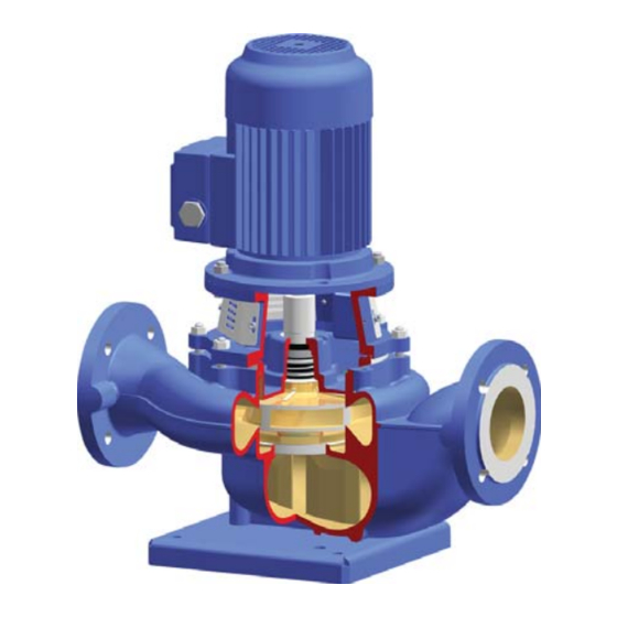
CombiLineBloc 2 General Pump description The CombiLineBloc is a built-in circulation pump constructed with a lantern piece and a standard IEC electric motor with flange. That means that the medium to be pumped will not get into the electric motor. The pump is provided with a mechanical seal with bellows mounted on the stub shaft which is mounted directly on the motor shaft. -
Page 16: Type Code
Type code Pumps are available in various designs. The main characteristics of the pump are shown in the type code. Example: CLB 65-200 G1 Pump family CombiLineBloc Pump size diameter discharge connection [mm] nominal impeller diameter [mm] Pump casing material cast iron bronze Impeller material... -
Page 17: Construction
CombiLineBloc Construction 2.6.1 Design The design is characterized by a compact construction. The pump is mounted to a standard IEC flange motor by means of a lantern piece and a stub shaft. The pump cover is clamped between the pump casing and the lantern piece. The electric motors up to and including frame size 112M have B5 mounting arrangement and the larger types have B3/B5 mounting arrangement. -
Page 18: Ecodesign Minimum Efficiency Requirements Water Pumps
Ecodesign Minimum Efficiency Requirements Water Pumps • Directive 2005/32/EC of the European Parliament and of the Council; • Commission regulation (EU) No 547/2012 Implementing Directive 2009/125/EC of the European Parliament and of the Council with regard to ecodesign requirements for water pumps. - Page 19 CombiLineBloc ‘Submersible multistage water pump’ (MSS) means a multistage (i > 1) rotodynamic water pump with a nominal outer diameter of 4” (10,16 cm) or 6” (15,24 cm) designed to be operated in a borehole at nominal speed of 2900 rpm, at operating temperatures within a range of 0°C and 90°C;...
- Page 20 Criterion A is the pass-or-fail minimum efficiency requirement at the best efficiency point (BEP) of the pump: η ≥ η Pump BOTTOM Where × ------------------- 0.75 Criterion B is the pass-or-fail minimum efficiency requirement at part load (PL) and at overload (OL) of the pump: η...
-
Page 21: Energy Efficient Pump Selection
CombiLineBloc 2.7.3 Energy Efficient Pump Selection In selecting the pump, care should be taken to ensure that the duty point required is as close as possible to the pump’s Best Efficiency Point (BEP). Different heads and flows can be achieved by changing the diameter of the impeller and thereby eliminating unnecessary energy loss. -
Page 22: Scope Of Implementing Directive 2009/125/Ec
Fitted impeller diameter Figure 4: Name plate horticulture MEI ≥ Ø eff. CR Nr. 04029567 Johnson Pump Horticulture De Hondert Margen 23 NL-2678 AC De Lier Table 3: Name plate horticulture CLB 65-200 G1 Product type and size 19-001160 Year and serial number 0,40 Minimum Efficiency Index at max. - Page 23 CombiLineBloc Figure 5: Name plate ATEX certified - www.johnson-pump.com SPX Flow Technology Assen B.V. Dr. A.F. Philipsweg 51, NL-9403 AD Assen - CR Nr. 04029567 Type: Ø MEI ≥ Code: eff. No.: Table 4: Name plate ATEX certified CLB 65-200 Product type and size Smartcode 19-001160...
- Page 24 The Netherlands Location Horticulture: SPX Flow Technology Assen B.V. Registration number at Chamber of Commerce 04 029567 Johnson Pump Horticulture De Hondert Margen 23 2678 AC De Lier The Netherlands 5 Product type and size identifier are marked on the rating plate. An example and explanation is given in paragraph 2.7.5 "Product information"...
-
Page 25: Application Area
CombiLineBloc 9 The operation of this water pump with variable duty points may be more efficient and economic when controlled, for example, by the use of a variable speed drive that matches the pump duty to the system. 10 Information relevant for disassembly, recycling or disposal at end-of-life is described in paragraph 2.9 "Re-use", paragraph 2.10 "Scrapping"... - Page 26 General CLB/EN (1901) 6.6...
-
Page 27: Installation
CombiLineBloc 3 Installation Safety • Read this manual carefully prior to installation and commissioning. Non-observance of these instructions can result in serious damage to the pump and this will not be covered under the terms of our guarantee. Follow the instructions given step by step. •... -
Page 28: Piping
Piping As regards the piping and connecting points of the pump attention should be paid to the following: • Preferably the pump should be mounted in the piping in such a way that the direction of flow is vertical, so as to prevent air from remaining in the pump. Air in the pump may cause damage to the mechanical seal! •... -
Page 29: Commissioning
CombiLineBloc 4 Commissioning Inspection of the pump • Check whether the pump shaft turns freely. Do this by turning the stub shaft a few times by hand. Inspection of the motor • Check whether the fuses have been mounted. Preparing the pump unit for commissioning Proceed as follows, both when the unit is put into operation for the first time and after the pump has been overhauled: 1 Open the valves. -
Page 30: Pump In Operation
Pump in operation When the pump is in operation, pay attention to the following: • The pump should never run dry. • Never use a stop valve in the suction line to control pump output. The stop valve should always be fully opened during operation. •... -
Page 31: Maintenance
CombiLineBloc 5 Maintenance Daily maintenance Regularly check the outlet pressure. No water should get into the terminal box of the electric motor when the pump room is sprayed clean! Never spray water on hot pump parts! The sudden cooling down may cause them to burst and hot water may flow out! Flawed maintenance will result in shorter lifespan, possible break down and in any event loss of warranty. -
Page 32: Faults
Faults 1 If the pump shows problems, the cause may be elsewhere in the system. First check whether this is the case. 2 If you are sure the problem is within the pump, try to determine the cause. See chapter 6 "Problem solving". Then take the necessary measures. 3 See chapter 7 "Disassembly and assembly"... -
Page 33: Problem Solving
CombiLineBloc 6 Problem solving Faults in a pump installation can have various causes. The fault may not be in the pump, it may also be caused by the pipe system or the operating conditions. Firstly, always check that installation has been executed in accordance with the instructions in this manual and that the operating conditions still correspond with the specifications for which the pump was purchased. - Page 34 Table 8: Possible causes of pump failures. Possible causes Pump or suction pipe is not sufficiently filled or de-aerated Gas or air coming from the liquid Air lock in the suction pipe Air leak in the suction pipe The manometric suction head is too high Suction pipe or suction strainer is blocked Insufficient immersion of foot valve or suction pipe during operation of the pump NPSH available too low...
-
Page 35: Disassembly And Assembly
CombiLineBloc 7 Disassembly and assembly Precautions Before the pump can be repaired it first has to be removed from the system. Take the following steps: 7.1.1 Switch off the electricity supply 1 Disconnect the electricity supply to the pump by setting the pump switch on the switchboard or, if available, the operation switch, to "O". -
Page 36: Disassembly
Disassembly 7.3.1 Disassembling the Back-Pull-Out unit NEVER start dismantling by loosening the motor bolts (0850) and nuts (0900). This may result in irrepairable damage to the mechanical seal and the impeller! 1 Loosen the fastening nuts (0810) of the lantern piece, see figure 6. If the pump is still in the piping, start from the bottom side and proceed along the two sides upward, see figure 7. -
Page 37: Impeller
CombiLineBloc Impeller 7.4.1 Disassembling the impeller Figure 8: Disassembling the impeller. The item numbers used are referring to figure 8. 1 Remove the Back-Pull-Out unit, see paragraph 7.3.1 "Disassembling the Back-Pull- Out unit". 2 Block the impeller (0120) against rotating, see figure 9. 4002 Figure 9: Loosening the impeller nut. -
Page 38: Mounting The Impeller
7.4.2 Mounting the impeller 200-160 only: 1 Fit the rotating part of the mechanical seal on the stub shaft. 2 Fit the shaft sleeve (1200) and set the distance to the shaft collar to 44 mm. See figure 12 of paragraph 7.5.3 "Assembling a mechanical seal M1". Tighten the set screws (1260). -
Page 39: Mechanical Seal
CombiLineBloc Mechanical seal 7.5.1 Instructions for mounting a mechanical seal ➢ First read the following instructions regarding the mounting of a mechanical seal. Follow these instructions closely when mounting a mechanical seal. • Leave the assembly of a mechanical seal with PTFE (Teflon) covered O- rings to a specialist. -
Page 40: Disassembling A Mechanical Seal M1
7.5.2 Disassembling a mechanical seal M1 2200 1100 1220 0110 0250 Figure 11: Mechanical seal M1. The item numbers used are referring to figure 11. 1 Remove the impeller, see paragraph 7.4.1 "Disassembling the impeller". 2 Pump size 200-160 only: Loosen the set screws (1260). See figure 12. 3 Pull the distance sleeve (1100) (Pump size 200-160: spacer sleeve (1200)) and the rotating part of the mechanical seal (1220) off the shaft. -
Page 41: Assembling A Mechanical Seal M1
CombiLineBloc 7.5.3 Assembling a mechanical seal M1 1 Make sure the stub shaft (2200) is not damaged. If it is, replace it. 2 Place the electric motor with the shaft upright. 3 Put the pump cover flat down and press the counter-ring of the seal straight into it. If necessary, use a plastic pressure piece. -
Page 42: Replacing The Stub Shaft And The Motor
Replacing the stub shaft and the motor 7.6.1 Disassembling the stub shaft and the motor Figure 13: Assembly of the stub shaft The item numbers used are referring to figure 13. 1 Dismantle the impeller and the shaft seal. See paragraph 7.4.1 "Disassembling the impeller"... -
Page 43: Assembling The Stub Shaft And The Motor
CombiLineBloc 7.6.2 Assembling the stub shaft and the motor 1 For electric motors with IEC-size 80 upto and including 112M: Remove the key (2210) from the motor shaft. 2 Put the motor in vertical position, shaft end up. Fit the stub shaft (2200) on the motor shaft. - Page 44 Disassembly and assembly CLB/EN (1901) 6.6...
-
Page 45: Dimensions
CombiLineBloc 8 Dimensions Dimensions drawings S x O T Figure 14: Pump dimensions drawing. Dimensions CLB/EN (1901) 6.6... -
Page 46: Pump Dimensions
Pump dimensions See figure 14. J1 J2 ND10 40C-125 40 345 250 125 125 100 79 96 85 75,5 M16 G1/4 G1/8 40-160 40 415 320 160 160 100 77 20 114 105 91 72,5 118,5 M16 G1/4 G1/8 40-200 40 455 360 180 180 100 77 20 138 129 93,5 105 124 M16 G1/4 G1/8... -
Page 47: Overall Length (G)
CombiLineBloc Overall length (G) Motor 80 90S/L 100L/112M 132S/M 160M/L 180M/L 200L 225S/M 250M 280S/M 40C-125 519 565 40-160 516 562 40-200 516 562 50-125 526 572 50-160 530 576 50-200 528 574 65-125 557 603 65-160 549 595 65-200 566 612 1094 80-125 577 623 80-160 588 634... -
Page 48: Weight
Weight Weight [kg] excluding motor Motor 100L/ 112M 40C-125 40-160 40-200 50-125 50-160 50-200 65-125 65-160 65-200 80-125 80-160 80-200 100-160 100-200 80A-250 125-160 125C-200 100A-250 150-125 150-160 150-200 125A-250 150-250 200-160 200-200 Dimensions CLB/EN (1901) 6.6... -
Page 49: Flange Dimensions
CombiLineBloc Flange dimensions See figure 14. EN 1092-2 (DIN2531) PN 6 and ISO 7005 S x T 4 x 14 4 x 14 4 x 14 4 x 14 4 x 18 4 x 18 EN 1092-2 (DIN2532) PN 10 and ISO 7005 S x T 4 x 18 4 x 18... - Page 50 Dimensions CLB/EN (1901) 6.6...
-
Page 51: Parts
CombiLineBloc 9 Parts Ordering parts 9.1.1 Order form You can use the order form included in this manual for ordering parts. When ordering parts always quote the following data: 1 Your address. 2 The quantity, the item number and the description of the part. 3 The pump number. - Page 52 CLB parts 9.2.1 Sectional drawing 0320 0235 2410 0250 0276 0240 2415 0300 0300 0110 1100 1860 1820 0120 90S/L 100L 0350 112M 1220 0800 0810 2200 0850 0900 2280 2280 0100 0310 2405 2400 2405 132S/M 160M/L 90S/L 2400 180M/L 100L 200L...
- Page 53 CombiLineBloc 9.2.2 Parts list Materials Item Quantity Description 0100 pump casing cast iron bronze 0110 pump cover cast iron bronze 0120* impeller cast iron bronze bronze 0235 bolt stainless steel 0240 washer stainless steel 0250 lantern piece cast iron 0276 seal guard stainless steel 0300*...
- Page 54 Additional parts 200-160 Figure 17: Shaft sleeve of 200-160. Materials Item Quantity Description 1200 shaft sleeve brass 1260 set screw stainless steel Parts CLB/EN (1901) 6.6...
- Page 55 CombiLineBloc Base plate 0880 0410 Figure 18: Base plate. Materials Item Quantity Description 0410 base plate steel 0880 bolt steel Parts CLB/EN (1901) 6.6...
- Page 56 Parts CLB/EN (1901) 6.6...
- Page 57 CombiLineBloc 10 Technical data 10.1 Recommended locking liquids Table 9: Recommended locking liquids. Description Locking liquid cap nut (1820) Loctite 243 10.2 Tightening moments 10.2.1 Tightening moments for bolts and nuts Table 10: Tightening moments for bolts and nuts. Materials A2, A4 Thread Tightening moment [Nm]...
- Page 58 10.3 Hydraulic performance 10.3.1 Performance overview 100-200 40-200 50-200 65-200 80-200 40-160 50-160 65-160 80-160 100-160 50-125 65-125 80-125 40C-125 8 10 40 50 60 80 100 150 200 300 [m/h] Figure 19: Performance overview 3000 min 80A-250 100A-250 150-250 200-200 100-200 40-200...
- Page 59 CombiLineBloc 80A-250 100A-250 150-250 200-200 100-200 40-200 50-200 65-200 80-200 125C-200 150-200 40-160 200-160 50-160 65-160 80-160 100-160 125-160 150-160 50-125 65-125 80-125 40C-125 5 6 7 8 10 40 50 60 80 100 150 200 300 [m/h] Figure 21: Performance overview 1000 min 100-200 40-200...
- Page 60 80A-250 100A-250 150-250 200-200 100-200 40-200 50-200 65-200 80-200 125C-200 150-200 40-160 50-160 65-160 80-160 100-160 125-160 150-160 50-125 65-125 80-125 40C-125 5 6 7 8 10 40 50 60 80 100 150 200 300 400 550 [m/h] Figure 23: Performance overview 1800 min 80A-250 100A-250...
- Page 61 CombiLineBloc 10.4 Noise data 10.4.1 Pump noise as a function of pump power [dB(A)] P [kW] Figure 25: Noise level as function of pump power [kW] at 1450 min A = sound power level, B = sound pressure level. [dB(A)] P [kW] Figure 26: Noise level as function of pump power [kW] at 2900 min...
- Page 62 10.4.2 Noise level of entire pump unit L [dB] 9 10 11 12 13 14 15 16 17 18 19 20 |L1 - L2| [dB] Figure 27: Noise level of entire pump unit. In order to determine the total noise level of the entire pump unit, the noise level of the motor must be added to that of the pump.
- Page 63 CombiLineBloc Index Accessories ......25 Electricity supply Applications ......13 disconnecting .
- Page 64 Noise ......28, 29 Operational range ....56 Packaging opening .
- Page 65 Order form for spare parts FAX Nr. ADDRESS Your order will only be dealt with if this order form has been correctly completed and signed. Order date: Your order number: Pump type: Execution: Quantity Item. No. Part Article number pump Delivery address: Invoicing address: Ordered by:...
- Page 66 ORDFORM (1512) 3.3 EN...
- Page 67 CombiPrime H Horizontal self-priming centrifugal pump CombiLineBloc In-line circulation pump in block execution SPX Flow Technology Assen B.V. Dr. A. F. Philipsweg 51, 9403 AD Assen, THE NETHERLANDS Phone: + 31 (0) 592 37 67 67 Fax: + 31 (0) 592 37 67 60 E-Mail: johnson-pump.nl@spxflow.com www.spxflow.com/johnson-pump www.spxflow.com...
Need help?
Do you have a question about the SPX Flow CombiLineBloc and is the answer not in the manual?
Questions and answers