Table of Contents
Advertisement
Quick Links
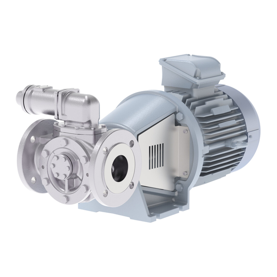
TopGear BLOC
I N T E R N A L G E A R P U M P S
A . 0 5 0 0 . 7 5 1 – I M - TG B LO C / 0 1 . 0 0 E N ( 1 0 / 2 0 2 0 )
O R I G I N A L I N S T R U CT I O N S
R E A D A N D U N D E R S TA N D T H I S M A N UA L P R I O R TO O P E R AT I N G O R S E R V I C I N G T H I S P R O D U CT.
I N S T R U CT I O N M A N UA L
Advertisement
Table of Contents

Subscribe to Our Youtube Channel
Related Manuals for Johnson Pump SPXFLOW TopGear BLOC Series


Summary of Contents for Johnson Pump SPXFLOW TopGear BLOC Series
- Page 1 I N S T R U CT I O N M A N UA L TopGear BLOC I N T E R N A L G E A R P U M P S O R I G I N A L I N S T R U CT I O N S A .
- Page 2 EC-Declaration of conformity Machinery Directive 2006/42/EC, Annex IIA Manufacturer SPX Flow Europe Limited Belgium Evenbroekveld 2-6 BE-9420 Erpe-Mere Belgium Herewith we declare that TopGear BLOC range Gear Pumps Types: TG BLOC15-50 TG BLOC23-65 TG BLOC58-80 TG BLOC86-100 whether delivered without drive or delivered as an assembly with drive, are in conformity with the relevant provisions of the Machinery Directive 2006/42/EC, Annex I.
-
Page 3: Table Of Contents
Contents Introduction ........................7 1.1 General ..........................7 1.2 Reception, handling and storage ................7 1.2.1 Reception ........................7 1.2.2 Handling ......................... 7 1.2.3 Storage .......................... 7 1.3 Safety ..........................8 1.3.1 General .......................... 8 1.3.2 Pump units ........................9 1.3.2.1 Pump unit handling ....................9 1.3.2.2 Installation ........................9 1.3.2.3... - Page 4 3.16.4 Sectional drawings and part lists ................24 3.16.4.1 Single safety relief valve ..................24 3.16.4.2 Heated spring casing .................... 25 3.16.4.3 Double safety relief valve ..................25 3.17 Installation ........................26 3.17.1 General ........................26 3.17.2 Location ........................26 3.17.2.1 Short suction line ....................26 3.17.2.2 Accessibility ......................
- Page 5 3.20.2.9 Fluid circuits ......................42 3.20.3 Specific components ....................42 3.20.3.1 Nuts and bolts ......................43 3.20.3.2 Plastic or rubber components ................43 3.20.3.3 Flat gaskets ......................43 3.20.3.4 Filter or suction strainer ..................43 3.20.3.5 Anti-friction bearings ..................... 43 3.20.3.6 Sleeve bearings ...................... 43 3.20.3.7 Shaft seal –...
- Page 6 6.2.1 TG BLOC15-50 to 86-100 ..................56 6.2.1.1 Cast iron ........................56 6.2.1.2 Stainless steel ......................57 6.3 Jackets (S) on pump cover and thread connection ........... 57 6.3.1 TG BLOC15-50 to 86-100 ..................57 6.4 Safety relief valves ..................... 58 6.4.1 Single safety relief valve ...................58 6.4.2 Double safety relief valve ..................58...
-
Page 7: Introduction
1.0 Introduction General This instruction manual contains necessary information on the TopGear pumps and must be read carefully before installation, service and maintenance. The manual must be kept easily accessible to the operator. Important! The pump must not be used for other purposes than recommended and quoted for without consulting your local supplier. -
Page 8: Safety
Safety 1.3.1 General Important! The pump must not be used for other purposes than recommended and quoted for without consulting your local supplier. A pump must always be installed and used in accordance with existing national and local sanitary and safety regulations and laws. •... -
Page 9: Pump Units
1.3.2 Pump units 1.3.2.1 Pump unit handling Use an overhead crane, forklift or other suitable lifting device. Secure lifting slings around the front Warning part of the pump and the back part of Never lift the pump unit with only the motor(If there are lifting rings on one fastening point. -
Page 10: Before Commissioning The Pump Unit
1.3.2.3 Before commissioning the pump unit Read the pump’s operating and safety manual. Make sure that the installation has been correctly carried out according to the relevant pump’s manual. Check the alignment of the pump and motor shafts. The alignment may have been altered during transport, lifting and mounting of the pump unit. -
Page 11: Technical Conventions
Technical conventions Quantity Symbol Unit Dynamic µ mPa · s = cP (Centipoise) viscosity ρ = density Kinematic ν = µ [kg] ρ dm viscosity ν = kinematic viscosity [ mm ] = cSt (Centistokes) Note! In this manual only dynamic viscosity is used. Pressure [bar] ∆p... -
Page 12: Pump Description
2.0 Pump description TopGear BLOC pumps are rotary positive displacement pumps with internal gear. They are made of cast iron or stainless steel. TG BLOC pumps are assembled from modular elements, which allows a variety of constructions: heating / cooling jackets (steam), several sleeve bearings, gear and shaft materials and mounted relief valve. - Page 13 Example TG BLOC 58-80 G2 S SG 2 G1 AV 8. Idler pin materials Idler pin in hardened steel Idler pin in nitrided stainless steel 9. Rotor and shaft materials Rotor in iron and shaft in steel Rotor in iron and shaft in nitrided stainless steell Rotor in stainless steel and shaft in nitrided stainless steell 10.
-
Page 14: General Technical Information
3.0 General technical information Pump standard parts Lantern piece Intermediate Pump shaft casing Top cover Idler pin Rotor Pump casing Pump cover Idler gear Operating principle As the rotor and idler gear unmesh, an underpressure is created and the liquid enters the new created cavities. Liquid is transported in sealed pockets to the discharge side. -
Page 15: Self-Priming Operation
3.2.1 Self-priming operation TopGear pumps are self-priming when sufficient liquid is present in the pump to fill up the clearances and the dead spaces between the teeth. (For self-priming operation see also section 3.17.6.2 Piping). 3.2.2 Safety relief valve – Working principle The positive displacement principle requires the installation of a safety relief valve protecting the pump against overpressure. -
Page 16: Main Characteristics
Main characteristics The pump size is designated by the displacement volume of 100 revolutions expressed in litres (or dm ) but rounded followed by the nominal port diameter expressed in millimetres. ∆p Vs-100 n.max n.mot Q.th Q.th p.test TG BLOC pump size (mm) (mm) (mm) -
Page 17: Pressure
Pressure Differential pressure or working pressure (p) is the pressure on which the pump normally operates. TopGear BLOC-line has the maximum differential pressure at 16 bar. (86-100 10 bar) The hydrostatic test pressure is 1.5 times the differential pressure i.e.: TopGear BLOC-line has the hydrostatic test pressure at 24 bar (86-100 15 bar). -
Page 18: The Sound Level Of The Pump Unit
3.7.2 The sound level of the pump unit The sound level of the drive (motor, transmission, . . .) must be added to the sound level of the pump itself to determine the total sound level of the pump unit. The sum of several sound levels must be calculated logarithmically. -
Page 19: Internals
3.10 Internals 3.10.1 Bush materials Overview of bush materials and application field Material Code Material Steel Carbon Bronze if yes to maximum working pressure = 16 bar Hydrodynamic lubrication if no 6 bar (*) 10 bar (*) 6 bar (*) Corrosive resistance Fair Good... -
Page 20: Mass Moment Of Inertia
3.11 Mass moment of inertia TG BLOC 15-50 23-65 58-80 86-100 J (10 x kg·m 3.12 Radial clearances TG BLOC 15-50 23-65 58-80 86-100 Minimum (µm) Maximum (µm) 3.13 Play between gear teeth TG BLOC 15-50 23-65 58-80 86-100 Minimum (µm) Maximum (µm) Play between gear teeth 3.14 Maximum size of solid particles... -
Page 21: Safety Relief Valve
3.16 Safety relief valve Example V 35 - G 10 H 1. Safety relief valve = V 2. Type indicating = inlet diameter (in mm) 27 Safety relief valve size for TG BLOC15-50, TG BLOC23-65 35 Safety relief valve size for TG BLOC58-80 50 Safety relief valve size for TG BLOC86-100... -
Page 22: Pressure
3.16.1 Pressure Safety relief valves are divided into 3 working pressure classes i.e. 4, 6 and 10 indicating the maximum working pressure for that valve. Each class has a standard set pressure at 1 bar above the indicated maximum working pressure. The set pressure can be set lower on request never higher. Working pressure class Standard set pressure (bar) Working pressure range (bar) - Page 23 Spring ratio – Safety relief valve Spring dimensions ∆H [mm] in order TG BLOC Pump size Pressure to adjust by class bar/mm 1 bar 37.0 0.21 4,76 15-50 37.0 0.21 4,76 23-65 36.5 0.81 1,23 49.0 0.32 3,13 58-80 49.0 0.32 3,13 48.6...
-
Page 24: Sectional Drawings And Part Lists
3.16.4 Sectional drawings and part lists 3.16.4.1 Single safety relief valve 7030 7400 7240 7050 7320 7150 7010 7100 7110 7310 7180 7330 7300 7170 7040 7360 Single safety relief valve – horizontal 7400 7310 7050 7180 Pos. Description Preventive Overhaul 7010 Valve... -
Page 25: Heated Spring Casing
3.16.4.2 Heated spring casing 7041 Pos. Description Preventive Overhaul 7041 Heated spring casing 3.16.4.3 Double safety relief valve 8020 8050 8020 8050 8010 8010 8070 8060 8070 8040 8060 8030 8040 8030 Double safety relief valve – horizontal Double safety relief valve – vertical Pos. -
Page 26: Installation
3.17 Installation 3.17.1 General This manual gives basic instructions which are to be observed during installation of the pump. It is therefore important that this manual is read by the responsible personnel prior to assembly and afterward to be kept available at the installation site. The instructions contain useful and important information allowing the pump/pump unit to be properly installed. -
Page 27: Indoor Installation
3.17.2.4 Indoor installation Locate the pump so that the motor can be vented properly. Prepare the motor for operation according to instructions provided by the motor manufacturer. When flammable or explosive products are pumped, a proper earthing should be provided. The components of the unit should be connected with earthing bridges to reduce the danger arising from static electricity. -
Page 28: Shaft Rotation For Pump Without Safety Relief Valve
3.17.4 Shaft rotation for pump without safety relief valve The shaft rotation determines which port of the pump is suction and which is discharge. The relation between the shaft rotation and the suction/discharge side is indicated by the rotation arrow plate attached at the top cover of a pump without safety relief valve. 1. - Page 29 The small arrows 2 and 3 indicate the flow direction of the pumped liquid. Always make sure that shaft rotation corresponds with the position of the discharge and suction ports and the direction indicated by the rotation arrow plate. If the shaft rotation is correct in relation to the port position but different from the direction indicated by rotation arrow plate, the safety relief valve must be disassembled and turned around by 180°.
-
Page 30: Suction And Discharge Pipes
3.17.6 Suction and discharge pipes 3.17.6.1 Forces and moments Note! Excessive forces and moments on the nozzle flanges derived from piping can cause mechanical damage to pump or pump unit. Pipes should therefore be connected in line, limiting the forces on the pump connections. Support the pipes and make sure they remain stress-free during operation of the pump. -
Page 31: Isolating Valves
Self-priming operation At the start sufficient liquid must be available in the pump filling up the internal clearance volume and the dead spaces, allowing the pump to build up a pressure difference. Therefore, for pumping low viscosity fluids, a foot valve with the same or larger diameter than the suction pipe must be installed or the pump can be installed without foot-valve but in U-line. -
Page 32: Heating Jackets
3.17.7.2 Heating jackets 1. S-type jackets The S-jackets are designed for use with saturated steam (max 10 bar, 180°C) or with non-dangerous media. They are provided with threaded connections Bl (see chapter 6.0 for the dimensions). The connection can be done by threaded pipes or pipe connections with sealing in the thread (conical thread applying ISO 7/1) or sealed outside the thread by means of flat gaskets (cylindrical thread applying ISO 228/1). -
Page 33: Guidelines For Assembly
3.17.9 Guidelines for assembly When a bare shaft pump is delivered, the assembly with drive is the responsibility of the user. The user also must provide all necessary devices and equipment allowing a safe installation and commissioning of the pump. 3.17.9.1 Transport of pump unit •... - Page 34 Electrical equipment, terminals and components of control systems may still carry live current when at rest. Contact with these may be fatal, resulting in serious injury or cause irreparable material damage. Line Motor U 1 V 1 W 1 U 1 V 1 W 1 U (volt) 230/400 V 400 V...
-
Page 35: Instructions For Start-Up
3.18 Instructions for start-up 3.18.1 General The pump can be put into service when all arrangements described in chapter 3.17 Installation have been made. • Prior to commissioning, responsible operators have to be fully informed on proper operation of the pump/pump unit and the safety instructions. This instruction manual must at all times be available to the personnel. -
Page 36: Checklist - Initial Start-Up
3.18.4 Checklist – Initial start-up After thorough servicing or when the pump is to be put into service for the first time (initial start-up) the following checklist must be observed: Supply and discharge line c Suction and discharge pipes are cleaned. c Suction and discharge pipes are checked for leaks. -
Page 37: Start-Up
3.18.5 Start-up When the pump is to be put into service the following checklist and procedure must be observed: c Pump is filled with liquid. c Pump is sufficiently preheated. c Suction and discharge valves are fully open. c Start the pump for a short while and check the direction of rotation of the motor. c Start the pump and check suction of liquid (suction pressure). -
Page 38: Trouble Shooting
3.19 Trouble shooting Symptom Cause Remedy No flow Suction lift too high • Reduce difference between Pump not priming pump and suction tank level. • Increase suction pipe diameter. • Reduce length and simplify suction pipe (use as few elbows and other fittings as possible). Also see section 3.17 Installation. - Page 39 Symptom Cause Remedy Not enough capacity Viscosity too low 17 • Increase pump speed. Attention! Do not exceed maximum speed and check NPSHr. • If necessary, install a larger pump. • If pump is heated by means of heating jackets or electrical heating, reduce the heating input.
-
Page 40: Instructions For Re-Using And Disposal
3.19.1 Instructions for re-using and disposal 3.19.1.1 Re-use Re-use or putting the pump out of service should only be undertaken after complete draining and cleaning of the internal parts. Note! When doing so, observe adequate safety regulations and take environmental protection measures. -
Page 41: Maintenance Instructions
3.20 Maintenance instructions 3.20.1 General This chapter only describes operations that can be performed on-site for normal maintenance. For maintenance and repair requiring a workshop contact your local supplier. • Insufficient, wrong and/or irregular maintenance can lead to malfunctions in the pump, high repair costs and long-term inoperability. -
Page 42: Electrical Installation
• Keep the surface of the pump as clean as possible. This simplifies inspection, the attached markings remain visible. • Make sure cleaning products do not enter the ball bearing space. Cover all parts that must not come into contact with fluids. In case of sealed bearings, cleaning products must not attack rubber gaskets. -
Page 43: Nuts And Bolts
3.20.3.1 Nuts and bolts Nuts and bolts showing damage or parts with defective threading must be removed and replaced with parts belonging to the same fixation class as soon as possible. • Preferably use a torque wrench for tightening. • For the tightening torques, see table below. -
Page 44: Front Pull-Out
3.20.4 Front pull-out The TG BLOC pumps also have a front pull-out system. To remove liquid residues or to check the idler bearing for wear, the pump cover can be pulled out from the pump housing without disconnecting suction and discharge pipes. -
Page 45: Designation Of Threaded Connections
Another method to adjust axial clearance by using a magnet stand and a dial guage. 1. Disassemble motor from lantern piece 2. Loosen the tap bolts (2290a) on the pump casing side 3. Tighten the tap bolts (2290b) on the motor side until the pump shaft with rotor and bearing is pushed completely against the pump cover, the axial clearance ”S... -
Page 46: Instructions For Assembly And Disassembly
4.0 Instructions for assembly and disassembly General Insufficient or wrong assembly and disassembly can lead to the pump malfunctioning, high repair costs and long-term inoperability. Contact your local supplier for information. Disassembly and assembly may only be carried out by trained personnel. Such personnel should be familiar with the pump and follow the instructions below. -
Page 47: Couplling Bush
Couplling bush 4.5.1 General The coupling bush has a slide fitting on the pump shaft, Hammering or hard pushing can damage the ball bearing and disturb the axial clearance setting. 4.5.2 TG BLOC15-50 to TG BLOC86-100 coupling bush assembly 1. Screw a stud (or some other special tool) in the tapped hole of the pump shaft. 2. -
Page 48: Tg Bloc15-50 To Tg Bloc86-100 Assembly
4.6.3 TG BLOC15-50 to TG BLOC86-100 assembly 1. First fix the bearing cover (1430) on the lantern piece (1400) by fixing the tap bolts (2290) of pump side; do not tighten them completely. 2. Assemble the lantern piece (1400) by fixing the tap bolts (1410) 3. -
Page 49: Mechanical Seal
Mechanical seal Guidelines for assembly and adjustment of the mechanical seal – pump range TG BLOC. 4.7.1 General • All personnel responsible for maintenance, inspection and assembly must be adequately qualified. • Use specific instructions coming with the mechanical seal which is to be assembled/adjusted. •... -
Page 50: Assembly Of The Stationary Seat
4.7.6 Assembly of the stationary seat • Fit the stationary seat(s) into the intermediate casing. • Use appropriate tools to push the seat perpendicularly in its housing. • Protect the seat face with a piece of paper or hardboard and lubricate the rubber sealing elements with a lubricant. -
Page 51: Relief Valve
Relief valve • The relief valve may not be disassembled before the spring has been released completely • Before releasing the spring, measure the position of the adjusting bolt, so that the spring afterwards can be adjusted to its original opening pressure 4.9.1 Disassembly •... -
Page 52: Sectional Drawings And Part Lists
5.0 Sectional drawings and part lists How to order spares When ordering spare parts, please state: 1. Pump type and serial number (see name plate) 2. Position number, quantity and description Example: 1. Pump type: TG BLOC58-80G2SSG2G1AV Serial number: 2000-101505 2. -
Page 53: Hydraulic Part
5.2.1 Hydraulic part Pos. Description BLOC15-50 BLOC23-65 BLOC58-80 BLOC86-100 preventive overhaul 0010 pump casing 0020 intermediate casing 0040 tap bolt 0100 top cover complete 0600 idler + bush, complete 0700 rotor + shaft, complete 1000 pin cover 1010 tap bolt 1020 gasket 1030 plug 1040 sealing ring... -
Page 54: Jacket
5.2.3 Jacket 0220 0200 0250 0240 0230 0210 Pos. Description BLOC15-50 BLOC23-65 BLOC58-80 BLOC86-100 preventive overhaul 0200 jacket cover 0210 tap bolt 0220 gasket 0230 cap head screw 0240 plug 0250 sealing ring 5.2.4 Single mechanical seal 2210 3010 Pos. Description BLOC15-50 BLOC23-65 BLOC58-80 BLOC86-100... -
Page 55: Dimensional Drawings
6.0 Dimensional drawings Standard pump 6.1.1 TG BLOC15-50 to 86-100 4 x vd n x fd TG BLOC15-50 TG BLOC23-65 TG BLOC58-80 TG BLOC86-100 MOTOR IEC-CEI G 1/4 G 1/4 G 1/2 G 1/2 G 1/2 G 1/2 G 1/2 G 1/2 100L-B14-F165 8 H9... -
Page 56: Flange Connections
MOTOR n x fd sc-max IEC-CEI 100L-B14-F165 4 x 12 112M-B14-F165 4 x 12 132S-B5-F265 4 x 14 132M-B5-F265 4 x 14 160M-B5-F300 4 x 18 160L-B5-F300 4 x 18 100L-B14-F165 4 x 12 112M-B14-F165 4 x 12 132S-B5-F265 4 x 14 132M-B5-F265 4 x 14 160M-B5-F300... -
Page 57: Stainless Steel
6.2.1.2 Stainless steel Øak TG BLOC15-50 TG BLOC23-65 TG BLOC58-80 TG BLOC86-100 ac PN16 ac PN20 120.5 139.5 152.5 190.5 ac PN25 ac PN40 ac PN50 149.5 ak PN16 4xd18 4xd18 8xd18 8xd18 ak PN20 4xd18 4xd18 4xd18 8xd18 4xd18 8xd18 8xd18 8xd22... -
Page 58: Safety Relief Valves
Safety relief valves 6.4.1 Single safety relief valve TG BLOC15-50 TG BLOC23-65 TG BLOC58-80 TG BLOC86-100 6.4.2 Double safety relief valve TG BLOC15-50 TG BLOC23-65 186.5 186.5 TG BLOC58-80 TG BLOC86-100 682 682 702 727 718 718 738 763 241.5 303.5 A.0500.751 –... -
Page 59: Heated Safety Relief Valve
6.4.3 Heated safety relief valve TG BLOC15-50 TG BLOC23-65 G 1/2 G 1/2 63.5 TG BLOC58-80 TG BLOC86-100 G 1/2 G 1/2 98.5 103.5 6.4.4 Heated double safety relief valve TG BLOC15-50 TG BLOC23-65 G 1/2 G 1/2 97.5 110.5 40.5 53.5 186.5... -
Page 60: Weights - Mass
TG BLOC58-80 TG BLOC86-100 G 1/2 G 1/2 549.5 549.5 569.5 594.5 585.5 585.5 605.5 630.5 589.5 589.5 609.5 634.5 625.5 625.5 645.5 670.5 98.5 103.5 69.5 85.5 241.5 303.5 Weights – Mass Mat. Lantern piece Mass Weight TG BLOC15-50 TG BLOC23-65 TG BLOC58-80 TG BLOC86-100... - Page 61 NOTES...
- Page 62 NOTES...
- Page 63 NOTES...
- Page 64 TopGear BLOC I N T E R N A L G E A R P U M P S S PX F LOW E U R O P E L I M I T E D B E LG I U M Evenbroekveld 2-6 BE-9420 Erpe-Mere, Belgium P: +32 (0)53 60 27 15...
Need help?
Do you have a question about the SPXFLOW TopGear BLOC Series and is the answer not in the manual?
Questions and answers