
Related Manuals for Bausch Datacom DinBox RTU M4


Summary of Contents for Bausch Datacom DinBox RTU M4
- Page 1 Reference Manual for DinBox RTU M4 IEC60870-5-104 V0.1 [preliminary version] Bausch Datacom NV Tiensesteenweg 56, 3360 Korbeek-Lo [Belgium] info@bausch.be...
- Page 2 ! CAUTION ! ELECTRIC SHOCK HAZARD IF COVER REMOVED SERVICE BY QUALIFIED PERSONEL ONLY...
- Page 3 Introduction Block Diagram Specifications 3.1 Environmental 3.2 Housing 3.3 Power supply 3.4 GSM Module 3.5 I/O's 3.5.1 Power connection 3.5.2 Ethernet interface 3.5.3 Configuration interface 3.5.4 Analog inputs 3.5.5 Digital Inputs 3.5.6 Digital Outputs 3.5.7 RS485 2-wire serial interface 3.5.8 SIM & MMC/SD card readers LED Indicators Configuration &...
- Page 5 Introduction This manual is the reference guide when setting up the DinBox RTU M4 device accompanied with the IEC60870-5-104 application firmware. Because of the nature of this product and it's field of application, some degree of technical background knowledge regarding the application and data-communication is assumed.
- Page 6 Block Diagram The block diagram below details the interconnection of the different functional units within the DinBox RTU GPIO USART HLxxxx 8x DI GPIO 2x DO FRAM FRAM STM32 12-bit ADC 2x AI Corex-M4 MMC/SD USART USART DEBUG RS-485 CONFIG Power Supply SuperCap...
- Page 7 Power Supply DinBox RTU M4 is powered via a wide range 85-264 V AC mains or an optional 9- 25 V DC power supply. The AC powered RTU can be optionally delivered with 25F SuperCap capacitor for -short time- power backup.
- Page 8 FRAM memory will be used to store IEC60870-5-104 event data write and read data in/from the MMC/SD memory (optional) MMC/SD DinBox RTU M4 has an optional MMC/SD card socket. This memory can be used to store firmware code, configuration, measured data and log information.
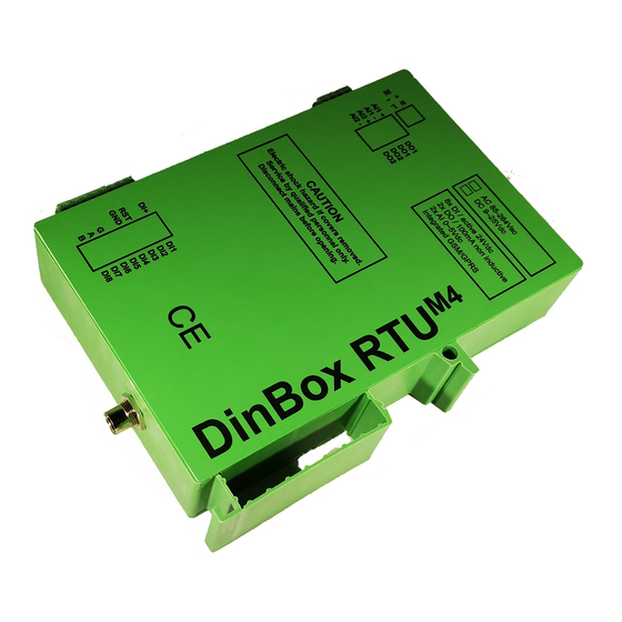
- Page 9 Relative humidity (non condensing) : 85% maximum • IP class : IP20 Housing DinBox RTU M4 is enclosed into a Phoenix UEG-EU-BE housing. This housing has a DIN rail snap slot for easy DIN rail mounting. dimensions 172 mm x 35 mm x 135 mm...
- Page 10 AI1 - 8x DI / active 24Vdc AI2 + 2x DO / 100mA non inductive AI2 - 2x AI 0~5Vdc Integrated GSM/GPRS CAUTION Electric shock hazard if covers removed. Service by qualified personal only. DinBox RTU M4 Disconnect mains before opening.
- Page 11 3.5.1 Power/Mains DinBox RTU M4 must be powered from mains or a DC power source (optional). Optional power backup, during/after a Mains disconnection, is provided via SuperCaps. Power/Mains connection Connect the ac mains or DC power supply to the power connector.
- Page 12 Transmit data From PC to RTU Request to sent From RTU to PC Clear to sent Signal ground AI1 + AI1 - AI2 + AI2 - 1 nc 2 RXD 3 TXD DinBox RTU M4 5 GND 7 RTS 8 CTS...
- Page 13 3.5.4 Analog input connection DinBox RTU M4 can monitor up to 2 non-isolated analog signals. • 12 bit single ended ADC’s (STM32) • input impedance > 100 Kohm • measurement precision > 1 % • input voltage : 0 ~ 5 Vdc 300K 0.1%...
- Page 14 3.5.6 Digital output connection DinBox RTU M4 can control up to 2 digital outputs. • OptoMos Solid State Relais (SSR) • Ron : 35 Ohm maximum • Iload : 120 mA maximum (non inductive load, not protected with a fuse) •...
- Page 15 3.5.8 SIM & MMC/SD card readers DinBox RTU M4 has an internally standard SIM card holder and optionally MMC/SD card reader at the front of the housing. Always disconnect power before inserting or removing a card. LED indicators There are 4 status LED's onto the front of the...
- Page 16 Information Object Address The IEC index (address) of the data item. See the DinBox RTU M4 CI Guide document for more information about the used ASDU and ASDU types. The IOA of the different ASDU's can be freely changed, see next...
- Page 17 Configuration via HTML GUI Configuration of the DinBox RTU M4 can be done through a GUI via HTML. The default ip address of the modem is 192.168.1.44. Username : admin Password : password Click on “login” to enter the configuration pages of the modem.
- Page 18 Status Displays the most important configuration. General...
- Page 19 System info General RTU info • Software version • Uptime time passed after power-on or reset of the RTU Info about the local Ethernet interface: • IPv4 address • Netmask • MAC Address WAN Info about the WAN interface, which is the connection over the mobile network •...
- Page 20 Configuration To change the configuration: change the parameter, press Save Changes on the same page and Reboot the module. Configuration of the local Ethernet interface. IPv4 • IP Address set the IP address of the local Ethernet interface • Subnet Mask set the IP subnet mast of the local Ethernet interface •...
- Page 21 Configuration of the WAN port. General • SIM PIN Pin code for the installed SIM card. If the SIM pin is disabled, the entered SIM pin will not be sent. • Additional AT AT commands that will be executed at startup. Only certain AT-commands are allowed, others are discarded.
- Page 22 Watchdog functions • Connection Teardown Timeout If, for whatever reason, the IEC60870-5-104 master connection is lost during more then x minutes the WAN module will restart it's GPRS/IP stack/TCP server to be sure that the RTU isn't disconnected and not listening to port 2404.
- Page 23 Routing Configuration of the basic router working mode. This mode will make a transparent IP connection from the Ethernet port to the connected mobile network. Outgoing traffic (LAN→WAN) via standard IP Masquerading Incoming traffic (WAN → LAN) • Filter Only allow connections from the given subnet (ip address and netmask, use netmask 255.255.255.255 to only allow one specific IP address).
- Page 24 IEC104 - General Configuration of the general IEC60870-5-104 parameters. General Server Port Port 2404 is standard used for IEC60870-5-104 • communication. Group 1 and 2 configuration It’s possible to create 2 groups of IEC60870-5-104 masters, each with it’s own basic parameters. •...
- Page 25 The IEC 60870-5-104 handshake option is firmware specific and fixed and can be used in cases where the master needs to receive 1 or more predefined ADSU's to recognize a IEC60870-5-104 slave. Contact Bausch Datacom NV if this option is needed.
- Page 26 • Short Pulse (ms) Defines the duration of a short pulse. • Long Pulse (ms) Defines the duration of a long pulse. TI45 46 & 58 59 commands can also have 1 <Short Duration Pulse> or 2<Long Duration Pulse> as Qualifier (QU) bit. Short and Long period can be given here in [ms].
- Page 27 IEC104 - IOA Configuration of the used IEC60870-5-104 addresses (IOA). Monitor IOA addresses for all RTU-hardware related inputs. Control IOA addresses for all RTU-hardware related outputs.
- Page 28 MODBUS - General Configuration of the standard Modbus parameters. RS485 The 2-wire RS485 interface is used to communicate with a (the) Modbus slave(s). • Baudrate Defines the baud rate of the RS485 communication interface. • Data bits Defines the amount of databits [7 - 8]. •...
- Page 29 Modbus communication control • Request Retries Defines the amount of failures after which a IEC60870-5-104 event, with invalid flag set, will be sent to the master. • Request Delay (ms) Defines the delay between between the retries. • IOA Modbus failed The RTU keeps track of whether a Modbus error occurred;...
-
Page 30: Modbus - Mapping
MODBUS - Mapping Configuration of the Modbus mapping parameters. Configuration file There are two ways to enter the Modbus mapping json file : 1. locally via the Configuration – Modbus – Mapping file 2. remotely via FTP transfer Use ‘Browse’ and ‘Upload’ to locally upload a json mapping file. Loaded mapping If a Modbus mapping is present, details can viewed in this table. - Page 31 RTU I/O Configuration of the local digital input’s. DinBox RTU M4 has 8 digital inputs. All inputs are active; the input line must be short-circuited with the common input to activate an input. Rising or positive slope: when the input line is connected to the common input.
- Page 32 The RTU has two ways to detect digital signals onto the 8 digital inputs (DI's): • Standard detection of digital signals When this option is selected the positive and negative slopes of the digital input will be detected with a predefined debounce time (x * 25ms) to exclude spikes. Each slope will be transmitted as an event via an ASDU TI30 to the IEC60870-5-104 master.
- Page 33 RTU Sampling Configuration of sampling of input values by the RTU. DinBox RTU M4 can perform automatically some sampling tasks to sent events to a IEC60870-5-104 master. The following sampling tasks are supported: Supply Voltage When this threshold detection sampling is enabled, the internal power supply...
- Page 34 Analog Inputs When this threshold detection sampling is enabled, a deadband measurement for both analog inputs will be active; the voltage on the analog inputs will be checked after the configured number of seconds. If the voltage has changed by more than, or equal, the entered digital value (0-2048) an event with ASDU TI36 with IOA 420 (AI1 default) &...
-
Page 35: Modbus - Security
MODBUS - Security Configuration of the TLS security. CA Certificate Allows to upload the root certificate (cacert.der) file. Public Certificate Allows to upload the public certificate (cacert_… .der) file. Private Key Allows to upload the private certificate (cakey_… .der) file. Configuration Allows to turn encryption on or off. - Page 36 Each severity level includes the traces for a higher level (traces for info also include traces for warning and error, traces for warning include traces for error). Use the standard Bausch Datacom ‘white’ RJ45 to DB9 serial cable to connect to the serial interface DinBox RTU M4.
-
Page 37: Set Date/Time
Set date/time The time on the DinBox RTU M4 is maintained by an on-board RTC clock and automatically synchronized through the IEC 60870-5-104 protocol. If it is required to set the time manually this can be done via this page. - Page 38 Configuration via the serial interface Use the standard Bausch Datacom ‘white’ RJ45 to DB9 serial cable to connect to the serial interface DinBox RTU M4. The asynchronous parameters are 115.200 bps 8N1 with RTS/CTS flow control enabled. This interface is used to debug the DinBox RTU During startup some basic information is sent.
- Page 39 Remote configuration It’s possible to access the DinBox RTU M4 remotely via Telnet or HTML. This option has to be enabled via the Configuration-Routing page. Leaving either TELNET or HTML checked allows remotely access the TELNET server...
- Page 40 Modbus mapping configuration DinBox RTU M4 has a build-in Modbus <> IEC60870-5-104 mapping. The Modbus device has to be connected onto the 2-wire RS485 interface. The asynchronous parameter are configurable via the Configuration-Modbus-General page. Modbus communication between a master and a slave is working with serial requests and responses over the RS485 interface.
- Page 41 Identifier The identifier used to identify the mapping item. This will be the same as for the “60870-5-104 Configuration tab. Slave address The slave address to sent the Modbus request to. word address The Modbus address [hex] is the slave address space from where to retrieve the Modbus object.
- Page 42 The items for the IEC 60870-5-104 slave can be configured in the “60870-5-104 Configuration” tab. Identifier The identifier used to identify the mapping item. This must be the same as for the corresponding Modbus item. The “IEC 60870-5-104” information object address [dec] used to address the item from the master.
- Page 43 Process information in monitor direction – for inputs: • TI 1 1 bit single point information • TI 7 32 bit bit string • TI 9 MME-A 16 bit measured value, normalized value • TI 11 MME-B 16 bit measured value, scaled value •...
- Page 44 This configuration file should have the extension “.json”. A special program is designed to generate the configuration file for the DinBox RTU M4 from the spreadsheet. This requires either Microsoft excel or OpenOffice to be installed. Upon starting the program “ModbusMappingCreator” a window is displayed to the user: Input file The name of the spreadsheet that has the items configured in OpenOffice (.ods)
- Page 45 5.4.3 Installing the configuration file Installing the configuration in the DinBox RTU M4 can be done remotely via FTP or locally via the HTML GUI. A. Remotely To make this option possible all FTP parameters must be proper configured via the Configuration-Modbus-General page The download must be triggered through the IEC 60870-5-104 command “IOA to trigger...
- Page 46 SSL/TLS Encryption configuration This chapter describes how to set up the DinBox RTU M4 cryptography service in order to allow encrypted communication to occur between DinBox RTU M4 and the IEC 60870-5-104 SCADA system. The encryption is performed using transaction layer security (TLS).
- Page 47 5.5.3 TLS proxy on the SCADA side Bausch Datacom does not provide a Windows or Linux proxy to add TLS encryption functionality to non-TLS applications. Our engineering is using Stunnel to test the DinBox RTU M4 TLS Encryption functionality. Stunnel is a proxy designed to add TLS encryption functionality to existing clients and servers without any changes in the programs' code.
- Page 48 stunnel.conf file example for 3 RTUs [globals] output = C:\Program Files (x86)\DBRTUM4\log\log_stunnel.log cafile = C:\temp\output\cacert.pem verify = 2 [RTU1] client = yes accept = 1001 connect = 10.35.0.11:2404 cert = C:\temp\output\cacert_WS001.pem key = C:\temp\output\cakey_WS001.pem debug = 7 [RTU2] client = yes accept = 1002 connect = 10.35.0.12:2404 cert = C:\temp\output\cacert_WS002.pem...
- Page 49 Emission measurements following EN 55022: Conducted Emission (150 kHz – 30 MHz) Radiated Emission (150 kHz – 3 GHz) Immunity test following EN 55024: EN 61000-4-2: Immunity to Electrostatic Discharges (enclosure) EN 61000-4-3: Immunity to Radiated Electromagnetic fields (enclosure) EN 61000-4-4: Immunity to electrical Fast Transients (230 VAC & I/O’s) EN 61000-4-5: Immunity to surges (230 VAC &...
- Page 50 Appendix A. IEC60870-5-104 information overview The address map for the DinBox RTU M4 is as follows: Object Object type description Type Interrogation Command Clock sync command Battery input Measured Value, Short Floating Point number with time tag (MME C) CSQ input...
Need help?
Do you have a question about the DinBox RTU M4 and is the answer not in the manual?
Questions and answers