Advertisement
Altronix AL600ULB power supply/charger converts a 28VAC/200VA input to a 12VDC or a 24VDC output (see specifications).
Agency Listings:
• UL Recognized component for
UL 294* Access Control System Units.
UL 1481 Standard for Safety for Fire Protective
Signaling Systems.
Input:
• Input 28VAC / 200VA.
Output:
• 12VDC or 24VDC selectable output.
• 6A continuous supply current @ 12VDC or 24VDC.
• Filtered and electronically regulated output.
Battery Backup:
• Built-in charger for sealed lead acid or gel type batteries.
• Maximum charge current 0.7A.
*Access Control Performance Levels: Destructive Attack - N/A; Endurance - IV; Line Security - I; Stand-by Power - IV.
Power Supply Output Selection:
Output VDC
Switch Position
12VDC
SW1 ON
24VDC
SW1 OFF
Stand-by Specifications:
Output
12VDC / 40 AH Battery
24VDC / 12 AH Battery
24VDC / 40 AH Battery
The AL600ULB should be installed in accordance with article 760 of The National Electrical Code as well as NFPA 72 and all
applicable Local Codes.
1. Mount the AL600ULB in the desired location/enclosure (mounting hardware included).
2. Set the AL600ULB to the desired DC output voltage by setting SW1 to the appropriate position
(refer to Power Supply Output Selection chart).
3. Connect two (2) 28VAC/100VA transformers (connected in parallel) to the terminals marked [AC].
Use 14 AWG or larger for all power connections (Battery, DC output, AC input).
Use 22 AWG to 18 AWG for power-limited circuits (AC Fail/Low Battery reporting).
Keep power-limited wiring separate from non power-limited wiring (115VAC / 60Hz Input, Battery Wires).
Minimum 0.25" spacing must be provided.
CAUTION: Do not touch exposed metal parts. Shut branch circuit power before installing or servicing equipment.
There are no user serviceable parts inside. Refer installation and servicing to qualified service personnel.
4. Measure output voltage before connecting device. This helps avoiding potential damage.
5. Connect devices to be powered to the terminals marked [+ DC –] (Fig. 1, pg. 2).
When servicing the unit, AC mains should be removed.
6. For Access Control applications batteries are optional. When batteries are not used, a loss of AC will result in the loss of output
voltage. When the use of stand-by batteries is desired, they must be lead acid or gel type.
Connect battery to the terminals marked [+ BAT –] (Fig. 1, pg. 2).
7. Connect appropriate signaling notification devices to [AC FAIL & BAT FAIL] (Fig. 1, pg. 2) supervisory relay outputs.
Note: When used in fire alarm, burglar alarm or access control applications, "AC Fail" relay must be used to provide a visual
indication of AC power on.
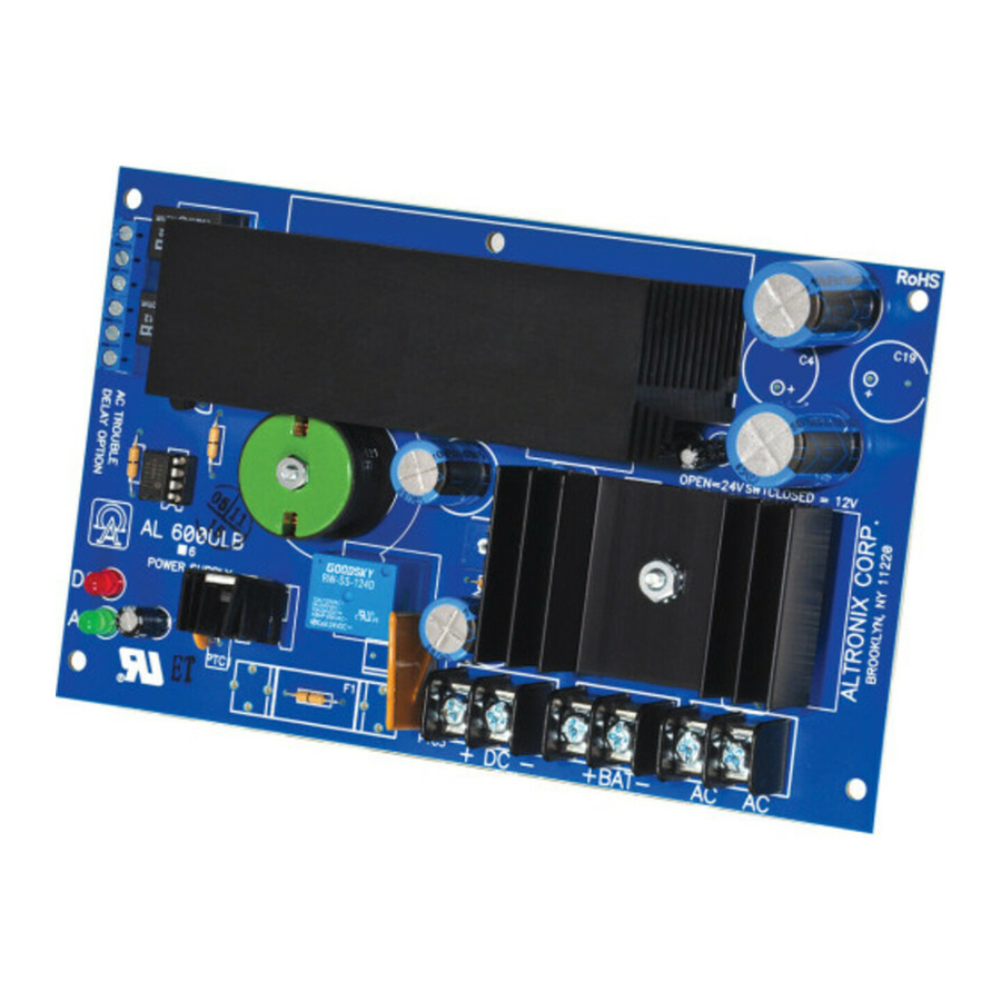
AL600ULB
UL Recognized Power Supply/Charger
Overview:
Specifications:
4 hr. of Stand-by and
5 Minutes of Alarm
Stand-by = 6A
Alarm = 6A
–
Stand-by = 6A
Alarm = 6A
Installation Instructions:
Battery Backup (cont'd):
• Automatic switch over to stand-by battery when AC fails.
• Zero voltage drop when switched over to battery backup.
Visual Indicators:
• AC input and DC output LED indicators.
Supervision:
• AC fail supervision (form "C" contacts).
• Low battery and battery presence supervision
(form "C" contacts).
Additional Features:
• Short circuit and thermal overload protection.
Board Dimensions (W x L x H approximate):
4.3" x 7.1" x 2.3" (109.2mm x 180.3mm x 58.4mm).
24 hr. of Stand-by and
5 Minutes of Alarm
Stand-by = 1.0A
Alarm = 6A
Stand-by = 200mA
Alarm = 6.0A
Stand-by = 1.0A
Alarm = 6A
60 hr. of Stand-by and
5 Minutes of Alarm
Stand-by = 300mA
Alarm = 6A
–
Stand-by = 300mA
Alarm = 6A
Advertisement
Table of Contents

Related Manuals for Altronix AL600ULB


Summary of Contents for Altronix AL600ULB
- Page 1 Alarm = 6A Installation Instructions: The AL600ULB should be installed in accordance with article 760 of The National Electrical Code as well as NFPA 72 and all applicable Local Codes. 1. Mount the AL600ULB in the desired location/enclosure (mounting hardware included).
- Page 2 Terminal Legend Function/Description AC/AC Connect 28VAC to these terminals from two transformers (Altronix T2428100) connected in parallel. + DC – 12VDC or 24VDC @ 6A continuous non power-limited output. Used to notify loss of AC power, e.g. connect to annunciator/alarm panel. Relay normally energized when AC power is present.
Need help?
Do you have a question about the AL600ULB and is the answer not in the manual?
Questions and answers