
Related Manuals for Wenglor UMF402U035


Summary of Contents for Wenglor UMF402U035
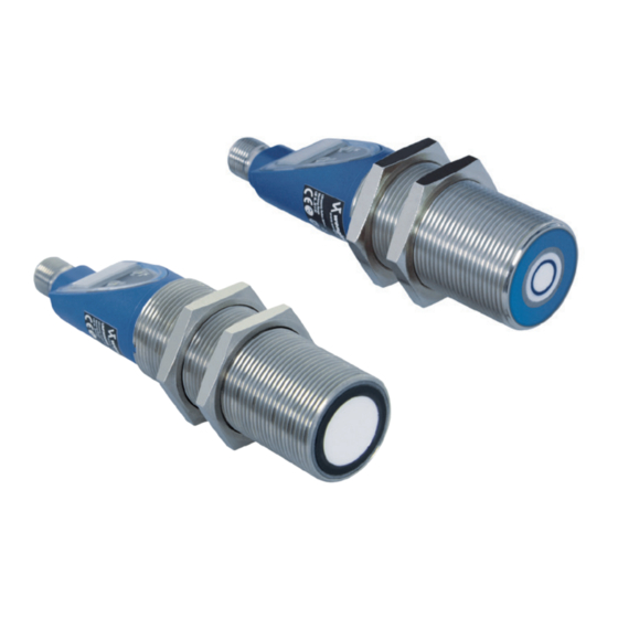
- Page 1 UMF402U035 UMF303U035 Reflex Sensor with Analog Output Operating Instructions Right of modifications reserved Available as PDF version only Version 1.1.0 Status: 08.04.2019 www.wenglor.com...
-
Page 2: Table Of Contents
Table of Contents Proper Use ...............................3 Safety Precautions ..........................3 EU Declaration of Conformity ........................3 Technical Data ............................4 4.1 Sonic cone Diagram..........................6 4.1.1 Measurement a diameter of 27 mm 4.1.2 Measurement on a 100 × 100 mm plate 4.2 Connection Diagram ..........................8 4.3 Housing dimensions .......................... -
Page 3: Proper Use
• Not a safety component in accordance with the EU Machinery Directive. 3. EU Declaration of Conformity The EU d eclaration of conformity can be found on our website at www.wenglor.com in download area. RoHS Reflex Sensor with Analog Output... -
Page 4: Technical Data
4. Technical Data UMF402U035 UMF303U035 Ultrasonic Working Range 50...400 mm 200...3000 mm Measuring Range 350 mm 2800 mm Reproducibility, maximum 1 mm 4 mm Linearity Deviation 3 mm 4 mm Resolution 0,1 mm 0,3 mm Ultrasonic Frequency 300 kHz 120 kHz Opening Angle <12°... - Page 5 Reproducibility in mm Set filter UMF402U035 UMF303U035 Filter 0 (default) Filter 1 Filter 2 Filter 3 Filter 4 Filter 5 Filter 6 Filter 7 UMF303U035 Filter value Switching frequency (Hz) Response time (ms) UMF402U035 Filter value Switching frequency (Hz) Response time (ms)
-
Page 6: Sonic Cone Diagram
4.1 Sonic cone Diagram 4.1.1 Measurement a diameter of 27 mm UMF402U035 Ob/mm UMF303U035 1000 1200 1400 1600 1800 2000 -100 -150 -200 Ob/mm Standard sonic cone Standard Schallkeule Standard sonic cone Standard Schallkeule Standard sonic cone Mittelbreite Schallkeule Standard Schallkeule... -
Page 7: Measurement On A 100 × 100 Mm Plate
4.1.2 Measurement on a 100 × 100 mm plate UMF402U035 Ob/mm UMF303U035 1000 1500 2000 2500 3000 3500 -100 -150 -200 -250 Ob/mm Standard sonic cone Standard Schallkeule Standard sonic cone Standard Schallkeule Standard sonic cone Mittelbreite Schallkeule Medium-width sonic cone... -
Page 8: Connection Diagram
4.2 Connection Diagram Supply Voltage "+" Switching Output NO/ Switching Output NC/IO-Link/ Contamination Output/Error Output (NC) T/SY Teach Input/Synchronisation Analog Output – Supply Voltage "0 V" 4.3 Housing dimensions UMF402U035 UMF303U035 = Sensing Face Technical Data... -
Page 9: Control Panel
4.4 Control Panel 80 = Mode Button/Switching Status Indicator 81 = Plus Button/Error Indication 60 = Display 4.5 Complementary Products (see catalog) wenglor offers Connection Technology for field wiring. Suiting Mounting Technology No. Suiting Connection Technology No. Baffle Plate IO-Link Master... -
Page 10: Mounting Instructions
5. Mounting instructions During mounting and operation of the sensors, the corresponding electrical and mechanical regulations, as well as safety regulations must be observed. The sensor must be protected from mechanical impact. The product has to be mounted so that the mounting position can not be changed. •... -
Page 11: Causes For Triggering Error Indication (Led Plus Button)
5.1 Causes for Triggering Error Indication (LED Plus Button) • Too little ultrasonic is reflected. • Very small objects, or objects which do not reflect sound well (sound-absorbing objects), are located within the working range. • Incorrect installation • Object outside of the working range •... -
Page 12: Overview Of Functions
Filter Settings Select Operating Mode Participant Adress Multiplex Fix Number of Multiplex Participants Select Ultrasonic Cudgel Reset 6.2 Delivery status Technical Data UMF402U035 UMF303U035 Teach-In Input Enabled Switching Logic (SL) Normally open (NO) Teach Mode (PL) Foreground Teach-In Output Function (OUP) -
Page 13: Menu Structure
6.3 Menu Structure The Structure of the Configuration Menu of the Sensor: + Button Display Mode (run) Leave configuration menu + Button Teach-In Switching Point (SP U) Teach M Button ¹ Only visible if Teach-In Mode „Window“ is set. + Button Teach-In Point 1 (SP 1) Teach ²... -
Page 14: Settings
7. Settings 7.1 run (display mode) By pressing the plus key, you leave the configuration menu. 7.2 SP U (Teach-In Switching Point) Align Sensor to the object (SP U). Press Plus key. The dispay doesn't change from Distance Value and SP U. ... -
Page 15: Change Teach-In Mode)
7.5 PL (Change Teach-In Mode) Setting Description Foreground Teach-In The Switching Distance to an object is teached. If the object is located within the teached distance, or closer to the Sensor, the Sensor is switched. Window Teach-In The sensor works by means of two switching points. -
Page 16: Ana (Set Analog Voltage Output Or Current Output)
7.8 AnA (Set Analog Voltage Output or Current Output) Configuration Description Voltage Output At the Analog Output the distance between Sensor and object is given out as Voltage Value between 0 V and 10 V. Current Output At the Analog Output the distance between Sensor and object is given out as Current Value between 4 mA and 20 mA. -
Page 17: Cl (Select Characteristic Curve)
7.10 CL (Select Characteristic Curve) The Analog Output can be operated with rising or falling Characteristic Curve. Setting Description Characteristic Curve rising Analog Output 20 mA/10 V Distance to Object 4 mA/0 V Characteristic Curve falling Analog Output 20 mA/10 V Distance to Object 4 mA/0 V 7.11 FL (Set Filter) -
Page 18: Fun (Select Operating Mode)
7.12 Fun (Select Operating Mode) Synchronous Mode Multiplex Mode Master Slave Slave Master Slave Slave Several sensors send ultrasonic impulses Several sensors send ultrasonic impulses simultaneously (synchron). alternately (cyclic). In both operating modes the Sensors are connected to each other through pin 5 (T/SY). Please note: Synchronous and multiplex operation are only possible with sensors of the same type. -
Page 19: Ad*¹ (Set Multiplex Participants Address)
Multiplex Slave The Sensor is in multiplex slave mode. Via pin 5, the master transmits tempo- rarily delayed signals to the slaves so that they transmit consecutively clocked ultrasonic impulses. Multiplex Master The Sensor is in multiplex master mode. It sends out impulses automatically to the connected Slaves via Pin 5 (T/SY), in order that they all send out Ultrasonic impulses one after another. -
Page 20: Sen (Select Ultrasonic Cudgel)
7.15 SEn (Select Ultrasonic Cudgel) Setting Description Extra small sonic cone* Small sonic cone* Medium-width sonic cone* Standard sonic cone* * View 4.1 Sonic cone Diagram rES (Reset) The selected sensor settings are reset to the delivery condition. To this end, the plus key has to be pushed for approx. -
Page 21: External Teach-In
8. External Teach-In Before a external Teach-In process the desired Teach-In Mode has to be set at the Sensor one time in advance (view Chapter 7.5). 8.1 External Foreground Teach-In Align the Sensor to the object. Connect the Teach input to 18…30 V DC for approx. 5 sec. until PLU flashes. In the next step, disconnect the voltage supply from the Teach input until SPU flashes. -
Page 22: Io-Link
• Do not clean with solvents or cleansers which could damage the device. 12. Proper Disposal wenglor sensoric GmbH does not accept the return of unusable or irreparable products. Respectively valid national waste disposal regulations apply to product disposal. 13. Appendix 13.1 Change Index, Operating Instructions... - Page 23 Reflex Sensor with Analog Output...
Need help?
Do you have a question about the UMF402U035 and is the answer not in the manual?
Questions and answers