Table of Contents
Advertisement
Quick Links
Advertisement
Chapters
Table of Contents

Related Manuals for Rohde & Schwarz R&S NGL200 Series


Summary of Contents for Rohde & Schwarz R&S NGL200 Series
- Page 1 ® R&S NGL200/NGM200 Power Supply Series User Manual (;ÜåT2) 1178873602 Version 09...
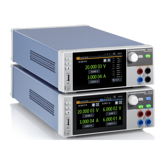
- Page 2 ® This manual describes the following R&S NGL/NGM models with firmware version 1.00 or higher: ● ® R&S NGL201 Single-channel power supply 60W (3638.3376.02) ● ® R&S NGL202 Two-channel power supply 120W (3638.3376.03) ● ® R&S NGM201 Single-channel power supply 60W (3638.4472.02) ●...
- Page 3 Safety Instructions Instrucciones de seguridad Sicherheitshinweise Consignes de sécurité Risk of injury and instrument damage The instrument must be used in an appropriate manner to prevent electric shock, fire, personal injury or instrument damage. Do not open the instrument casing. ●...
- Page 4 Gefahr von Verletzungen und Schäden am Gerät Betreiben Sie das Gerät immer ordnungsgemäß, um elektrischen Schlag, Brand, Verletzungen von Personen oder Geräteschäden zu verhindern. Öffnen Sie das Gerätegehäuse nicht. ● Lesen und beachten Sie die "Grundlegenden Sicherheitshinweise", ● die als gedruckte Broschüre dem Gerät beiliegen. Lesen und beachten Sie die Sicherheitshinweise in den folgenden ●...
-
Page 5: Table Of Contents
® Contents R&S NGL200/NGM200 Contents 1 Documentation Overview..............9 Manuals..........................9 Data Sheet........................10 Release Notes, Open Source Acknowledgment............10 Application Notes, Application Cards, Videos............10 2 Welcome to R&S NGL/NGM..............11 3 Important Notes..................12 Symbols........................12 Ambient Conditions....................12 Measurement Categories................... 13 Mains Voltage...................... - Page 6 ® Contents R&S NGL200/NGM200 4.4.2 Contacting Customer Support..................28 5 Operating Basics..................29 Display Overview......................29 5.1.1 Status Bar Information....................29 5.1.2 Channel Display Area....................32 Using the Touchscreen....................33 5.2.1 Using Gestures......................33 5.2.2 Accessing Functionality in the Home Window.............. 33 5.2.2.1 Settings Button......................34 5.2.2.2 Voltage and Current Inputs...................
- Page 7 ® Contents R&S NGL200/NGM200 Protection........................58 6.5.1 Overcurrent Protection (OCP)..................58 6.5.2 Overvoltage Protection (OVP)..................59 6.5.3 Overpower Protection (OPP)..................60 6.5.4 Safety Limits........................61 Trigger / Digital I/O...................... 62 Advanced Features..................... 67 6.7.1 Arbitrary.........................67 6.7.2 Ramp..........................70 User Key........................71 Screenshot........................72 6.10 Data Logging....................... 73 6.11 FastLog........................
- Page 8 ® Contents R&S NGL200/NGM200 System Settings Commands..................99 Display Commands....................101 Trigger Commands....................102 Configuration Commands..................105 7.5.1 Channel Selection....................... 106 7.5.2 Safety Limit Setting..................... 107 7.5.3 Voltage Setting......................111 7.5.4 Current Setting......................114 7.5.5 Resistance Setting.......................117 7.5.6 Combined Setting of Voltage and Current Setting............119 7.5.7 Output Setting......................
- Page 9 ® Contents R&S NGL200/NGM200 Status Reporting System..................186 A.3.1 Structure of a SCPI Status Register................186 List of Commands................192 Index....................197 User Manual 1178.8736.02 ─ 09...
- Page 10 ® Contents R&S NGL200/NGM200 User Manual 1178.8736.02 ─ 09...
-
Page 11: Documentation Overview
® Documentation Overview R&S NGL200/NGM200 Manuals 1 Documentation Overview This section provides an overview of the R&S NGL/NGM user documentation. 1.1 Manuals You find the documents on the R&S NGL/NGM product page at: www.rohde-schwarz.com/product/ngl200 www.rohde-schwarz.com/product/ngm200 Getting Started Introduces the R&S NGL/NGM power supply series and describes how to set up and start working with the instrument. -
Page 12: Data Sheet
® Documentation Overview R&S NGL200/NGM200 Application Notes, Application Cards, Videos 1.2 Data Sheet The datasheet contains the technical specifications of the R&S NGL/NGM power sup- ply series. It also lists all options with their order numbers and accessories. www.rohde-schwarz.com/brochure-datasheet/ngl200 www.rohde-schwarz.com/brochure-datasheet/ngm200 1.3 Release Notes, Open Source Acknowledgment The release notes list new features, improvements and known issues of the current firmware version, and describe the firmware installation. -
Page 13: Welcome To R&S Ngl/Ngm
® Welcome to R&S NGL/NGM R&S NGL200/NGM200 2 Welcome to R&S NGL/NGM The one or two-channel power supply series are based on a classical transformer con- cept with linear regulators. This concept allows the instrument to achieve highest accu- racy and lowest residual ripple. The R&S NGL/NGM power supply series feature galvanically isolated, floating over- load and short-circuit proof outputs. -
Page 14: Important Notes
® Important Notes R&S NGL200/NGM200 Ambient Conditions 3 Important Notes 3.1 Symbols Caution, general danger zone Ground PE terminal ON (supply voltage) OFF (supply voltage) Ground terminal 3.2 Ambient Conditions The allowed operating temperature ranges from +5 °C to +40 °C (pollution category 2). The maximum relative humidity (without condensation) is at 80 %. -
Page 15: Measurement Categories
® Important Notes R&S NGL200/NGM200 Mains Voltage allowed limit, overtemperature protection is triggered and the affected outputs are switched off automatically. Air circulation Do not obstruct the ventilation holes! 3.3 Measurement Categories This instrument is designed for supplying power-on circuits that are only indirectly con- nected to the low voltage mains or not connected at all. -
Page 16: Limits
® Important Notes R&S NGL200/NGM200 Limits against the spring pressure until it locks into place. The use of mended fuses or short circuiting the fuse holder is prohibited. Resulting damages are not covered by the war- ranty. Safe operation If the instrument is not in use, it must be switched off at the mains switch for safety rea- sons. -
Page 17: Getting Started
® Getting Started R&S NGL200/NGM200 Putting into Operation 4 Getting Started 4.1 Putting into Operation This chapter describes how to set up the R&S NGL/NGM power supply series for the first time. Risk of injury due to disregarding safety information Observe the information on appropriate operating conditions provided in the data sheet to prevent personal injury or damage to the instrument. -
Page 18: Safety
® Getting Started R&S NGL200/NGM200 Putting into Operation Risk of instrument damage during operation An unsuitable operating site or test setup can cause damage to the instrument and the connected devices. Ensure the following operating conditions before you switch on the instrument: ●... -
Page 19: Intended Operation
® Getting Started R&S NGL200/NGM200 Putting into Operation connected to a protective earth conductor. The instrument is designed in compliance with the regulations of protection class I. For safety reasons, the instrument may only be operated with authorized safety sock- ets. - Page 20 ® Getting Started R&S NGL200/NGM200 Putting into Operation Use only the power cable included in the delivery package. See "Delivery package" on page 19. Before each measurement, measuring cables must be inspected for damage and replaced if necessary. Damaged or worn components can damage the instrument or cause injury.
-
Page 21: Unpacking And Checking The Instrument
® Getting Started R&S NGL200/NGM200 Putting into Operation 4.1.3 Unpacking and Checking the Instrument Unpack the R&S NGL/NGM power supply carefully and check the content of the pack- age. ● Check the equipment for completeness using the delivery note and package con- tents list for the various items. -
Page 22: Rack Mounting
® Getting Started R&S NGL200/NGM200 Instrument Tour Figure 4-1: Operating positions Positioning of instrument The instrument must be positioned in a manner that allows you to disconnect the unit from the mains at any time and without restrictions. 4.1.4.2 Rack Mounting The instrument can be installed in a 19"... - Page 23 ® Getting Started R&S NGL200/NGM200 Instrument Tour The R&S NGL/NGM has one output channel for NGL201, NGM201 models and two output channels for NGL202, NGM202 models. Figure 4-2: Front panel of R&S NGL/NGM with 2 channels 1 = Display with touch screen 2 = Menu control keys 3 = Rotary knob and back key 4 = Output and channel keys...
-
Page 24: Rear Panel
® Getting Started R&S NGL200/NGM200 Instrument Tour Output and channel keys (4) The channel key allows you to select the power supply channel to source or sink power. The output key allows you to enable or disable the output power on the channel key. - Page 25 ® Getting Started R&S NGL200/NGM200 Instrument Tour 13 = Ethernet (LAN) connector 14 = Optional IEEE-488 (GPIB) interface 15 = Digital I/O connector AC inlet with fuse holder and voltage selector (8) Main supply cord Do not use detachable mains supply cord with inadequate rating. The power cable must be plugged in before signal circuits can be connected.
-
Page 26: Switching On The Instrument
® Getting Started R&S NGL200/NGM200 Instrument Tour Digital I/O connector (15) The Digital I/O option (R&S NGL-K103 or R&S NGM-K103) must be installed for this function to be available in the instrument. The specified voltages are 0 V to 24 V for all output pins and 0 V to 15 V for all input pins. -
Page 27: Trying Out The Instrument
® Getting Started R&S NGL200/NGM200 Trying Out the Instrument To change power fuse / mains voltage setting: 1. Peel off the yellow label sticker on the AC inlet. 2. Release the latch of the fuse holder which is located at both side of the socket and pull it out. -
Page 28: Setting The Output Voltage And Current
® Getting Started R&S NGL200/NGM200 Trying Out the Instrument Source and sink current The R&S NGL/NGM power supply series are 2 quadrant power supplies which may both source and sink current. When the voltage across the output terminal exceeds the set voltage, current flows into the instrument. -
Page 29: Maintenance And Support
® Getting Started R&S NGL200/NGM200 Maintenance and Support Color illuminated on front panel keys and display Operating mode font color of voltage and current in home window Constant voltage mode (CV) Green Constant current mode (CC) Constant resistance mode (CR) Note: Instrument is operated in sink mode and Cyan "Constant Resistance"... -
Page 30: Contacting Customer Support
® Getting Started R&S NGL200/NGM200 Maintenance and Support 4.4.2 Contacting Customer Support Technical support – where and when you need it For quick, expert help with any Rohde & Schwarz product, contact our customer sup- port center. A team of highly qualified engineers provides support and works with you to find a solution to your query on any aspect of the operation, programming or applica- tions of Rohde &... -
Page 31: Operating Basics
® Operating Basics R&S NGL200/NGM200 Display Overview 5 Operating Basics 5.1 Display Overview The following displays the home window of R&S NGL/NGM. It shows the output volt- age and current level, status bar information and control settings of the instrument. Figure 5-1: Home window of R&S NGL/NGM with 2 channels 1 = Device status bar 2 = Channel status bar... - Page 32 ® Operating Basics R&S NGL200/NGM200 Display Overview Device status bar Function Description If touch input is disabled, the icon is displayed and Touchscreen highlighted in yellow. Chapter 5.3.1.3, "User Key", on page 40. If a SCPI command is received successfully, the SCPI command icon blinks once in white.
- Page 33 ® Operating Basics R&S NGL200/NGM200 Display Overview Channel status bar Function Description Channel number Channel number indication. Operation mode The R&S NGL/NGM has three operating modes: ● CV: Constant voltage mode ● CC: Constant current mode ● CR: Constant resistance mode. The R&S NGL/NGM goes into this mode when operates in sink mode and the "Constant Resistance"...
-
Page 34: Channel Display Area
® Operating Basics R&S NGL200/NGM200 Display Overview Function Description If enabled, the icon is highlighted in white. "Output Delay" The delay is the time between activation of the out- put and applying voltage to the output. Chapter 6.2.3, "Output", on page 48. If sense connection is detected, the icon is highligh- Sense connection ted in white. -
Page 35: Using The Touchscreen
® Operating Basics R&S NGL200/NGM200 Using the Touchscreen Figure 5-3: Color coding of difference operating conditions Color Operating mode Description DVM mode Available only with NGM models. Display DVM measurement. Editing mode A solid blue cursor is shown when an item is selected. CV mode Active outputs are operated in a constant voltage mode. -
Page 36: Settings Button
® Operating Basics R&S NGL200/NGM200 Using the Touchscreen 5.2.2.1 Settings Button The "Settings" button navigates to the device/channel menu window where you can set device or individual channel settings on the instrument. Long-press on the "Settings" button brings you to the graphical view window for mea- surements. -
Page 37: Voltage And Current Inputs
® Operating Basics R&S NGL200/NGM200 Using the Touchscreen 5.2.2.2 Voltage and Current Inputs You can directly change the voltage and current level in the respective channel display area. 1. Select the voltage or current field in the channel display area to set value. The R&S NGL/NGM displays the on-screen keypad to enter value. -
Page 38: Input Data
® Operating Basics R&S NGL200/NGM200 Using the Touchscreen Figure 5-6: Display of channel overview window 1 = Minimum, maximum and average values for power, voltage and current 2 = Calculation of energy result 3 = Count of samples collected 4 = Channel display area of selected channel 5 = Digital I/O trigger of selected channel 5.2.3 Input Data The R&S NGL/NGM provides an on-screen keypad for you to enter numerical values. -
Page 39: Front Panel Keys
® Operating Basics R&S NGL200/NGM200 Front Panel Keys 2. Select "&123" or "ABC" key to switch between alphabet and numeric input data. Figure 5-8: Alphanumeric input data 5.3 Front Panel Keys For an overview of the front panel keys, see Figure 4-2. - Page 40 ® Operating Basics R&S NGL200/NGM200 Front Panel Keys The R&S NGL/NGM displays the home window. 2. Select the "Settings" button on the required channel display area. Alternatively, press [Settings] key. 3. Select the "Device" tab to access the device menu. Figure 5-9: Device menu Menu Description...
- Page 41 ® Operating Basics R&S NGL200/NGM200 Front Panel Keys Menu Description "User Button" Configures the shortcut key action (e.g. screenshot, trigger, toggle logging, reset statistics, toggle touch). "Screenshot" Captures screen image of the instrument. "CSV Settings" Configures the file formatting for CSV file. "Data &...
-
Page 42: User Key
® Operating Basics R&S NGL200/NGM200 Front Panel Keys Menus Description "Output" Configures the output impedance, output delay time, trigger actions and output mode (sink/source) of the output. "Arbitrary" Configures the arbitrary sequence, sequence repeatability response and the sequence ending behavior. "Ramp"... -
Page 43: Output And Channel Controls
® Operating Basics R&S NGL200/NGM200 Power Derating Rotary knob The rotary knob has several functions: ● Increments (clockwise direction) or decrements (counter-clockwise direction) any kind of numeric value when in editing mode ● Navigates up (clockwise direction) or down (counterclock-wise direction) the menu or menu items when rotated ●... -
Page 44: Operation Modes
® Operating Basics R&S NGL200/NGM200 Operation Modes Figure 5-11: Output performance graph 5.5 Operation Modes The R&S NGL/NGM operates in three different modes, i.e. the constant voltage (CV), constant current (CC) and constant resistance (CR). The instrument switches automat- ically between CV and CC depending on the connected load. When CR is configured, the instrument is not switched to CR mode automatically, it will operate in CR mode when sinking but source in CV or CC mode. - Page 45 ® Operating Basics R&S NGL200/NGM200 Operation Modes If I reaches I , the instrument switches to CC mode, i.e. the output current remains constant and limited to I even if the load increases. Instead, the output voltage V decreases to almost zero with a short circuit. In CC mode, the font text in the channel display area changes to red.
-
Page 46: Instrument Functions
® Instrument Functions R&S NGL200/NGM200 Setting the Channels Voltage and Current 6 Instrument Functions 6.1 Setting the Channels Voltage and Current The R&S NGL/NGM comes with the following instrument models: Models Channels NGL201, NGM201 NGL202, NGM202 Ch1, Ch2 Toggle the respective channel key ([Ch1], [Ch2] ) on the front panel to select these channels. -
Page 47: Activating The Channels Output
® Instrument Functions R&S NGL200/NGM200 Activating the Channels Output For more information on the operation modes, see Chapter 5.5, "Operation Modes", on page 42. Figure 6-2: Voltage and current settings in the instrument 6.2 Activating the Channels Output The outputs of all the channels (Ch1, Ch2) can be switched on or off by toggling the [Output] key on the front panel. -
Page 48: Set Constant Resistance
® Instrument Functions R&S NGL200/NGM200 Activating the Channels Output Figure 6-3: Output of Ch2 in CV mode 6.2.1 Set Constant Resistance By enabling the constant resistance (CR) mode, you can operate the R&S NGL/NGM as an electronic load in sink mode. This allows you to perform testing that requires a constant load resistor in your application. -
Page 49: Fast Transient Response
® Instrument Functions R&S NGL200/NGM200 Activating the Channels Output Figure 6-4: Constant resistance dialog 6.2.2 Fast Transient Response With fast transient response, the R&S NGL/NGM is able to quickly stabilize the output voltage upon a step change in the load current. Load transient recovery time can be switched between 30 μs ("Fast Transient Response"... -
Page 50: Output
® Instrument Functions R&S NGL200/NGM200 Activating the Channels Output 3. Activate the "Fast Transient Response" from the menu. The R&S NGL/NGM applies the fast transient response on the operating condition and displays the "Fast Transient Response" icon on the selected channel status bar information. -
Page 51: Delay
® Instrument Functions R&S NGL200/NGM200 Activating the Channels Output The R&S NGL/NGM displays the "Output Impedance" dialog. 2. Set the required value. The R&S NGL/NGM displays the onscreen keypad for entry. 3. Confirm value with the unit keys. The output impedance control loop depends on the setting "Fast Transient Response". Chapter 6.2.2, "Fast Transient Response", on page 47. -
Page 52: Trigger Events
® Instrument Functions R&S NGL200/NGM200 Activating the Channels Output Figure 6-7: Output delay at the output terminals When the instrument output delay is activated, the front panel of the respective chan- nel key (i.e [Ch1], [Ch2]) blinks in green and a "DELAY" red text is displayed at the channel display area of the respective channel. -
Page 53: Output Mode
® Instrument Functions R&S NGL200/NGM200 Activating the Channels Output The R&S NGL/NGM displays the "Trigger" dialog. 3. Select the required trigger action. ● "Output On": If triggered, the selected output channel is turned on. ● "Output Off": If triggered, the selected output channel is turned off. ●... -
Page 54: Ranges / Digital Voltmeter (Dvm)
® Instrument Functions R&S NGL200/NGM200 Ranges / Digital Voltmeter (DVM) 6.3 Ranges / Digital Voltmeter (DVM) Instrument option R&S NGM-K104 (P/N: 3643.9927.02) option is required for Digital Voltmeter measure- ments. Ranges / Digital Voltmeter (DVM) is only available on NGM devices. Sense connection has to be connected to the load for better performance. - Page 55 ® Instrument Functions R&S NGL200/NGM200 Ranges / Digital Voltmeter (DVM) Figure 6-10: Range/DVM dialog Note: The "Voltage Autorange" and "Voltage Range" are not available if DVM is enabled. 4. Activate the "Enable DVM Measurement" menu item. The R&S NGL/NGM enables the DVM measurement and displays a DVM text in the channel display area.
-
Page 56: Battery Simulator
® Instrument Functions R&S NGL200/NGM200 Battery Simulator 10 A Accuracy from 0 A to 10 A. Accuracy from 0 A to 1 A. 100 mA Accuracy from 0 A to 100 mA. 10 mA Accuracy from 0 A to 10 mA. 6.4 Battery Simulator Instrument option R&S NGM-K106 (P/N: 3636.6626.02) option is required. - Page 57 ® Instrument Functions R&S NGL200/NGM200 Battery Simulator Table 6-2: Battery simulator parameters Battery simulator parameters Descriptions The battery symbol represents the state of charge. The light blue bar indicates the open circuit voltage and the dark blue bar indicates the terminal voltage. The differences between both bars show the voltage drops on internal resistance.
- Page 58 ® Instrument Functions R&S NGL200/NGM200 Battery Simulator Figure 6-12: Battery simulator dialog 4. Select the "Load from file..." to load the battery model file. The R&S NGM opens a dialog to select the source and file location. 5. Select the required source and file location. Alternatively, select "New file"...
- Page 59 ® Instrument Functions R&S NGL200/NGM200 Battery Simulator Figure 6-13: Battery model editor dialog 1. Configure the "Battery Model Editor" with the required state of charge (SoC), open- circuit voltage (Voc) and internal resistance (ESR). The R&S NGM displays the on-screen keypad for data entry. The R&S NGL/NGM displays the on-screen keypad for data entry.
-
Page 60: Protection
® Instrument Functions R&S NGL200/NGM200 Protection 6.5 Protection There are various ways in which the R&S NGL/NGM protects itself and the connected load from damage due to overvoltage, overcurrent and overpower drawn by the load during testing. 1. Press [Settings] key. The R&S NGL/NGM displays the device/channel menu window. -
Page 61: Overvoltage Protection (Ovp)
® Instrument Functions R&S NGL200/NGM200 Protection Figure 6-14: Overcurrent protection dialog 2. Activate the "Enabled" menu item. The R&S NGL/NGM enables the OCP and displays the OCP icon on the selected channel status bar information. 3. Set the required "Fuse Delay Time" and "Fuse Delay At Output-On". The R&S NGL/NGM displays the on-screen keypad to set the values. -
Page 62: Overpower Protection (Opp)
® Instrument Functions R&S NGL200/NGM200 Protection Figure 6-15: Overvoltage protection dialog 2. Activate the "Enabled" menu item. The R&S NGL/NGM enables the OVP and displays the OVP icon on the selected channel status bar information. 3. Set the required level for OVP. The R&S NGL/NGM displays the on-screen keypad to set the value. -
Page 63: Safety Limits
® Instrument Functions R&S NGL200/NGM200 Protection 2. Activate the "Enabled" menu item. The R&S NGL/NGM enables the OPP and displays the "Overpower Protection (OPP)" icon on the selected channel status bar information. 3. Set the required level for OPP. The R&S NGL/NGM displays the on-screen keypad to set the value. 4. -
Page 64: Trigger / Digital I/O
® Instrument Functions R&S NGL200/NGM200 Trigger / Digital I/O 6.6 Trigger / Digital I/O Digital I/O pins voltage rating Do not exceed the maximum voltage rating of the Digital I/O pins when supplying vol- tages to the pins. The specified voltages are 0 V to 24 V for all output pins and 0 V to 15 V for all input pins. - Page 65 ® Instrument Functions R&S NGL200/NGM200 Trigger / Digital I/O Figure 6-18: Overview of trigger IO system Table 6-3: Trigger-in signals Trigger-in parameters Source Descriptions Ext. Trigger Ch1 Digital In, pin 2 of Digi- If detected, corresponding trigger-out parameters tal I/O connector are triggered.
- Page 66 ® Instrument Functions R&S NGL200/NGM200 Trigger / Digital I/O Trigger-in parameters Source Descriptions CC, CV, CR, Protection, Sink Operation Mode If respective channel operation modes, protection event or sink mode is detected, corresponding trigger-out parameters are triggered. Figure 6-18. User button User button If detected, corresponding trigger-out parameters are triggered.
- Page 67 ® Instrument Functions R&S NGL200/NGM200 Trigger / Digital I/O Figure 6-19: Digital output fault signal Digital I/O connector The Digital I/O connector is located below the GPIB connector, see Chapter 4.2.1.2, "Rear Panel", on page 22. Figure 4-4 Table 4-2 for the Digital I/O connector and pins layout.
- Page 68 ® Instrument Functions R&S NGL200/NGM200 Trigger / Digital I/O 4. Select "Enable" and set it "On" to enable the trigger-in setting. 5. Select "Back" to go back to "Device" menu. 6. Select "Digital Output" to configure the trigger-out parameter. The R&S NGL/NGM displays the "Digital Output" dialog. Figure 6-21: Digital Out dialog 7.
-
Page 69: Advanced Features
® Instrument Functions R&S NGL200/NGM200 Advanced Features 15. Depending on your requirement, select "Start triggered" or "Step triggered" menu item and set "On". The R&S NGL/NGM starts or steps through the arbitrary signal when a trigger is detected. 6.7 Advanced Features Arbitrary function If Arbitrary function of a selected channel is enabled, the respective channel voltage, current setting and safety limit settings are disabled. - Page 70 ® Instrument Functions R&S NGL200/NGM200 Advanced Features 4. Activates the "Enabled" menu item. The R&S NGL/NGM enables the Arbitrary function and displays the "Arbitrary" icon on the selected channel status bar information. 5. Select "Load from file.." to load the arbitrary file. 6.
- Page 71 ® Instrument Functions R&S NGL200/NGM200 Advanced Features Figure 6-23: Arbitrary editor dialog 1. Configure the "Arb Editor" with the required voltage, current and duration. The R&S NGL/NGM displays the on-screen keypad for data entry. 2. Confirm values with the unit keys. 3.
-
Page 72: Ramp
® Instrument Functions R&S NGL200/NGM200 Advanced Features 6.7.2 Ramp The Ramp function configures a constant rise of supply voltage within a set time frame. The output voltage can be increased continuously within a 10 ms to 10 s time frame. Each channel has an independent ramp configuration. -
Page 73: User Key
® Instrument Functions R&S NGL200/NGM200 User Key Figure 6-25: Ramp dialog 4. Activate the "Enabled" menu item. The R&S NGL/NGM enables the Ramp function and displays the "Ramp" icon on the selected channel status bar information. 5. Set the required "Ramp Time". The R&S NGL/NGM displays the on-screen keypad to set the value. -
Page 74: Screenshot
® Instrument Functions R&S NGL200/NGM200 Screenshot Figure 6-26: User button action 4. Select the "User Button Action" to configure the user action. The R&S NGL/NGM displays a dialog to configure the user action. 5. Select the required user action. ● "Screenshot": Capture the current screen image of the instrument ●... -
Page 75: Data Logging
® Instrument Functions R&S NGL200/NGM200 Data Logging Figure 6-27: Screenshot dialog 4. Select the "Save Location" to configure the screenshot file location. ● "Auto": Target folder is set to default file location: – With USB stick detected: /USB1A/NGL202/screenshot for NGL model /USB1A/NGM202/screenshot for NGM model –... - Page 76 ® Instrument Functions R&S NGL200/NGM200 Data Logging 4. Select the "Save Location" menu item to select the predefined target folder for data logger. ● "Auto": "Target Folder" is auto-selected. If no USB stick is detected, "Target Folder" is set to internal memory ("int") par- tition.
-
Page 77: Fastlog
® Instrument Functions R&S NGL200/NGM200 FastLog The R&S NGL/NGM activates the logging and disables the settings for file saved location and logging mode settings. 9. Applicable only with R&S NGL-K103, activate the "Triggered" menu item if data logging is required under triggered conditions. If activated, the R&S NGL/NGM executes the data logging if a trigger event occurs. -
Page 78: Csv Settings
® Instrument Functions R&S NGL200/NGM200 CSV Settings 4. Select "Enabled" to activate the "FastLog" function. The R&S NGM starts the fast logging and displays the "Fast Logging" icon at the device status bar information. 5. Select "Triggered" to "ON" if you want "FastLog" to be enabled by a trigger event. 6. - Page 79 ® Instrument Functions R&S NGL200/NGM200 CSV Settings Figure 6-29: Sample of data logging 1. Select "CSV Settings" from "Device" menu. The R&S NGL/NGM displays the "CSV Settings" dialog. Figure 6-30: CSV settings dialog 2. Set the required CSV parameters. The R&S NGL/NGM displays the respective dialog to set the CSV parameters. Table 6-5.
-
Page 80: Graphical View Window
® Instrument Functions R&S NGL200/NGM200 Graphical View Window CSV settings Selective fields in the dialog "Error Designator" "IEE Float (NaN)", "Empty" "Line End Marker" "CR/LF", "LF" 6.13 Graphical View Window The graphical view measurement is a time-based measurement that allows you to vis- ualize measurements on available data sources. - Page 81 ® Instrument Functions R&S NGL200/NGM200 Graphical View Window Figure 6-32: Device menu 3. Select any of the configuration slots to configure the measurement parameters. Note: For NGM models only, the DVM measurement must be enabled in the respective channels for the measurement to be available in the configuration dia- log.
-
Page 82: File Manager
® Instrument Functions R&S NGL200/NGM200 File Manager 8. Select "Apply" to confirm the configuration. 9. Select "Close" to exit configuration dialog. 6.14 File Manager The "File Manager" provides file transfer functions between USB stick and internal memory of the instrument. You can copy and delete files in both USB stick and internal memory of the instrument. -
Page 83: Store And Recall
® Instrument Functions R&S NGL200/NGM200 Store and Recall 4. Select the file that you want to copy or delete. 5. Select the required action in the file manager dialog. Table 6-6. 6. To view the selected file information, long-press on the selected filename in the file manager dialog. - Page 84 ® Instrument Functions R&S NGL200/NGM200 Store and Recall In addition of the auto saved instrument settings, the following instrument settings are stored or recalled in the internal memory: ● Set voltage and current level ● Settings in the Protection Function, Safety Limits ●...
-
Page 85: Interfaces
® Instrument Functions R&S NGL200/NGM200 Interfaces The R&S NGL/NGM displays a popup message. 2. Select "Yes" to overwrite instrument settings to factory default. The R&S NGL/NGM resets current instrument settings to factory default. 3. The R&S NGL/NGM displays a popup message to show that all settings are reset to factory default. -
Page 86: Network Connection
® Instrument Functions R&S NGL200/NGM200 Interfaces Figure 6-36: Interfaces dialog 4. Select the connected interface (Network, USB Class GPIB Address) to configure the necessary parameters required. ● Network Connection....................84 ● Connection......................88 ● GPIB Address......................89 6.16.1 Network Connection There are two methods to establish a local area network (LAN) connection with the R&S NGL/NGM for remote control operation. -
Page 87: Lan Connection
® Instrument Functions R&S NGL200/NGM200 Interfaces The R&S NGL/NGM displays the on-screen keypad to enter the port number and hostname. ● "SCPI Raw Port": A port number used to open a raw TCP/IP connection to send raw SCPI commands to the instrument ●... - Page 88 ® Instrument Functions R&S NGL200/NGM200 Interfaces 1. Connect the LAN cable to the LAN connector at the rear panel of the instrument. 2. Select "LAN" to set LAN connection. The R&S NGL/NGM displays the "LAN" dialog. Note: The "MAC Address" is fixed. Figure 6-38: Ethernet settings dialog 3.
-
Page 89: Wireless Lan Connection
® Instrument Functions R&S NGL200/NGM200 Interfaces 7. Select "Set" to confirm the value. 8. Select "Apply Configuration" to apply the changes. 6.16.1.2 Wireless LAN Connection Risk of RF exposure When WLAN is active, a minimum separation distance of 20 cm from front panel of the instrument must be observed at all times. -
Page 90: Usb Connection
® Instrument Functions R&S NGL200/NGM200 Interfaces 2. Select "Enable" menu item to set "On" to enable wireless LAN. The R&S NGL/NGM began searching available WiFi network and the "Status" shows "Searching". 3. Select the "Select Network" to connect the required WiFi network. If connection is successful, the "Status"... -
Page 91: Gpib Address
® Instrument Functions R&S NGL200/NGM200 Interfaces Figure 6-42: USB dialog 2. Set the USB class. 3. Select "Set" to confirm the selection. 6.16.3 GPIB Address Instrument option R&S NGL-B105 (P/N: 3652.6356.02) or R&S NGM-B105 (P/N: 3641.6220.02) option needs to be installed for the remote command of R&S NGL/NGM via GPIB interface. The GPIB interface, sometimes called the General Purpose Interface Bus (GPIB), is a general purpose digital interface system that can be used to transfer data between two or more devices. -
Page 92: General Instrument Settings
® Instrument Functions R&S NGL200/NGM200 General Instrument Settings 2. Enter the required value. 3. Confirm value with the enter key 6.17 General Instrument Settings The following chapters provide the general instrument information and utilities services in "Device" menu. 1. Press [Settings] key. The R&S NGL/NGM displays the device/channel menu window. - Page 93 ® Instrument Functions R&S NGL200/NGM200 General Instrument Settings Figure 6-43: License dialog To install an XML file, proceed as follows: 1. Copy the XML file containing the registered key code into the USB flash drive. 2. Connect the USB flash drive to the USB port of the instrument. 3.
-
Page 94: Appearance Settings
® Instrument Functions R&S NGL200/NGM200 General Instrument Settings If the correct key code is entered, the R&S NGL/NGM popup a message "Device- key is installed" and the option is displayed in the "Active" window. 4. To remove the option, select "Remove" from the license dialog. The R&S NGL/NGM displays the license key on-screen keyboard. -
Page 95: Date And Time
® Instrument Functions R&S NGL200/NGM200 General Instrument Settings Figure 6-46: Sound settings dialog 2. Select the required fields to set alert. ● "Error Beep": A single beep alert when error occurs. ● "Fuse Tripped Beep": A single beep alert when a fuse tripped occurs. See Chapter 6.5, "Protection", on page 58. -
Page 96: Device Information
® Instrument Functions R&S NGL200/NGM200 General Instrument Settings 2. Select the required field to configure. The R&S NGL/NGM reset the instrument date and time accordingly. 6.17.5 Device Information General instrument information of R&S NGL/NGM. ► Select the "Instrument Information" to display the device information. The R&S NGL/NGM displays the device information dialog. -
Page 97: Device Documentation
® Instrument Functions R&S NGL200/NGM200 Device Documentation Latest instrument firmware is available in the R&S NGL/NGM product homepage. 1. Select the "Update Device" to update instrument firmware. The R&S NGL/NGM displays the update device dialog. Figure 6-49: Update device dialog 2. -
Page 98: Remote Control Commands
® Remote Control Commands R&S NGL200/NGM200 Common Setting Commands 7 Remote Control Commands This chapter provides the description of all remote commands available for the R&S NGL/NGM series. The commands are sorted according to the menu structure of the instrument. A list of commands in alphabetical order is given in the "List of Com- mand"s at the end of this documentation. - Page 99 ® Remote Control Commands R&S NGL200/NGM200 Common Setting Commands Parameters: <Value> Range: 0 to 255 *ESR? Event status read Returns the contents of the event status register in decimal form and then sets the reg- ister to zero. Return values: <Contents>...
- Page 100 ® Remote Control Commands R&S NGL200/NGM200 Common Setting Commands *SRE <Contents> Service request enable Sets the service request enable register to the indicated value. This command deter- mines under which conditions a service request is triggered. Parameters: <Contents> Contents of the service request enable register in decimal form. Bit 6 (MSS mask bit) is always 0.
-
Page 101: System Settings Commands
® Remote Control Commands R&S NGL200/NGM200 System Settings Commands 7.2 System Settings Commands The SYSTem subsystem contains the commands for general functions, which do not affect signal generation directly..................99 SYSTem:BEEPer:CURRent:STATe .................99 SYSTem:BEEPer:PROTection:STATe ................. 99 SYSTem:BEEPer:PROTection[:IMMediate] ....................100 SYSTem:BEEPer:STATe ......................100 SYSTem:LOCal ...................... - Page 102 ® Remote Control Commands R&S NGL200/NGM200 System Settings Commands SYSTem:BEEPer:STATe <Mode> SYSTem:BEEPer:STATe? Sets or queries the beeper tone. Parameters: <Mode> Control beeper is activated. Control beeper is deactivated. SYSTem:BEEPer:STATe 1 Example: The front panel control beeper is activated. Example: SYSTem:BEEPer:STATe? Queries the state of the front panel control beeper.
-
Page 103: Display Commands
® Remote Control Commands R&S NGL200/NGM200 Display Commands Example: SYSTem:KEY:BRIGhtness 1.0 SYSTem:KEY:BRIGhtness? -> 1.0 Returns key brightness value: 1.0. SYSTem:DATE <year>, <month>, <day> SYSTem:DATE? Sets or queries the system date. Parameters: <year> Sets year of the date. <month> Sets month of the date. <day>... -
Page 104: Trigger Commands
® Remote Control Commands R&S NGL200/NGM200 Trigger Commands Parameters: <brightness> Displays brightness for the instrument. Range: 0.0 to 1.0 Increment: 0.1 *RST: Example: DISPlay:BRIGhtness 0.5 DISPlay:BRIGhtness? -> 0.5 Returns the display brightness value. DISPlay[:WINDow]:TEXT:CLEar Clears the text message box on the front display. Usage: Setting only DISPlay[:WINDow]:TEXT[:DATA] <string>... - Page 105 ® Remote Control Commands R&S NGL200/NGM200 Trigger Commands Disables the trigger system. TRIGger[:SEQuence][:IMMediate]:SOURce <arg0> TRIGger[:SEQuence][:IMMediate]:SOURce? <arg0> Sets or queries the trigger source. Figure 6-18. Parameters for setting and query: <arg0> OUTPut | OMODe | DIO OUTPut Trigger source is from the output channel (Ch1, Ch2). OMODe Trigger source is from the different modes (CC, CR, CV, Sink, OVP, OCP, OPP and OTP) detected from the output channel...
- Page 106 ® Remote Control Commands R&S NGL200/NGM200 Trigger Commands TRIGger[:SEQuence][:IMMediate]:SOURce:DIO:PIN <arg0> TRIGger[:SEQuence][:IMMediate]:SOURce:DIO:PIN? <arg0> Sets or queries the DIO pin to trigger on for trigger source "Digital In Channel". Figure 6-18. Parameters for setting and query: <arg0> IN | EXT Pin 3 of DIO connector is monitored. Pin 2 (Ch1) and Pin 10 (Ch2) of DIO connector is monitored.
-
Page 107: Configuration Commands
® Remote Control Commands R&S NGL200/NGM200 Configuration Commands TRIGger[:SEQuence][:IMMediate]:SOURce:OMODe:CHANnel <arg0> TRIGger[:SEQuence][:IMMediate]:SOURce:OMODe:CHANnel? <arg0> Sets or queries the device channel for trigger source "Operation Modes". Figure 6-18. Parameters for setting and query: <arg0> OUT1 | OUTP1 | OUTPut1 | OUT2 | OUTP2 | OUTPut2 | ANY OUT1 | OUTP1 | OUTPut1 Ch1 is selected as the device channel for trigger source. -
Page 108: Channel Selection
® Remote Control Commands R&S NGL200/NGM200 Configuration Commands 7.5.1 Channel Selection The INSTrument:Select subsystem contains the commands for selecting the output channels. Each channel of the power supply is considered as separate "instrument", which is required by the SCPI standard. Therefore, the SCPI commands use the INSTRument node to select a channel. -
Page 109: Safety Limit Setting
® Remote Control Commands R&S NGL200/NGM200 Configuration Commands INSTrument[:SELect] <channel> INSTrument[:SELect]? Selects or queries the channel by keyword. Setting parameters: <channel> OUT1 | OUTP1 | OUTPut1 | 1 | OUT2 | OUTP2 | OUTPut2 | 2 OUT1 | OUTP1 | OUTPut1 | 1 Selects Channel 1 (Ch1) OUT2 | OUTP2 | OUTPut2 | 2 Selects Channel 2 (Ch2) - Page 110 ® Remote Control Commands R&S NGL200/NGM200 Configuration Commands Example: Configuring the output voltage This example contains all commands to configure and query the output voltage. // ************************************************ // Select the channel // ************************************************ INST OUT1 // ************************************************ // Set upper or lower voltage safety limit // ************************************************ //sets the safety limits to enable ALIM 1...
- Page 111 ® Remote Control Commands R&S NGL200/NGM200 Configuration Commands Deactivates the safety limit. Parameters for setting and query: <Channel list> <list> ALIM 1, (@1) Example: Activates the safety limit state at channel 1 Example: Example "Configuring the output voltage" on page 112. [SOURce:]VOLTage[:LEVel][:IMMediate]:ALIMit:LOWer <voltage>...
- Page 112 ® Remote Control Commands R&S NGL200/NGM200 Configuration Commands *RST: 2.050E+01 Parameters for setting and query: <Channel list> <list> Example: VOLT:ALIM:UPP? (@1) Queries the upper safety limit for voltage at channel 1. Example: Example "Configuring the output voltage" on page 112. [SOURce:]CURRent[:LEVel][:IMMediate]:ALIMit:LOWer <current>...
-
Page 113: Voltage Setting
® Remote Control Commands R&S NGL200/NGM200 Configuration Commands Increment: 0.001 *RST: 6.010E+00 Parameters for setting and query: <Channel list> <list> CURR:ALIM:UPP? (@1) Example: Queries the upper safety limit for current at channel 1. Example: Example "Configuring the current output" on page 115. 7.5.3 Voltage Setting The SOURce:VOLTage subsystem contains the commands for setting the voltage of the output channels. - Page 114 ® Remote Control Commands R&S NGL200/NGM200 Configuration Commands Example: Configuring the output voltage This example contains all commands to configure and query the output voltage. // ************************************************ // Select the channel // ************************************************ INST OUT1 // ************************************************ // Set upper or lower voltage safety limit // ************************************************ //sets the safety limits to enable ALIM 1...
- Page 115 ® Remote Control Commands R&S NGL200/NGM200 Configuration Commands INST OUT1 VOLT:STEP 4 VOLT UP // decreases the voltage in the selected channel // from 4 Volts VOLT DOWN // queries the voltage step size VOLT:STEP? // response: "4.000" ............113 [SOURce:]VOLTage[:LEVel][:IMMediate][:AMPLitude] ..........114 [SOURce:]VOLTage[:LEVel][:IMMediate]:STEP[:INCRement]...
-
Page 116: Current Setting
® Remote Control Commands R&S NGL200/NGM200 Configuration Commands [SOURce:]VOLTage[:LEVel][:IMMediate]:STEP[:INCRement] <stepsize> [SOURce:]VOLTage[:LEVel][:IMMediate]:STEP[:INCRement]? [<Optional default step query>] Sets or queries the incremental step size for the command. VOLT UP | VOLT DOWN Setting parameters: <stepsize> <numeric value> | DEF | DEFault <numeric value> Step value in V. - Page 117 ® Remote Control Commands R&S NGL200/NGM200 Configuration Commands Example: Configuring the current output // ************************************************ // Select the channel // ************************************************ INST OUT1 // ************************************************ // Set upper or lower current safety limit // ************************************************ //sets the safety limits to enable ALIM 1 //queries the safety limits state ALIM?
- Page 118 ® Remote Control Commands R&S NGL200/NGM200 Configuration Commands CURR UP // queries the current step size CURR:STEP? // response: 1.000 ..........116 [SOURce:]CURRent[:LEVel][:IMMediate]:STEP[:INCRement] ............116 [SOURce:]CURRent[:LEVel][:IMMediate][:AMPLitude] [SOURce:]CURRent[:LEVel][:IMMediate]:STEP[:INCRement] <stepsize> [SOURce:]CURRent[:LEVel][:IMMediate]:STEP[:INCRement]? [<Optional default step query>] Sets or queries the incremental step size for the command.
-
Page 119: Resistance Setting
® Remote Control Commands R&S NGL200/NGM200 Configuration Commands MAX | MAXimum Depending on the set voltage level, the maximum set current is 6.010 A. For voltage range from 0 V to 6 V, maximum set current is 6.01 For voltage > 6 V, maximum set current is 3.01 A. Increases current by a defined step size. - Page 120 ® Remote Control Commands R&S NGL200/NGM200 Configuration Commands Example: Configuring the resistance limit // ************************************************ // Select the channel // ************************************************ INST OUT1 // ************************************************ // Set the resistance value // ************************************************ // selects a channel and sets the resistance RES 10 // queries the resistance of the selected channel RES?
-
Page 121: Combined Setting Of Voltage And Current Setting
® Remote Control Commands R&S NGL200/NGM200 Configuration Commands DOWN Decreases resistance by a defined step size. Increment: 0.1 ohms Default unit: ohms Parameters for setting and query: <Channel list> <list> Example: RES? (@1) Queries the constant resistance target value at channel 1. Example: Example "Configuring the resistance limit"... -
Page 122: Output Setting
® Remote Control Commands R&S NGL200/NGM200 Configuration Commands MAX | MAXimum Max value for voltage at 20.050V. DEF | DEFault Default voltage. *RST: 1.000 Default unit: V <current> <numeric value> | MIN | MINimum | MAX | MAXimum | DEFault <numeric value>... - Page 123 ® Remote Control Commands R&S NGL200/NGM200 Configuration Commands Example: Activating the channels You can activate a selected channel and turn on or off the outputs either individually or all outputs simultaneously. This example lists all ways how you can activate and query the outputs.
- Page 124 ® Remote Control Commands R&S NGL200/NGM200 Configuration Commands OUTPut:GENeral[:STATe] <state> OUTPut:GENeral[:STATe]? Sets or queries all previous selected channels simultaneously Parameters: <state> Switches off previous selected channels simultaneously. Switches on previous selected channels simultaneously. Example: Example "Activating the channels" on page 121 OUTPut[:STATe] <state>...
- Page 125 ® Remote Control Commands R&S NGL200/NGM200 Configuration Commands Example: OUTPut:DELay:DURation 1 OUTPut:DELay:DURation? -> 1 Returns output delay of 1 s. Example: OUTPut:DELay:DURation? (@1) Returns output delay at channel 1. OUTPut:DELay[:STATe] <state> OUTPut:DELay[:STATe]? [<Channel list>] Sets or queries the output delay state for the selected channel. Parameters: <state>...
- Page 126 ® Remote Control Commands R&S NGL200/NGM200 Configuration Commands OUTPut:IMPedance <resistance> OUTPut:IMPedance? [<Channel list>] Sets or queries source impedance for the signal specified in ohms. Parameters: <arg0> <numeric value> | MIN | MINimum | MAX | MAXimum | DEF | DEFault | <list> <numeric value>...
- Page 127 ® Remote Control Commands R&S NGL200/NGM200 Configuration Commands OUTPut:MODE <arg0>[, <Channel list>] OUTPut:MODE? [<Channel list>] Sets or queries the output mode. The R&S NGL/NGM power supply series are 2 quadrant power supplies which either source or sink current. Parameters: <arg0> AUTO | SINK | SOURce | <list>...
-
Page 128: Range/Dvm Setting
® Remote Control Commands R&S NGL200/NGM200 Configuration Commands OUTPut:TRIGgered <arg0> OUTPut:TRIGgered[:STATe] <arg0>[, <Channel list>] OUTPut:TRIGgered[:STATe]? [<Channel list>] Enables or disables the triggered event for output. Setting parameters: <arg0> Trigger is enabled. Trigger is disabled. Parameters for setting and query: <Channel list> <list>... - Page 129 ® Remote Control Commands R&S NGL200/NGM200 Configuration Commands The SOUR:VOLT:DVM contains commands for activating the DVM function. The SENSE:CURR:RANG and SENSE:VOLT:RANG contains commands for setting the voltage range and current range of the measurements. All these commands require *OPC? at the end of the command execution..................
- Page 130 ® Remote Control Commands R&S NGL200/NGM200 Configuration Commands Example: SENS:CURR:RANG:AUTO? (@1) Queries auto range state for current mesurement accuracy at channel 1. SENSe:CURRent:RANGe[:UPPer] <arg0>[, <Channel list>] SENSe:CURRent:RANGe[:UPPer]? [<Channel list>] Sets or queries the current range for measurement. There is a selection of 10 A, 1 A, 100 mA and 10 mA range.
-
Page 131: Ocp Setting
® Remote Control Commands R&S NGL200/NGM200 Configuration Commands Parameters: <arg0> Defines the voltage range for measurement (20 V and 5 V). Default unit: V Parameters for setting and query: <Channel list> <list> Example: SENS:VOLT:RANG 20 Sets the instrument to the 20 V measurement accuracy. Refers to datasheet for the measurement accuracy in the 20 V range. - Page 132 ® Remote Control Commands R&S NGL200/NGM200 Configuration Commands CURR:PROT:DEL MIN // ************************************************ // Query the range of the overcurrent protection delay time // ************************************************ // queries the upper and lower limit of the // overcurrent protection delay time in ms CURR:PROT:DEL? MIN // response: 0 CURR:PROT:DEL? MAX...
- Page 133 ® Remote Control Commands R&S NGL200/NGM200 Configuration Commands // ************************************************ // Unlink linked overcurrent protection // ************************************************ // queries the combined overcurrent protection of the selected channel CURR:PROT:UNLink 2 CURR:PROT:LINK?2 ................131 [SOURce:]CURRent:PROTection:CLEar ..............131 [SOURce:]CURRent:PROTection:DELay:INITial ................132 [SOURce:]CURRent:PROTection:DELay ................132 [SOURce:]CURRent:PROTection:LINK ..............
- Page 134 ® Remote Control Commands R&S NGL200/NGM200 Configuration Commands *RST: Default unit: s Parameters for setting and query: <Channel list> <list> CURR:PROT:DEL:INIT? (@1) Example: Queries initial fuse delay time at channel 1. Example: Example "Configuring the overcurrent protection" on page 129. [SOURce:]CURRent:PROTection:DELay <New value for voltage>[, <Channel list>] [SOURce:]CURRent:PROTection:DELay? [<Channel list>] Sets or queries the fuse delay time.
- Page 135 ® Remote Control Commands R&S NGL200/NGM200 Configuration Commands [SOURce:]CURRent:PROTection:TRIPped? [<Channel list>] Queries the OCP state of the selected channel. Query parameters: <Channel list> <list> Example: CURR:PROT:TRIP? Response 1, the OCP is tripped. Response 0, the OCP is not tripped. Example: CURR:PROT:TRIP? (@1) Queries OCP state at channel 1.
- Page 136 ® Remote Control Commands R&S NGL200/NGM200 Configuration Commands FUSE:DELay:INITial <delay> FUSE:DELay:INITial? [<Channel list>] Sets or queries initial delay time for the fuse to take effect. Parameters: <delay> <numeric value> | MIN | MINimum | MAX | MAXimum | <list> <numeric value> Numeric value for linitial fuse delay.
- Page 137 ® Remote Control Commands R&S NGL200/NGM200 Configuration Commands FUSE:LINK <arg0> FUSE:LINK? <arg0> Sets or queries the fuses of several serlected channels (fuse linking). Parameters for setting and query: <arg0> 1 | 2 Example: INST OUT1;:FUSE:LINK 2 Channel 2 is linked with channel 1 INST OUT1;:FUSE:LINK?2 Return 1 if channel 1 is linked with channel 2 Example:...
-
Page 138: Ovp Setting
® Remote Control Commands R&S NGL200/NGM200 Configuration Commands Parameters for setting and query: <Channel list> <list> Example: FUSE? (@1) Queries fuse state at channel 1. Example: For alternative command, see Example "Configuring the over- current protection" on page 129 7.5.10 OVP Setting The VOLTage:PROTection subsystem contains the commands for setting the over- voltage protection parameters for the output channels. - Page 139 ® Remote Control Commands R&S NGL200/NGM200 Configuration Commands Example: Configuring the overvoltage protection // ************************************************ // Set the overvoltage protection value // ************************************************ INST OUT1 //activates the OVP of the previous selected channel VOLT:PROT 1 // selects a channel and sets the OVP VOLT:PROT:LEV 5 // queries the output overvoltage value of a channel VOLT:PROT:LEV?
- Page 140 ® Remote Control Commands R&S NGL200/NGM200 Configuration Commands ................. 138 [SOURce:]VOLTage:PROTection[:STATe] ................138 [SOURce:]VOLTage:PROTection:CLEar ................138 [SOURce:]VOLTage:PROTection:LEVel ..............139 [SOURce:]VOLTage:PROTection:TRIPped? [SOURce:]VOLTage:PROTection[:STATe] <state> [SOURce:]VOLTage:PROTection[:STATe]? [<Channel list>] Sets or queries the OVP state of the previous selected channel. Parameters: <state> OPP is deactivated OPP is activated Parameters for setting and query: <Channel list>...
-
Page 141: Opp Setting
® Remote Control Commands R&S NGL200/NGM200 Configuration Commands MAX | MAXimum Maximum value for the overvoltage protection value at 20.05 V. DEF | DEFault Default value of the overvoltage protection level at 20.05 V. Range: 0.001 to 20.05 *RST: 20.05 Default unit: V Parameters for setting and query: <Channel list>... - Page 142 ® Remote Control Commands R&S NGL200/NGM200 Configuration Commands Example: Configuring the overpower protection // ************************************************ // Set the overpower protection value // ************************************************ INST OUT1 //activates the OPP of the previous selected channel POW:PROT 1 // selects a channel and sets the OPP POW:PROT:LEV 5 // queries the output overvoltage value of a channel POW:PROT:LEV?
- Page 143 ® Remote Control Commands R&S NGL200/NGM200 Configuration Commands OPP is deactivated OPP is activated Parameters for setting and query: <Channel list> <list> Example: POW:PROT? (@1) Queries OPP state at channel 1. Example: Example "Configuring the overpower protection" on page 140. [SOURce:]POWer:PROTection:CLEar [<Channel list>] Resets the OPP state of the selected channel.
-
Page 144: Usb Class Setting
® Remote Control Commands R&S NGL200/NGM200 Measurement Commands Parameters for setting and query: <Channel list> <list> Example: POW:PROT:LEV? (@1) Queries OPP value at channel 1. [SOURce:]POWer:PROTection:TRIPped? [<Channel list>] Queries the OPP state of the selected channel. Parameters: <Channel list> <list> Example: POW:PROT:TRIP? Response 1, the OPP is tripped. - Page 145 ® Remote Control Commands R&S NGL200/NGM200 Measurement Commands ................144 MEASure[:SCALar]:STATistic:COUNt? ................145 MEASure[:SCALar]:STATistic:RESet ................145 MEASure[:SCALar]:STATistic:RESet ................145 MEASure[:SCALar]:CURRent[:DC]? ................. 145 MEASure[:SCALar]:CURRent[:DC]:AVG? ................ 145 MEASure[:SCALar]:CURRent[:DC]:MAX? ................145 MEASure[:SCALar]:CURRent[:DC]:MIN? ..............146 MEASure[:SCALar]:CURRent[:DC]:STATistic? ................... 146 MEASure[:SCALar]:POWer? ..................146 MEASure[:SCALar]:POWer:AVG? ..................146 MEASure[:SCALar][:POWer]:AVG? ................... 146 MEASure[:SCALar]:POWer:MAX? .................
-
Page 146: Measure[:Scalar]:Statistic:count
® Remote Control Commands R&S NGL200/NGM200 Measurement Commands MEASure[:SCALar]:ENERgy:STATe <state> MEASure[:SCALar]:ENERgy:STATe? [<Channel list>] Sets or queries the energy counter state for the selected channel. Parameters: <state> Activates the energy counter. Deactivates the energy counter. Parameters for setting and query: <Channel list> <list>... -
Page 147: Measure[:Scalar]:Statistic:reset
® Remote Control Commands R&S NGL200/NGM200 Measurement Commands MEASure[:SCALar]:STATistic:RESet [<Channel list>] MEASure[:SCALar]:STATistic:RESet Resets the minimum, maximum and average statistics values for voltage, current, and power. Additionally this command resets the measured energy. Example: MEAS:STAT:RES (@1) Resets all the statistic values at channel 1. MEASure[:SCALar]:CURRent[:DC]? [<Channel list>] Queries the currently measured current of the selected channel. -
Page 148: Measure[:Scalar]:Current[:Dc]:Statistic
® Remote Control Commands R&S NGL200/NGM200 Measurement Commands Example: MEAS:CURR:DC:MIN? (@1) Queries the minimum measured output current at channel 1. Usage: Query only MEASure[:SCALar]:CURRent[:DC]:STATistic? [<Channel list>] Queries the current statistics of the selected channel. Parameters: <Channel list> <list> Example: INST:NSEL 1 MEAS:CURR:DC:STAT? Queries the current statistics at channel 1. -
Page 149: Measure[:Scalar]:Power:min
® Remote Control Commands R&S NGL200/NGM200 Measurement Commands MEASure[:SCALar]:POWer:MIN? [<Channel list>] MEASure[:SCALar][:POWer]:MIN? Queries the minimum measured output power. Example: MEAS:POW:MIN? (@1) Queries the minimum measured output power at channel 1. Usage: Query only MEASure[:SCALar]:POWer:STATistic? [<Channel list>] Queries the power statistics of the selected channel. Parameters: <Channel list>... -
Page 150: Measure[:Scalar][:Voltage][:Dc]:Min
® Remote Control Commands R&S NGL200/NGM200 Measurement Commands Parameters: <Channel list> <list> Example: MEAS:VOLT:MAX? (@1) Queries the maximum measured output voltage at channel 1. Usage: Query only MEASure[:SCALar][:VOLTage][:DC]:MIN? [<Channel list>] Queries the minimum measured output voltage. Parameters: <Channel list> <list> Example: MEAS:VOLT:MIN? (@1) Queries the minimum measured output voltage at channel 1. -
Page 151: Advanced Operating Commands
® Remote Control Commands R&S NGL200/NGM200 Advanced Operating Commands 7.7 Advanced Operating Commands The following shows the subsystem that contains the commands for configuring the arbitrary function, ramp and Digital I/O function. 7.7.1 Arbitrary The ARBitrary subsystem contains the commands for configuring an arbitrary sequence for the output channels. - Page 152 ® Remote Control Commands R&S NGL200/NGM200 Advanced Operating Commands Example: Configuring an arbitrary sequence This programming example generates an arbitrary sequence for a selected channel. The sequence starts at 1 V and 1 A for 1 sec, and both values are incremented each second by 1.
- Page 153 ® Remote Control Commands R&S NGL200/NGM200 Advanced Operating Commands ......................153 ARBitrary:SAVE ......................154 ARBitrary:STARt ......................154 ARBitrary:STOP ....................... 154 ARBitrary:TRANsfer ...................154 ARBitrary:TRIGgered:MODE ..................155 ARBitrary:TRIGgered[:STATe] ARBitrary[:STATe] <state> ARBitrary[:STATe]? [<Channel list>] Sets or queries the arbitrary function for the previous selected channel. Parameters: <state>...
- Page 154 ® Remote Control Commands R&S NGL200/NGM200 Advanced Operating Commands ARBitrary:CLEar Clears the current arbitrary table data for the selected channel. Example: Example "Configuring an arbitrary sequence" on page 150. Usage: Event ARBitrary:DATA <data> Sets or queries the arbitrary points for the previous selected channel. Max. 4096 arbi- trary points can be defined.
- Page 155 ® Remote Control Commands R&S NGL200/NGM200 Advanced Operating Commands ARBitrary:LOAD Loads an arbitrary table from a file (filename specified with ARB:FNAM) Example: INST OUT1 ARB:DATA 10,1,0.5,0 ARB:REP 10 ARB:FNAM "ARB03.CSV“,INT ARB:SAVE ARB:LOAD Loads an arbitrary data from filename ARB03.CSV. Usage: Event ARBitrary:REPetitions <repetition_rate>...
- Page 156 ® Remote Control Commands R&S NGL200/NGM200 Advanced Operating Commands Example: INST OUT1 ARB:DATA 10,1,0.5,0 ARB:REP 10 ARB:FNAM "ARB03.CSV“,INT ARB:SAVE Saves a predefined arbitrary data to a filename ARB03.CSV in the internal memory location. Usage: Event ARBitrary:STARt Enables arbitrary for selected channel. Command is same as ARB:STAT 1.
-
Page 157: Ramp
® Remote Control Commands R&S NGL200/NGM200 Advanced Operating Commands ARBitrary:TRIGgered[:STATe] <state> ARBitrary:TRIGgered[:STATe]? Sets or queries the arbitrary trigger mode. Parameters: <state> OFF - Trigger input is deactivated. ON - Trigger input is activated. INST OUT1 Example: ARB:TRIG ON ARB:TRIG? -> 1 Activates the Ch1 trigger mode for arbitrary function. -
Page 158: Digital I/O
® Remote Control Commands R&S NGL200/NGM200 Advanced Operating Commands [SOURce:]VOLTage:RAMP:DURation <duration> [SOURce:]VOLTage:RAMP:DURation? [<Channel list>] Sets or queries the duration of the voltage ramp. Parameters: <duration> <numeric value> | MIN | MINimum | MAX | MAXimum | DEF | DEFault | <list> <numeric value>... - Page 159 ® Remote Control Commands R&S NGL200/NGM200 Advanced Operating Commands See "operation modes" in Figure 6-18. Parameters: <arg0> OUT1 | OUTP1 | OUTPut1 | OUT2 | OUTP2 | OUTPut2 | ANY OUT1 | OUTP1 | OUTPut1 Ch1 is selected as the device channel for digital output fault source.
- Page 160 ® Remote Control Commands R&S NGL200/NGM200 Advanced Operating Commands DIO:FAULt:SIGNal <arg0> Select digital output fault signal type. Parameters: <arg0> CONStant | PULSe CONStant An constant level trigger signal is sent out PULSe An output pulse of 100 ms trigger signal is sent out DIO:OUTPut:SOURce <arg0>, <arg1>...
-
Page 161: Battery Simulation
® Remote Control Commands R&S NGL200/NGM200 Advanced Operating Commands Parameters for setting and query: <arg0> 1 | 2 Channel selection for the digital output source. Example: DIO:OUTP 1, 1 Enables channel 1 as the digital output source. DIO:OUTPut:SIGNal <arg0>, <arg1> DIO:OUTPut:SIGNal? <arg0>... - Page 162 ® Remote Control Commands R&S NGL200/NGM200 Advanced Operating Commands ................164 BATTery:MODel:CURRent:LIMit:EOD ................. 164 BATTery:MODel:CURRent:LIMit:REGular ....................164 BATTery:MODel:CAPacity ....................164 BATTery:MODel:CLEar ....................164 BATTery:MODel:DATA ....................165 BATTery:MODel:FNAMe ....................165 BATTery:MODel:ISOC ....................165 BATTery:MODel:LOAD ....................166 BATTery:MODel:SAVE ....................166 BATTery:MODel:TRANsfer BATTery:SIMulator:CAPacity? Queries the remaining battery capacity from the specific channel. Example: INST:NSEL 1 BATT:SIM:CAP?
- Page 163 ® Remote Control Commands R&S NGL200/NGM200 Advanced Operating Commands BATTery:SIMulator:CURRent:LIMit:EOC <arg0> BATTery:SIMulator:CURRent:LIMit:EOC? Sets or queries the current limit at end-of-charge. Parameters: <arg0> Sets the current limit at end-of-charge. Example: INST:NSEL 1 BATT:SIM:CURR:LIM:EOC? Returns current limit at end-of-charge for channel 1. BATTery:SIMulator:CURRent:LIMit:EOD <arg0>...
- Page 164 ® Remote Control Commands R&S NGL200/NGM200 Advanced Operating Commands Parameters: <arg0> Sets SoC values. Example: INST:NSEL 1 BATT1SIM:SOC 20 Sets the channel 1 Soc to 20 %. BATTery:SIMulator:TVOLtage? Queries the terminal voltage (Vt) of the specific channel. Example: INST:NSEL 1 BATT:SIM:TVOL? Returns channel 1 terminal voltage of battery simulator.
- Page 165 ® Remote Control Commands R&S NGL200/NGM200 Advanced Operating Commands BATTery:SIMulator[:ENABle] <arg0>[, <Channel list>] BATTery:SIMulator[:ENABle]? [<Channel list>] Sets or queries the specific channel of the battery simulator state. Parameters: <arg0> Enables the battery simulator state. Disables the battery simulator state. Parameters for setting and query: <Channel list>...
-
Page 166: Battery:model:current:limit:eod
® Remote Control Commands R&S NGL200/NGM200 Advanced Operating Commands BATTery:MODel:CURRent:LIMit:EOD <arg0> BATTery:MODel:CURRent:LIMit:EOD? Sets or queries the current limit of the battery model at end-of-discharge. Parameters: <arg0> Sets the current limit of the battery model at end-of-discharge. Example: INST:NSEL 1 BATT:MODel:CURR:LIM:EOD? Returns current limit of the battery model at end-of-discharge for channel 1. -
Page 167: Battery:model:fname
® Remote Control Commands R&S NGL200/NGM200 Advanced Operating Commands Parameters: <arg0> Sets the value for battery state of charge (SoC). <arg1> Sets the value for battery open-circuit voltage (Voc). <arg2> Sets the value for battery internal resistance (ESR). Example: BATT:MOD:DATA 0,0.0,2.0,100,5.0,2.0 Sets the battery model data. -
Page 168: Data And File Management Commands
® Remote Control Commands R&S NGL200/NGM200 Data and File Management Commands BATTery:MODel:SAVE Saves the current battery model to a file Example: BATT:MOD:SAVE Saves the current battery model to a file. Usage: Event BATTery:MODel:TRANsfer <channel> Transfers the loaded battery model into the channel. Parameters: <channel>... - Page 169 ® Remote Control Commands R&S NGL200/NGM200 Data and File Management Commands Example: Configuring fastlog for scpi target // ************************************************ // Configuring fastlog for scpi target // ************************************************ *RST :FLOG:STATE 0 :STATus:OPERation:ENABle 8192 //EnableSummary = true, bit 13 :STATus:OPERation:PTRansition 8192 // Enable Positive Transition, Summary bit 13 :STATus:OPERation:NTRansition 0 :STATus:OPERation:INST:ENABle 7 :STATus:OPERation:INST:PTRansition 7...
-
Page 170: Data:data
® Remote Control Commands R&S NGL200/NGM200 Data and File Management Commands ......................... 168 DATA:DATA? ........................ 168 DATA:DELete ........................169 DATA:LIST? ....................... 169 DATA:POINts? .........................169 FLOG:DATA? .........................170 FLOG:SRATe ......................170 FLOG:TRIGgered .....................170 FLOG:FILE:DURation ....................171 FLOG:FILE:TPARtition ....................... 171 FLOG:TARGet ....................... 171 FLOG[:STATe] ......................171 HCOPy:DATA? ...................... -
Page 171: Data:list
® Remote Control Commands R&S NGL200/NGM200 Data and File Management Commands Setting parameters: <filepath> Filepath of the file. Example: DATA:DEL "/int/logging/log-20201203T095013.965.csv" Deletes internal logging file 'log-20201203T095013.965.csv' Usage: Setting only DATA:LIST? Queries all files in internal memory ('/int/') and external memory ('/USB'). Example: DATA:LIST? ->... -
Page 172: Flog:srate
® Remote Control Commands R&S NGL200/NGM200 Data and File Management Commands #<LengthofLength><Length><block_data> Example: #234<block_data> ● <LengthofLength> specifies how many positions the subsequent length specifica- tion occupies ("2" in the example) ● <Length> specifies the number of subsequent bytes ("34" in the example) ●... -
Page 173: Flog:file:tpartition
® Remote Control Commands R&S NGL200/NGM200 Data and File Management Commands Example: FLOG:FILE:DUR 2 Sets file writes duration for Ch1 to 2 seconds. FLOG:FILE:TPARtition <arg0> Selects the external partition to which the data is written into. Parameters: <arg0> Defines the external path partition to which the data is written in the USB stick. -
Page 174: Hcopy:size:y
® Remote Control Commands R&S NGL200/NGM200 Data and File Management Commands Usage: Query only HCOPy:SIZE:Y? Returns the vertical dimension of the screenshots. Usage: Query only LOG[:STATe] <state> LOG[:STATe]? Sets or queries the data logging state. Parameters: <state> Data logging function is enabled. Data logging function is disabled. -
Page 175: Log:duration
® Remote Control Commands R&S NGL200/NGM200 Data and File Management Commands LOG:DURation <span> LOG:DURation? [<Return min or max>] Sets or queries the duration of the data logging. Setting parameters: <span> <numeric value> | MIN | MAX <numeric value> Duration of the data logging captured in the range of 0 s to 3.49*10^5 s. -
Page 176: Log:mode
® Remote Control Commands R&S NGL200/NGM200 Data and File Management Commands Parameters for setting and query: <interval> MIN | MINimum | MAX | MAXimum Returns the measurement interval. Example: LOG:INT 10 LOG:INT? -> 10 LOG:MODE <mode> LOG:MODE? Sets or queries the data logging mode. Parameters: <mode>... -
Page 177: Status Reporting Commands
® Remote Control Commands R&S NGL200/NGM200 Status Reporting Commands LOG:TRIGgered <state> LOG:TRIGgered? Sets or queries the state for manual trigger logging function. Parameters: <state> Manual trigger function is disabled. Manual trigger function is enabled. LOG:TRIG ON Example: LOG:TRIG? -> 1 7.9 Status Reporting Commands The status reporting system stores all information on the present operating state of the instrument, and on errors which have occurred. - Page 178 ® Remote Control Commands R&S NGL200/NGM200 Status Reporting Commands Suffix: <Channel> 1..n Return values: <Condition> Condition bits in decimal representation. Range: 1 to 65535 Usage: Query only STATus:OPERation:INSTrument:ENABle <arg0> STATus:OPERation:INSTrument:ENABle? STATus:OPERation:INSTrument:ISUMmary<Channel>:ENABle <arg0> STATus:OPERation:INSTrument:ISUMmary<Channel>:ENABle? Controls or queries the ENABle part of the STATus:OPERation register. The ENABle defines which events in the EVENt part of the status register are forwarded to the OPERation summary bit (bit 7) of the status byte.
-
Page 179: Status:questionable Registers
® Remote Control Commands R&S NGL200/NGM200 Status Reporting Commands Suffix: <Channel> 1..n Parameters: <NegativeTransition> Range: 1 to 65535 STATus:OPERation:INSTrument:ISUMmary1: Example: NTRansition? Query for negative transition. STATus:OPERation:INSTrument:PTRansition <PositiveTransition> STATus:OPERation:INSTrument:PTRansition? STATus:OPERation:INSTrument:ISUMmary<Channel>:PTRansition <arg0> STATus:OPERation:INSTrument:ISUMmary<Channel>:PTRansition? Sets or queries the positive transition filter. Setting a bit in the positive transition filter shall cause a 0 to 1 transition in the corresponding bit of the associated condition regis- ter to cause a 1 to be written in the associated bit of the corresponding event register. - Page 180 ® Remote Control Commands R&S NGL200/NGM200 Status Reporting Commands STATus:QUEStionable:INSTrument:CONDition? STATus:QUEStionable:INSTrument:ISUMmary<Channel>:CONDition? <Condition> Returns the contents of the CONDition part of the status register to check for question- able instrument or measurement states. Reading the CONDition registers does not delete the contents. Suffix: <Channel>...
- Page 181 ® Remote Control Commands R&S NGL200/NGM200 Status Reporting Commands STATus:QUEStionable:INSTrument:NTRansition <arg0> STATus:QUEStionable:INSTrument:NTRansition? STATus:QUEStionable:INSTrument:ISUMmary<Channel>:NTRansition <NegativeTransition> STATus:QUEStionable:INSTrument:ISUMmary<Channel>:NTRansition? Sets or queries the negative transition filter. Setting a bit in the negative transition filter shall cause a 1 to 0 transition in the corresponding bit of the associated condition regis- ter to cause a 1 to be written in the associated bit of the corresponding event register.
-
Page 182: Annex
® Additional Basics on Remote Control R&S NGL200/NGM200 Messages and Command Structure Annex A Additional Basics on Remote Control A.1 Messages and Command Structure A.1.1 Messages Instrument messages are employed in the same way for all interfaces, if not indicated otherwise in the description. -
Page 183: Scpi Command Structure
® Additional Basics on Remote Control R&S NGL200/NGM200 Messages and Command Structure are device-specific, however, their syntax follows SCPI rules as permitted by the standard. Instrument responses Instrument responses (response messages and service requests) are messages which the instrument sends to the controller after a query. They can contain measurement results, instrument settings and information on the instrument status. - Page 184 ® Additional Basics on Remote Control R&S NGL200/NGM200 Messages and Command Structure Syntax for Device-Specific Commands For demonstration purposes only, assume the existence of the following commands for this section: ● MEASure:CURRent[:DC]? ● MEASure:VOLTage[:DC]? ● FUSE[:STATe] {0 | 1} ● FUSE[:STATe]? Long and short form The mnemonics feature a long form and a short form.
- Page 185 ® Additional Basics on Remote Control R&S NGL200/NGM200 Messages and Command Structure Special characters Table A-2: Special characters A vertical stroke in parameter definitions indicates alternative possibilities in the sense of "or". The effect of the command differs, depending on the used parameter. Example: ●...
- Page 186 ® Additional Basics on Remote Control R&S NGL200/NGM200 Messages and Command Structure SCPI Parameters Many commands are supplemented by a parameter or a list of parameters. The parameters must be separated from the header by a whitespace (ASCII code 0 to 9, 11 to 32 decimal, e.g.
-
Page 187: Command Sequence And Synchronization
® Additional Basics on Remote Control R&S NGL200/NGM200 Command Sequence and Synchronization Example: OUTP:STAT ON OUTP:STAT? Response: 1 Overview of Syntax Elements The following table provides an overview of the syntax elements: Table A-4: Syntax Elements A colon separates the mnemonics of a command. A comma separates several parameters of a command. -
Page 188: Preventing Overlapping Execution
® Additional Basics on Remote Control R&S NGL200/NGM200 Status Reporting System A.2.1 Preventing Overlapping Execution Table A-5: Synchronization using *OPC, *OPC? and *WAI Command Action Programming the controller ● *OPC Sets the Operation Complete bit Setting bit 0 in the ESE ●... - Page 189 ® Additional Basics on Remote Control R&S NGL200/NGM200 Status Reporting System Depending on the value of the read register, you can draw conclusions on the current status of the device. For example, when the unit operates in constant voltage, the result of the returned ISUM register is a decimal "2"...
- Page 190 ® Additional Basics on Remote Control R&S NGL200/NGM200 Status Reporting System CONDition ● The CONDition register queries the actual state of the instrument. If you want to query the constant voltage or current mode, you have to use the CONDition regis- ter.
- Page 191 ® Additional Basics on Remote Control R&S NGL200/NGM200 Status Reporting System Event Status Register (ESR) and Event Status Enable Register (ESE) The ESR is defined in IEEE 488.2. It can be compared with the EVENt part of an SCPI register. The event status register can be read out using the command *ESR?. The ESE corresponds to the ENABle part of an SCPI register.
- Page 192 ® Additional Basics on Remote Control R&S NGL200/NGM200 Status Reporting System Bit No. Meaning Not used POWer (OPP Tripped) This bit is set if an over power protection has tripped. Temperature overrange This bit is set if an over temperature occurs. 5 to 8 Not used OVP Tripped...
- Page 193 ® Additional Basics on Remote Control R&S NGL200/NGM200 Status Reporting System Error Queue Each error state in the instrument leads to an entry in the error queue. The entries of the error queue are detailed plain text error messages. You can look them up in the error log or via remote control using SYSTem:ERRor[:NEXT]?.
-
Page 194: List Of Commands
® List of Commands R&S NGL200/NGM200 List of Commands [SOURce:]ALIMit[:STATe]..........................108 [SOURce:]CURRent:PROTection:CLEar....................... 131 [SOURce:]CURRent:PROTection:DELay...................... 132 [SOURce:]CURRent:PROTection:DELay:INITial................... 131 [SOURce:]CURRent:PROTection:LINK......................132 [SOURce:]CURRent:PROTection:TRIPped?....................133 [SOURce:]CURRent:PROTection:UNLink..................... 133 [SOURce:]CURRent:PROTection[:STATe].....................133 [SOURce:]CURRent[:LEVel][:IMMediate]:ALIMit:LOWer................110 [SOURce:]CURRent[:LEVel][:IMMediate]:ALIMit[:UPPer]................110 [SOURce:]CURRent[:LEVel][:IMMediate]:STEP[:INCRement]..............116 [SOURce:]CURRent[:LEVel][:IMMediate][:AMPLitude]..................116 [SOURce:]POWer:PROTection:CLEar......................141 [SOURce:]POWer:PROTection:LEVel......................141 [SOURce:]POWer:PROTection:TRIPped?.....................142 [SOURce:]POWer:PROTection[:STATe]......................140 [SOURce:]RESistance:STATe........................119 [SOURce:]RESistance[:LEVel][:IMMediate][:AMPLitude]................118 [SOURce:]VOLTage:DVM[:STATe].........................127 [SOURce:]VOLTage:PROTection:CLEar......................138 [SOURce:]VOLTage:PROTection:LEVel...................... - Page 195 ® List of Commands R&S NGL200/NGM200 ARBitrary:REPetitions............................153 ARBitrary:RESTore............................153 ARBitrary:SAVE............................. 153 ARBitrary:STARt............................154 ARBitrary:STOP.............................154 ARBitrary:TRANsfer............................154 ARBitrary:TRIGgered:MODE......................... 154 ARBitrary:TRIGgered[:STATe]........................155 ARBitrary[:STATe]............................151 BATTery:MODel:CAPacity..........................164 BATTery:MODel:CLEar..........................164 BATTery:MODel:CURRent:LIMit:EOC......................163 BATTery:MODel:CURRent:LIMit:EOD......................164 BATTery:MODel:CURRent:LIMit:REGular..................... 164 BATTery:MODel:DATA........................... 164 BATTery:MODel:FNAMe..........................165 BATTery:MODel:ISOC........................... 165 BATTery:MODel:LOAD..........................165 BATTery:MODel:SAVE...........................166 BATTery:MODel:TRANsfer..........................
- Page 196 ® List of Commands R&S NGL200/NGM200 FLOG:FILE:DURation............................ 170 FLOG:FILE:TPARtition...........................171 FLOG:SRATe..............................170 FLOG:TARGet............................... 171 FLOG:TRIGgered............................170 FLOG[:STATe]..............................171 FUSE:DELay:INITial............................134 FUSE:DELay[:BLOWing]..........................134 FUSE:LINK..............................135 FUSE:TRIPped?............................135 FUSE:UNLink..............................135 FUSE[:STATe]..............................135 HCOPy:DATA?...............................171 HCOPy:SIZE:X?............................171 HCOPy:SIZE:Y?............................172 INSTrument:NSELect............................ 106 INSTrument[:SELect]............................. 107 INTerfaces:USB:CLASs..........................142 LOG:COUNt..............................172 LOG:DURation...............................173 LOG:FNAMe?..............................
- Page 197 ® List of Commands R&S NGL200/NGM200 MEASure[:SCALar][:VOLTage][:DC]:STATistic?.................... 148 MEASure[:SCALar][:VOLTage][:DC]?......................147 OUTPut:DELay:DURation..........................122 OUTPut:DELay[:STATe]..........................123 OUTPut:FTResponse............................ 123 OUTPut:GENeral[:STATe]..........................122 OUTPut:IMPedance............................124 OUTPut:IMPedance:STATe........................... 124 OUTPut:MODE.............................. 125 OUTPut:SELect............................. 125 OUTPut:TRIGgered............................126 OUTPut:TRIGgered:BEHavior........................126 OUTPut:TRIGgered[:STATe]..........................126 OUTPut[:STATe].............................122 READ?................................120 SENSe:CURRent:RANGe:AUTO........................127 SENSe:CURRent:RANGe[:UPPer]........................128 SENSe:VOLTage:RANGe:AUTO........................128 SENSe:VOLTage:RANGe[:UPPer]........................ 128 STATus:OPERation:INSTrument:CONDition?....................175 STATus:OPERation:INSTrument:ENABle......................176 STATus:OPERation:INSTrument:ISUMmary<Channel>:CONDition?............175 STATus:OPERation:INSTrument:ISUMmary<Channel>:ENABle..............
- Page 198 ® List of Commands R&S NGL200/NGM200 TRIGger[:SEQuence][:IMMediate]:SOURce:DIO:CHANnel................103 TRIGger[:SEQuence][:IMMediate]:SOURce:DIO:PIN................... 104 TRIGger[:SEQuence][:IMMediate]:SOURce:OMODe..................104 TRIGger[:SEQuence][:IMMediate]:SOURce:OMODe:CHANnel..............105 TRIGger[:SEQuence][:IMMediate]:SOURce:OUTPut:CHANnel..............105 TRIGger[:STATe]............................102 User Manual 1178.8736.02 ─ 09...
-
Page 199: Index
® Index R&S NGL200/NGM200 Index DVM .................. 52 Activate channel output ............. 45 Activating the channels output .......... 26 Electrostatic discharge ............15 Advanced features ESD ................... 15 Arbitrary ..............67 Event status enable register (ESE) Ramp ................67 Remote ............... 96 Advanced operating commands Event status register (ESR) Arbitrary .............. - Page 200 ® Index R&S NGL200/NGM200 Maintenance Ramp .................70 Cleaning ..............27 Ranges ................52 Menu Rear panel Channel menu ............39 AC inlet with fuse holder ..........23 Device menu ............... 37 Channel connectors ............ 23 Menu controls ..............37 Digital I/O connector ........... 24 Home key ..............
- Page 201 ® Index R&S NGL200/NGM200 User manual ................ 9 Using the touchscreen ............33 Accessing functionality using shortcuts ...... 35 Accessing functionality using the settings button ..33 Expand/Collapse button ..........35 Input data ..............36 Using gestures ............33 Wait Remote ...............
Need help?
Do you have a question about the R&S NGL200 Series and is the answer not in the manual?
Questions and answers