Table of Contents
Advertisement
Quick Links
Advertisement
Chapters
Table of Contents

Related Manuals for Rohde & Schwarz R&S NGA100


Summary of Contents for Rohde & Schwarz R&S NGA100
- Page 1 ® R&S NGA100 Power Supply User Manual (Æ1çC2) 5601891902 Version 02...
- Page 2 ® This manual describes the following R&S NGA100 models with firmware version 1.00 and higher: ● ® R&S NGA101 One-Channel 35V/6A Power Supply 40 W (5601.8002.02) ● ® R&S NGA102 Two-Channel 35V/6A Power Supply 80 W (5601.8002.04) ● ® R&S NGA141 One-Channel 100V/2A Power Supply 40 W (5601.8002.03) ●...
-
Page 3: Table Of Contents
® Contents R&S NGA100 Contents 1 Documentation Overview..............7 Manuals..........................7 Data Sheet........................7 Calibration Certificate....................7 Release Notes, Open Source Acknowledgment............8 2 Welcome to R&S NGA100..............9 3 Important Notes..................10 Symbols........................10 Ambient Conditions....................10 Measurement Categories....................11 Mains Voltage.......................11 Limits..........................12 4 Getting Started..................13 Putting into Operation.................... - Page 4 ® Contents R&S NGA100 4.3.4 Storing/Recalling of Instrument Settings............... 24 Maintenance and Support..................24 4.4.1 Maintenance........................24 4.4.2 Contacting Customer Support..................25 5 Operating Basics..................26 Display Overview......................26 5.1.1 Status Bar Information....................26 5.1.2 Channel Display Area....................27 Front Panel Keys......................28 5.2.1 Function Keys.......................
- Page 5 ® Contents R&S NGA100 6.10 Data Logging....................... 51 6.11 Advanced Functions....................52 6.11.1 EasyArb.........................52 6.11.2 EasyRamp........................54 6.12 Store and Recall......................55 6.13 Interfaces and Protocols.................... 57 6.13.1 Network Connection......................57 6.13.1.1 LAN Connection......................58 6.13.1.2 Wireless LAN Connection..................... 60 6.13.2 USB Connection......................61 6.13.2.1 USB VCP........................
- Page 6 ® Contents R&S NGA100 7.3.6 Output Setting....................... 84 7.3.7 Fuse Setting........................87 7.3.8 OVP Setting........................91 7.3.9 OPP Setting........................94 Measurement Commands..................97 Advanced Operating Commands................97 7.5.1 Arbitrary Commands..................... 98 7.5.2 EasyRamp Commands....................100 7.5.3 DIO Commands......................100 Data and File Management Commands..............105 Firmware Update.......................
-
Page 7: Documentation Overview
® Documentation Overview R&S NGA100 Calibration Certificate 1 Documentation Overview This section provides an overview of the R&S NGA100 user documentation. 1.1 Manuals You find the documents on the R&S NGA100 product page at: www.rohde-schwarz.com/manual/nga100 Getting Started Introduces the R&S NGA100 power supply series and describes how to set up and start working with the instrument. -
Page 8: Release Notes, Open Source Acknowledgment
® Documentation Overview R&S NGA100 Release Notes, Open Source Acknowledgment 1.4 Release Notes, Open Source Acknowledgment The release notes list new features, improvements and known issues of the current firmware version, and describe the firmware installation. The open source acknowledg- ment document provides verbatim license texts of the used open source software. -
Page 9: Welcome To R&S Nga100
® Welcome to R&S NGA100 R&S NGA100 2 Welcome to R&S NGA100 The one-channel or two-channel power supply series are based on a classical trans- former concept with high efficiency electronic pre-regulators and secondary linear reg- ulators. This concept allows the instrument to achieve the high output power within a minimum space, high efficiency and lowest residual ripple. -
Page 10: Important Notes
® Important Notes R&S NGA100 Ambient Conditions 3 Important Notes 3.1 Symbols Caution, general danger zone Ground PE terminal ON (supply voltage) OFF (supply voltage) Ground terminal 3.2 Ambient Conditions The allowed operating temperature ranges from +5 °C to +40 °C (pollution category 2). The maximum relative humidity (without condensation) is at 80 %. -
Page 11: Measurement Categories
® Important Notes R&S NGA100 Mains Voltage allowed limit, overtemperature protection is triggered and the affected outputs are switched off automatically. Air circulation Do not obstruct the ventilation holes! 3.3 Measurement Categories This instrument is designed for supplying power-on circuits that are only indirectly con- nected to the low voltage mains or not connected at all. -
Page 12: Limits
® Important Notes R&S NGA100 Limits circuiting the fuse holder is prohibited. Resulting damages are not covered by the war- ranty. Safe operation If the instrument is not in use, it must be switched off at the mains switch for safety rea- sons. -
Page 13: Getting Started
® Getting Started R&S NGA100 Putting into Operation 4 Getting Started 4.1 Putting into Operation This chapter describes the steps to set up the R&S NGA100 for the first time. Risk of injury and instrument damage The instrument must be used in an appropriate manner to prevent electric shock, fire, personal injury, or damage. -
Page 14: Safety
® Getting Started R&S NGA100 Putting into Operation EMI impact on measurement results Electromagnetic interference (EMI) may affect the measurement results. To suppress the generated EMI: ● Use suitable shielded cables of high quality, for example, LAN cables ● Note the EMC classification in the data sheet ●... -
Page 15: Intended Operation
® Getting Started R&S NGA100 Putting into Operation Risk of electric shock It is prohibited to disconnect the earthed protective connection inside or outside of the instrument! If it is assumed that a safe operation is no longer possible, the instrument must be shut down and secured against any unintended operation. -
Page 16: Unpacking And Checking The Instrument
® Getting Started R&S NGA100 Putting into Operation The product may be operated only under the operating conditions and in the positions specified by the manufacturer, without the product's ventilation being obstructed. If the manufacturer’s specifications are not observed, this can result in electric shock, fire and/or serious personal injury, and in some cases, death. -
Page 17: Setting Up The Instrument
® Getting Started R&S NGA100 Putting into Operation Packing material Retain the original packing material. If the instrument needs to be transported or ship- ped at a later date, you can use the material to protect the control elements and con- nectors. -
Page 18: Rack Mounting
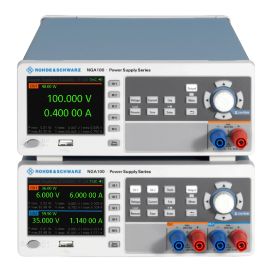
® Getting Started R&S NGA100 Instrument Tour Positioning of instrument The instrument must be positioned in a manner that allows the user to disconnect the unit from the mains at any time and without restrictions. 4.1.4.2 Rack Mounting The instrument can be installed in a 19" rack using the rack adapter R&S HZN96 (P/N 3638.7813.02). - Page 19 ® Getting Started R&S NGA100 Instrument Tour Table 4-2: Power supply models Models Number of output channels NGA101 (0 V - 35 V/6 A), NGA141 (0 V - 100 V/2 A) 1 (maximum 40 W) NGA102 (0 V - 35 V/6 A), NGA142 (0 V - 100 V/2 A) 2 (maximum 80 W) Figure 4-1: Front panel of R&S NGA100 with 2 channels 1 = Display...
-
Page 20: Rear Panel
® Getting Started R&S NGA100 Instrument Tour For detailed description on rotary knob and arrow keys, see section "Navigation Con- trols" in the User Manual. Output channels (4) Depending on the instrument models, up to two output channels are available for out- put of power to the connected load. -
Page 21: Bottom Panel
® Getting Started R&S NGA100 Instrument Tour For safety reasons, the instrument can only be operated with authorized safety sock- ets. The power cable must be plugged in before signal circuits can be connected. Never use the product if the power cable is damaged. See Chapter 4.2.2, "Switching On the Instrument", on page 22 for more information. -
Page 22: Switching On The Instrument
® Getting Started R&S NGA100 Instrument Tour yellow label sticker, make sure that the correct fuse rating is used for the mains volt- age. Figure 4-3: Bottom panel of R&S NGA100 12 = Voltage selector 13 = Voltage selector label Voltage selector (12), Voltage selector label (13) The voltage selector selects the mains voltage between 100 V, 115 V and 230 V. -
Page 23: Trying Out The Instrument
® Getting Started R&S NGA100 Trying Out the Instrument 5. Once verified, insert the fuses into each groove of the fuse holder. 6. Return the fuse holder to its position in the panel. To switch on the instrument: 1. Connect the power cable to the AC power connector on the rear panel of the R&S NGA100. -
Page 24: Activating The Channels Output
® Getting Started R&S NGA100 Maintenance and Support Alternatively: 1. Press [Voltage] or [Current] key on the front panel. 2. For the two-channel R&S NGA100, press the desired channel key to activate the respective voltage or current limit setting of that channel. The value on the respec- tive channel becomes editable and is positioned by a blue cursor. -
Page 25: Contacting Customer Support
® Getting Started R&S NGA100 Maintenance and Support Clean the outer case of the instrument at regular intervals, using a soft, lint-free dust cloth. Instrument damage caused by cleaning agents Use a dry, lint-free cloth to clean the product. When cleaning, keep in mind that the casing is not waterproof. -
Page 26: Operating Basics
® Operating Basics R&S NGA100 Display Overview 5 Operating Basics 5.1 Display Overview The following displays the screen layout of R&S NGA100. It shows the output voltage, current level and status bar information of the instrument. Figure 5-1: Screen layout of R&S NGA100 for two-channel and single channel display 1 = Device status bar 2 = Channel status bar 3 = Channel display area... -
Page 27: Channel Display Area
® Operating Basics R&S NGA100 Display Overview Function Description DIO:xxxx Digital Trigger I/O (Digital Trigger I/O option NGA-K103 must be installed). The "xxxx" refers to I/O status for DIO1, DIO2, DIO3, DIO4. If in use, the icon is highlighted in green. If enabled, the icon is highlighted in white. -
Page 28: Front Panel Keys
® Operating Basics R&S NGA100 Front Panel Keys Figure 5-2: Channel display area for one-channel model 1 = Output voltage displays in volt. The display resolution for voltage is three digits after the decimal point 2 = Output current displays in ampere. The display resolution for current is five digits after the decimal point 3 = Channel history information displaying the historical maximum and minimum channel information (P min, P max, V min, V max, I min and I max) Operating mode... -
Page 29: Function Keys
® Operating Basics R&S NGA100 Front Panel Keys 5.2.1 Function Keys The keys can be categorized based on their functions. Output and channel controls Navigation keys Instrument functions Memory functions 5.2.1.1 Output and Channel Controls These keys control the channel output settings of the instrument. Function keys Description [Ch 1], [Ch 2]... -
Page 30: Navigation Keys
® Operating Basics R&S NGA100 Front Panel Keys 5.2.1.2 Navigation Keys These keys provide navigation control in the instrument. Function keys Description Enter Confirms menu selection or entry in dialog boxes. Start and stop (long press) the EasyArb function. See Chapter 6.11.1, "EasyArb", on page 52. -
Page 31: Navigation Controls
® Operating Basics R&S NGA100 Front Panel Keys Function keys Description M1 to M5 Five memory keys to save or recall instrument settings. Store Recall Saves/loads instrument settings. See Chapter 6.12, "Store and Recall", on page 55. 5.2.2 Navigation Controls Navigation and value setting are done via the rotary knob and arrow keys. -
Page 32: Live-Mode
® Operating Basics R&S NGA100 Front Panel Keys ● The up and down keys increase or decrease any kind of numeric value when in editing mode. ● Navigate through the menu or menu items in the dialog box. ● Long press on the up and down keys increase or decrease the numeric value of the menu items to maximum or minimum value in menu dialog (e.g. - Page 33 ® Operating Basics R&S NGA100 Front Panel Keys 4. Press key to return to the previous menu level or exit the menu mode if it is already at the main menu level. Alternatively, press [Menu] key to exit the menu mode from any menu level.
-
Page 34: On-Screen Keyboard
® Operating Basics R&S NGA100 On-screen Keyboard Menu Menu items Descriptions Digital IO Configures the Digital Trigger I/O settings. See Fig- 6-10. The Digital Trigger I/O option NGA-K103 must be installed for this function to be available in the instrument. Configures the USB connection. -
Page 35: Power Derating
® Operating Basics R&S NGA100 Power Derating Figure 5-6: Virtual keyboard Invoke the on-screen keyboard as follows: 1. Move the cursor to the desired input field. 2. Press [Enter] key. The on-screen keyboard appears. 3. Once on the keyboard screen, press the arrow keys or turn the rotary knob to go to the desired character. -
Page 36: Operation Modes
® Operating Basics R&S NGA100 Operation Modes Figure 5-7: Output performance graph According to the basic electrical formula for power (P) = current (I) x voltage (V), the following results for the maximum power per channel: ● NGA101, NGA141: 40.0 W for single channel ●... - Page 37 ® Operating Basics R&S NGA100 Operation Modes Figure 5-8: Current limit CC mode The current I corresponds to the current setting adjustable in the instrument. If I reaches I , the instrument switches to CC mode, i.e. the output current remains constant and limited to I even if the load increases.
-
Page 38: Instrument Functions
® Instrument Functions R&S NGA100 Setting the Channels Voltage and Current 6 Instrument Functions 6.1 Setting the Channels Voltage and Current The R&S NGA100 comes with the following instrument models: Model Voltage Current NGA101, NGA102 0 V to 35 V <= 6 V: 6A >... -
Page 39: Activating The Channel Output
® Instrument Functions R&S NGA100 Activating the Channel Output 1. Press [Voltage] or [Current] key. The previous set channel is selected. The channel font changes to blue and all the navigation controls illuminate. Selected [Voltage] or [Current] key and the channel key are also illuminated. 2. -
Page 40: Current Range
® Instrument Functions R&S NGA100 Current Range Figure 6-3: Output of Ch2 in CC mode 6.3 Current Range The "CurrentRange" dialog provides the configuration to set the measured output cur- rent range. 1. Press [Menu] key on the front panel. The main menu screen appears. -
Page 41: Remote Sense Function
® Instrument Functions R&S NGA100 Remote Sense Function To avoid oscillation in "Auto" mode, the "Low" range to "High" range switching point is at 210 mA and the "High" range to "Low" range switching point is at 170 mA. Example: The following shows the displays of current range set to "High"... -
Page 42: Channel Fusion
® Instrument Functions R&S NGA100 Channel Fusion 3. Select the required remote sense mode for selected channels. ● "EXT": The internal voltage sense relay in the instrument is switched on and the connection of remote sense wires (S+, S- ) to the input of the load become necessary. - Page 43 ® Instrument Functions R&S NGA100 Channel Fusion 3. Set the required channel fusion mode: ● "Off": Channel operates separately ● "Series": In series mode, the two terminals in the middle are used for output. There is an internal series link activated to connect channel 1 and channel 2 output.
-
Page 44: Activating Fuse
® Instrument Functions R&S NGA100 Activating Fuse Figure 6-5: Parallel mode setting and output of one-channel display See also Chapter 8.1.2, "Parallel Mode", on page 109. Note: The "Digital IO", "EasyArb", "EasyRamp" and "CurrentRange" functions are disabled in this mode. 6.6 Activating Fuse To protect a connected, sensitive output in general, the R&S NGA100 power supply includes an electronic fuse which can be switched on individually for each channel. -
Page 45: Fuse Delay, Fuse Linking
® Instrument Functions R&S NGA100 Activating Fuse Figure 6-6: Fuse indicator on respective channel 6.6.1 Fuse Delay, Fuse Linking The fuse delay and fuse linking functions provide the flexibility to handle a fuse tripped event when it occurs. When a fuse tripped event triggered, the affected channels are turned off according to the settings configured in the fuse delay and fuse linking. -
Page 46: Tracking Function
® Instrument Functions R&S NGA100 Protection 4. Configure the "Fuse Linking" setting. The R&S NGA100 provides the following options: Example for "Ch 1", the available options are as follows: ● "Ch 2": "Ch 2" is linked to "Ch 1". If "Ch 1" fuse tripped, "Ch 2" is turned off. ●... - Page 47 ® Instrument Functions R&S NGA100 Protection If protection is tripped, a red flashing OVP or OPP indicator is displayed on the respec- tive channel. See Figure 6-8. A beep is sounded if buzzer is enabled. See Figure 6-21. Figure 6-8: Indicator of OVP/OPP when tripped 1.
-
Page 48: Digital Trigger I/O
® Instrument Functions R&S NGA100 Digital Trigger I/O The available options are as follows: ● "Enabled": The channel is turned off if the measured power exceeds OPP value. ● "Disabled": Depending on models, output power is limited to maximum value of 40 W (NGA101, NGA102) or 80 W (NGA141, NGA142). - Page 49 ® Instrument Functions R&S NGA100 Digital Trigger I/O Trigger in parameters Trigger conditions Description Output Inhibit Level Selected channel [Output] is inhibited when the selected logic level is met. When the selected channel [Output] is put to inhibit state, manual or remote operation on selected channel [Output] is no longer possi- ble .
- Page 50 ® Instrument Functions R&S NGA100 Digital Trigger I/O Trigger out parameters Trigger conditions Description Critical Event Output the selected logic level when the selected critical event (OVP, OPP, OTP) occurs on the selected channel. See Chap- ter 6.8, "Protection", on page 46. EasyArb Active Output the selected logic level when the EasyArb function is running on channel 1.
-
Page 51: Data Logging
® Instrument Functions R&S NGA100 Data Logging The R&S NGA100 enabled the selected DIO interface and monitor or feedback the trigger condition on the selected channel. 9. Set the "Master Enable" to "Enabled". The "Master Enable" is the master DIO interface which activates or deactivates all the DIO interfaces. -
Page 52: Advanced Functions
® Instrument Functions R&S NGA100 Advanced Functions Figure 6-11: Log data sample 6.11 Advanced Functions The following chapters provide information about the EasyArb EasyRamp menu items found in the [Menu] key. 1. Press [Menu] key. The R&S NGA100 displays the main menu of the instrument. Chapter 5.2.3, "Menu Key", on page 32. - Page 53 ® Instrument Functions R&S NGA100 Advanced Functions LabVIEW driver The arbitrary functions in LabVIEW driver rshmc804x do not support the EasyArb fea- ture in the R&S NGA100. The R&S NGA100 series allows you to generate freely programmable waveforms which can be reproduced within the limits set by the instrument for voltage and current. 1.
-
Page 54: Easyramp
® Instrument Functions R&S NGA100 Advanced Functions Table 6-3: EasyArb input field EasyArb input field Description EasyArb mode Enable or disable the EasyArb function. If enabled, the EasyArb function is activated in Ch 1. "EasyArb function" on page 52. Data points Set the number of data points in the EasyArb table. -
Page 55: Store And Recall
® Instrument Functions R&S NGA100 Store and Recall Figure 6-14: EasyRamp dialog 2. Select the desired channel. 3. Set the selected channel to "Enabled". The R&S NGA100 enabled the EasyRamp function for the selected channel. Note: If selected channel is set disabled, corresponding output state of the selected channel is also disabled. - Page 56 ® Instrument Functions R&S NGA100 Store and Recall Auto save instrument settings Auto save of instrument settings are applied when any of the following parameters changed: ● General instrument settings ● USB connection mode ● WLAN settings – "Module" – "SSID"...
-
Page 57: Interfaces And Protocols
® Instrument Functions R&S NGA100 Interfaces and Protocols 2. Press any of the memory keys ([M1],[M2], [M3], [M4], [M5]) to store the instrument settings. The R&S NGA100 stores the instruments settings in the selected memory location. Recall instrument settings 1. Press [Store Recall] key to recall instrument settings. The R&S NGA100 displays a message in the status bar "Recall device settings: select any [Mx] key". -
Page 58: Lan Connection
® Instrument Functions R&S NGA100 Interfaces and Protocols 6.13.1.1 LAN Connection The R&S NGA100 is equipped with a network interface and can be connected to an Ethernet LAN (local area network). A LAN connection is necessary for remote control of the instrument, and for access from a computer using a web browser. Risk of network failure Before connecting the instrument to the network or configuring the network, consult your network administrator. - Page 59 ® Instrument Functions R&S NGA100 Interfaces and Protocols a) Select "Ethernet" menu item. The R&S NGA100 displays the "Ethernet" dialog. Figure 6-15: Ethernet dialog b) Select "DHCP & Auto-IP" for "IP Mode". c) Enter the "IP Address". d) Enter the "Subnet Mask". e) Enter the "Default Gateway".
-
Page 60: Wireless Lan Connection
® Instrument Functions R&S NGA100 Interfaces and Protocols 6.13.1.2 Wireless LAN Connection Risk of RF exposure When WLAN is active, a minimum separation distance of 20 cm from front panel of the instrument must be observed at all times. When WLAN is active, no operation of antenna or transmitter should be co-located with the instrument. -
Page 61: Usb Connection
® Instrument Functions R&S NGA100 Interfaces and Protocols 2. Select "Enabled" for "Module". 3. Set the "SSID" SSID - Service Set Identifier, a unique ID used for naming wireless network. 4. Set the associated password for the "SSID". 5. Select the "Connect" button. If connection is successful, the "Status"... -
Page 62: Usb Vcp
® Instrument Functions R&S NGA100 Interfaces and Protocols Figure 6-18: USB dialog 2. Set the desired "USB Mode". ● "VCP": USB virtual COM port ● "TMC": USB Test & Measurement class 3. Press [Enter] key to confirm the settings. The R&S NGA100 displays message to prompt the user to restart the instrument to apply the changes. -
Page 63: Usb Tmc
® Instrument Functions R&S NGA100 Interfaces and Protocols 6.13.2.2 USB TMC The USB Test & Measurement class (USB-TMC) is a protocol that allows GPIB-like communication via USB interfaces and is a separate instrument class of the USB spec- ification. The USB-TMC protocol supports service queries, triggers, and other GPIB- specific instructions. -
Page 64: Scpi
® Instrument Functions R&S NGA100 Interfaces and Protocols Figure 6-19: Device manager 6.13.3 SCPI SCPI (Standard Commands for Programmable Instruments) commands - messages - are used for remote control. Commands that are not taken from the SCPI standard fol- low the SCPI syntax rules. The instrument supports the SCPI version 1999. The SCPI standard is based on standard IEEE 488.2 and aims at the standardization of device- specific commands, error handling and the status registers. -
Page 65: Setting Up Remote Control Connection
® Instrument Functions R&S NGA100 Interfaces and Protocols 6.13.5 Setting Up Remote Control Connection The following shows the resource string format used when setting up a remote connec- tion via the USB interface: ● USB TMC USB0::0x0AAD:: 0x0197::5601.8002<device_variant>-<device_serial_number>:: INSTR where k02 is used for NGA101 device, k03 is used for NGA141 device, k04 is used for NGA102 device, k05 is used for NGA142 device. -
Page 66: General Instrument Settings
® Instrument Functions R&S NGA100 General Instrument Settings 6.14 General Instrument Settings The following chapters provide the general instrument information and utilities services in R&S NGA100. 1. Press [Menu] key. The R&S NGA100 displays the main menu of the instrument. Chapter 5.2.3, "Menu Key", on page 32. -
Page 67: General Instrument Settings
® Instrument Functions R&S NGA100 General Instrument Settings Device information Description "MAC Address" MAC address of the network interface. "Export OSA to USB" The open-source acknowledgment (OSA) of the R&S NGA100 can be exported to USB stick for ref- erence. 6.14.2 General Instrument Settings General instrument settings such as keypad fallback time, screen display brightness and buzzer setting are provided. -
Page 68: Reset Instrument
® Instrument Functions R&S NGA100 General Instrument Settings The R&S NGA100 displays the "License" dialog. See Figure 6-22. Figure 6-22: License dialog To install from an XML file, proceed as follows: 1. Copy the XML file containing the registered key code into the USB flash drive. 2. - Page 69 ® Instrument Functions R&S NGA100 General Instrument Settings Figure 6-23: Reset dialog The following parameters are reset to default: Parameters Default settings NGA 101, NGA 102 NGA 141, NGA 142 Voltage, current 6.000 V, 6.050 20.00 V, 2.030 A Overvoltage Protection (OVP) Measured, 36.0 V Measured, 102.0 V Status, OVP level...
-
Page 70: System Test
® Instrument Functions R&S NGA100 General Instrument Settings 6.14.5 System Test This function provides a system test to check the instrument working conditions for screen color display, key backlight, beeper and cooling fan. ► Select "System Test" menu item. The R&S NGA100 displays the "System Test" dialog. See Figure 6-24. - Page 71 ® Instrument Functions R&S NGA100 General Instrument Settings 3. Connect the USB flash drive to the USB port of the instrument and wait for ten sec- onds. 4. Press [Menu] key. The R&S NGA100 displays the main menu of the instrument. See Chapter 5.2.3, "Menu Key",...
-
Page 72: Help
® Instrument Functions R&S NGA100 General Instrument Settings 6.14.7 Help The "Help" dialog provides the internet link and QR code for the latest R&S NGA100 information. 1. Select "Help" menu item. The R&S NGA100 displays the "Help" dialog. See Figure 6-26. - Page 73 ® Instrument Functions R&S NGA100 General Instrument Settings 3. Set the required date and time accordingly. User Manual 5601.8919.02 ─ 02...
-
Page 74: Remote Control Commands
® Remote Control Commands R&S NGA100 Common Commands 7 Remote Control Commands This chapter provides the description of all remote commands available for the R&S NGA100 series. The commands are sorted according to the menu structure of the instrument. A list of commands in alphabetical order is given in the "List of Command"s at the end of this documentation. - Page 75 ® Remote Control Commands R&S NGA100 Common Commands *IDN? Identification Returns the instrument identification. Return values: <ID> "Rohde&Schwarz,<device type>,<part number>/serial num- ber>,<firmware version>" Example: Rohde&Schwarz,NGA100,5601.8002k03/100421,1.00 *OPC Operation complete Sets bit 0 in the event status register when all preceding commands have been execu- ted.
-
Page 76: System Commands
® Remote Control Commands R&S NGA100 System Commands Prevents servicing of the subsequent commands until all preceding commands have been executed and all signals have settled (see also command synchronization and *OPC). Usage: Event 7.2 System Commands The SYSTem commands perform the various system functions and configure the com- munication interface (LAN, WLAN) for the instrument. -
Page 77: System:communicate:socket:dhcp[:State]
® Remote Control Commands R&S NGA100 System Commands SYSTem:TEST:BEEPer The instrument runs the system test: Beeper Test. Usage: Event SYSTem:TEST:FANCtrl The instrument runs the system test: Fan Control Test. Usage: Event SYSTem:TEST:KEYBacklight The instrument runs the system test: Keypad Backlight Test. Usage: Event SYSTem:TEST:SCReen... -
Page 78: System:communicate:wlan[:State]
® Remote Control Commands R&S NGA100 System Commands SYSTem:COMMunicate:WLAN:DISConnect The instrument stops the connection to the predefined wireless access point. Available only if option R&S NGA-K102 is installed. Usage: Event SYSTem:COMMunicate:WLAN:IPADdress? This command queries the IP address of the device when the wireless interface works as a client. -
Page 79: Configuration Commands
® Remote Control Commands R&S NGA100 Configuration Commands 7.3 Configuration Commands The following subsystems contain the commands for channel selection, voltage and current settings for the instrument. 7.3.1 Channel Selecting The INSTrument:Select subsystem contains the commands for selecting the output channels. -
Page 80: Remote Sense Setting
® Remote Control Commands R&S NGA100 Configuration Commands Example: INSTrument:NSELect 1 Selects the output channel as Ch 1. INSTrument:NSELect? -> 1 Return the numeric channel selection. INSTrument[:SELect] <arg0> This command defines or queries the channel selection. Each channel of the power supply is considered as separate "instrument", which is required by the SCPI standard. -
Page 81: Voltage Setting
® Remote Control Commands R&S NGA100 Configuration Commands 7.3.3 Voltage Setting The SOURce:VOLTage subsystem contains the commands for setting the voltage of the output channels. The default unit is V. Example: Configuring the output voltage This example contains all commands to configure and query the output voltage. // ************************************************ // Select the channel // ************************************************... -
Page 82: Current Setting
® Remote Control Commands R&S NGA100 Configuration Commands Example: VOLT 10 Set the voltage value to 10 V. VOLT? -> 10 Return the voltage value of the selected channel. 7.3.4 Current Setting The SOURce:CURRent subsystem contains the commands for setting the current limit of the output channels. -
Page 83: Combined Setting Of Voltage And Current Setting
® Remote Control Commands R&S NGA100 Configuration Commands [SOURce:]CURRent:RANGe <arg0> Sets or queries the current range of the selected channel. Parameters: <arg0> AUTO | HIGH | LOW AUTO The measured output current is displayed in the following: - "A" with 10 μA resolution for current above 200 mA - "mA"... -
Page 84: Output Setting
® Remote Control Commands R&S NGA100 Configuration Commands Example: INST OUT1 APPLY "6,2" Set channel 1 to output 6 V and 2 A. APPLY? -> 6, 2 Return voltage and current value of the selected channel. 7.3.6 Output Setting The OUTPut subsystem contains the commands for activating the output channels. Example: Activating the channels You can activate a selected channel and turn on or off the outputs either individually or all outputs simultaneously. -
Page 85: Output:fusion
® Remote Control Commands R&S NGA100 Configuration Commands ON | 1 Output state will be turned on. OFF | 0 Output state will be turned off. *RST: OFF | 0 Example: INST OUT1 OUTP ON Ch 1 and output state will be activated; i.e. Ch 1 and Output key on the front panel will be illuminated. -
Page 86: Output:mode
® Remote Control Commands R&S NGA100 Configuration Commands Example: INST OUT1 OUTP:SEL ON Volt 12 Curr 0.1 Ch 1 is activated. INST OUT2 OUTP:SEL ON Volt 12 Curr 0.2 Ch 2 is activated. OUTP:GEN ON Ch 1 and Ch 2 and Output state are activated. OUTP:GEN? ->... -
Page 87: Fuse Setting
® Remote Control Commands R&S NGA100 Configuration Commands Example: INST OUT1 OUTP:SEL ON Ch 1 is activated. OUTP:SEL? -> 1 Return the state of the selected channel. OTP:TRIPped? Queries the overtemperature protection (OTP) tripped state of the previous selected channel. It is tripped if an OTP event occurs. - Page 88 ® Remote Control Commands R&S NGA100 Configuration Commands Example: Configuring fuses This example contains all commands to configure and query the fuse states and set- tings. // ************************************************ // Activate a fuse // ************************************************ INST OUT1 // selects a channel and activates the overcurrent protection FUSE 1 // queries the state of the overcurrent protection in the selected channel FUSE?
- Page 89 ® Remote Control Commands R&S NGA100 Configuration Commands FUSE:LINK 2 // queries the combined overcurrent protection of the selected channel FUSE:LINK? 2 // response 1 // ************************************************ // Unlink linked overcurrent protection // ************************************************ FUSE:UNLink 2 // queries the combined overcurrent protection of the selected channel FUSE:LINK? 2 // response 0 FUSE:DELay <Delay>...
- Page 90 ® Remote Control Commands R&S NGA100 Configuration Commands FUSE:TRIPped? This command queries the fuse tripped of the previous selected channel. Return values: <arg0> Fuse is tripped. Fuse is not tripped. Example: INST OUT1 FUSE:TRIP? -> 0 Fuse of Ch 1 has not tripped. Usage: Query only FUSE:UNLink <arg0>...
-
Page 91: Ovp Setting
® Remote Control Commands R&S NGA100 Configuration Commands 7.3.8 OVP Setting The VOLTage:PROTection subsystem contains the commands for setting the over- voltage protection parameters for the output channels. The default unit is V. User Manual 5601.8919.02 ─ 02... - Page 92 ® Remote Control Commands R&S NGA100 Configuration Commands Example: Configuring the overvoltage protection // ************************************************ // Set the overvoltage protection value // ************************************************ INST OUT1 //activates the OVP of the previous selected channel VOLT:PROT 1 // selects a channel and sets the OVP VOLT:PROT:LEV 5 // queries the output overvoltage value of a channel VOLT:PROT:LEV?
- Page 93 ® Remote Control Commands R&S NGA100 Configuration Commands [SOURce:]VOLTage:PROTection:MODE <arg0> This command defines or queries the OVP mode for the previous selected channel. Parameters: <arg0> MEASured | PROTected MEASured The OVP switches off if the measured value exceeds the thresh- old.
-
Page 94: Opp Setting
® Remote Control Commands R&S NGA100 Configuration Commands Example: INST OUT1 VOLT:PROT ON OVP of Ch 1 is activated. VOLT:PROT? -> 1 Return the OVP state of the selected channel. [SOURce:]VOLTage:PROTection:LEVel <Voltage> This command defines or queries the OVP value of the previous selected channel. Parameters: <Voltage>... - Page 95 ® Remote Control Commands R&S NGA100 Configuration Commands Example: Configuring the overpower protection // ************************************************ // Set the overpower protection value // ************************************************ INST OUT1 //activates the OPP of the previous selected channel POW:PROT 1 // selects a channel and sets the OPP POW:PROT:LEV 5 // queries the output overvoltage value of a channel POW:PROT:LEV?
- Page 96 ® Remote Control Commands R&S NGA100 Configuration Commands Set the OPP value to maximum Default unit: W Example: INST OUT1 POW:PROT:LEV 5 Set the OPP value of channel 1 to 5 W. POW:PROT:LEV? -> 5 Return the selected channel OPP value. [SOURce:]POWer:PROTection:TRIPped? This command queries the OPP tripped status of the previous selected channel Return values:...
-
Page 97: Measurement Commands
® Remote Control Commands R&S NGA100 Advanced Operating Commands 7.4 Measurement Commands The MEASure subsystem provides commands to query the voltage and current values of a channel. MEASure[:SCALar]:CURRent[:DC]? This command queries the measured current value of the previous selected channel. Return values: <Current>... -
Page 98: Arbitrary Commands
® Remote Control Commands R&S NGA100 Advanced Operating Commands 7.5.1 Arbitrary Commands The ARBitrary subsystem contains the commands for configuring an arbitrary sequence for the output channels. Example: Configuring an arbitrary sequence This programming example generates an arbitrary sequence for a selected channel. The sequence starts at 1 V and 1 A for 1 sec, and both values are incremented each second by 1. - Page 99 ® Remote Control Commands R&S NGA100 Advanced Operating Commands Note: If the repetition is set to "0", the arbitrary waveform repeats continuously. Parameters: <Repetitions> 0..255 Example: ARB:REP 10 Set the repetition rate of the defined arbitrary waveform as 10. ARB:REP? -> 10 Return the defined repetition rate of the selected channel.
-
Page 100: Easyramp Commands
® Remote Control Commands R&S NGA100 Advanced Operating Commands ARBitrary:STOP This command stops the EasyArb waveform in channel 1 if EasyArb is running. Usage: Event 7.5.2 EasyRamp Commands The VOTage:RAMP subsystem contains the commands for configuring the ramp func- tion for the output channels. [SOURce:]VOLTage:RAMP:DURation <Time>... -
Page 101: Trigger:in:arbitrary:dio
® Remote Control Commands R&S NGA100 Advanced Operating Commands TRIGger[:ENABle]:DIO<IO> <arg0> This command sets or queries the state of the specified Digital I/O line. The state is disabled when any setting has been changed. Suffix: <IO> 1..4 Parameters: <arg0> {OFF | ON} Enable the state for Digital I/O line. -
Page 102: Trigger:in:source:dio
® Remote Control Commands R&S NGA100 Advanced Operating Commands INHibit Output state remains off as long as the TRIG IN signal is activa- ted. ARBitrary Starts the EasyArb function. If level signal is selected, the Easy- Arb function is stopped when TRIG IN signal is deactivated. *RST: TRIGger:IN:SOURce:DIO<IO>... -
Page 103: Trigger:out:condition:dio
® Remote Control Commands R&S NGA100 Advanced Operating Commands TRIGger:OUT:CONDition:DIO<IO> <arg0> This command sets the trigger condition of the trigger output of the specified Digital I/O line. The line triggers when the output of the specified control source is turned off or on Suffix: <IO>... -
Page 104: Trigger:out:currlevel:dio
® Remote Control Commands R&S NGA100 Advanced Operating Commands TRIGger:OUT:CURRlevel:DIO<IO> <Current> This command sets or queries the threshold current level of the trigger output of the specified Digital I/O line. Triggers when output current level exceeds or equals to the set level. Suffix: <IO>... -
Page 105: Data And File Management Commands
® Remote Control Commands R&S NGA100 Data and File Management Commands TRIGger:SAV <arg0> This command saves DIO settings into the respective memory locations M1-M5 Parameters: <arg0> Range: 0..4 Example: TRIG:SAV 1 Usage: Setting only 7.6 Data and File Management Commands The DATA and HCOPy subsystem contains commands for managing the files in the instrument and external USB stick. -
Page 106: Firmware Update
® Remote Control Commands R&S NGA100 Firmware Update ON | 1 Data logging function is enabled. OFF | 0 Data logging function is disabled. *RST: Example: LOG ON LOG? -> 1 Data logging function is activated. DATA:DATA? <> DATA:DATA?? <> Returns the logging file data of the selected file. - Page 107 ® Remote Control Commands R&S NGA100 Firmware Update For more information, see Chapter 6.14.6, "Updating the Firmware", on page 70. Parameters: <arg0> Example: DIAGnostic:SERVice:FWUP "/FRONT_USB/NGA1xx" Usage: Setting only User Manual 5601.8919.02 ─ 02...
-
Page 108: Applications
® Applications R&S NGA100 Parallel and Series Mode 8 Applications 8.1 Parallel and Series Mode It is assumed that only qualified and trained personnel service the power supplies and the connected loads. Use only the R&S NGA100 power supply series when operating the channels in a ser- ies or parallel mode to increase the output voltage and current. -
Page 109: Parallel Mode
® Applications R&S NGA100 Parallel and Series Mode Figure 8-1: Example of series connection 8.1.2 Parallel Mode If it is necessary to increase the total current, the power supply outputs must be wired in parallel. The maximum total current is the sum of the individual currents of all sour- ces connected in parallel. - Page 110 ® Applications R&S NGA100 Parallel and Series Mode Figure 8-2: Example of parallel connection Principles of operation in parallel mode Generally, a higher current will first be supplied from the channel with the higher output voltage. Once this channel reaches its power limit, the remaining current will be made available by the channel that is connected in parallel.
-
Page 111: Annex
® Additional Basics on Remote Control R&S NGA100 Messages and Command Structure Annex A Additional Basics on Remote Control A.1 Messages and Command Structure A.1.1 Messages Instrument messages are employed in the same way for all interfaces, if not indicated otherwise in the description. -
Page 112: Scpi Command Structure
® Additional Basics on Remote Control R&S NGA100 Messages and Command Structure are device-specific, however, their syntax follows SCPI rules as permitted by the standard. Instrument responses Instrument responses (response messages and service requests) are messages which the instrument sends to the controller after a query. They can contain measurement results, instrument settings and information on the instrument status. - Page 113 ® Additional Basics on Remote Control R&S NGA100 Messages and Command Structure Example: MEASure:CURRent? is equivalent to MEAS:CURR? Case-insensitivity Uppercase and lowercase notation only serves to distinguish the two forms in the man- ual, the instrument itself is case-insensitive. Optional mnemonics Some command systems permit inserting or omitting certain mnemonics in the header.
- Page 114 ® Additional Basics on Remote Control R&S NGA100 Messages and Command Structure ● Character strings ● Block data The required parameters and the allowed value range are specified in the command description. Numeric values You can enter numeric values in the following form. Values exceeding the resolution of the instrument are rounded up or down.
-
Page 115: Command Sequence And Synchronization
® Additional Basics on Remote Control R&S NGA100 Command Sequence and Synchronization " Quotation marks introduce a string and terminate it. A whitespace (ASCII-Code 0 to 9, 11 to 32 decimal, e.g. blank) separates the header from the parameters. Responses to Queries You can query each setting command by adding a question mark. -
Page 116: Preventing Overlapping Execution
® Additional Basics on Remote Control R&S NGA100 Command Sequence and Synchronization A.2.1 Preventing Overlapping Execution Table A-4: Synchronization using *OPC, *OPC? and *WAI Command Action Programming the controller ● *OPC Sets the Operation Complete bit Setting bit 0 in the ESE ●... -
Page 117: List Of Commands
® List of commands R&S NGA100 List of commands [SOURce:]CURRent:RANGe........................... 83 [SOURce:]CURRent[:LEVel][:IMMediate][:AMPLitude]..................82 [SOURce:]POWer:PROTection:CLEar......................96 [SOURce:]POWer:PROTection:LEVel......................95 [SOURce:]POWer:PROTection:TRIPped?.......................96 [SOURce:]POWer:PROTection[:STATe]......................96 [SOURce:]VOLTage:PROTection:CLEar......................94 [SOURce:]VOLTage:PROTection:LEVel......................94 [SOURce:]VOLTage:PROTection:MODE......................93 [SOURce:]VOLTage:PROTection:TRIPped?....................93 [SOURce:]VOLTage:PROTection[:STATe]......................93 [SOURce:]VOLTage:RAMP:DURation......................100 [SOURce:]VOLTage:RAMP[:STATe]......................100 [SOURce:]VOLTage:SENSe..........................80 [SOURce:]VOLTage[:LEVel][:IMMediate][:AMPLitude]..................81 *CLS.................................74 *ESE................................74 *ESR?................................74 *IDN?................................75 *OPC................................75 *OPT?................................ - Page 118 ® List of commands R&S NGA100 LOG[:STATe]..............................105 MEASure[:SCALar]:CURRent[:DC]?....................... 97 MEASure[:SCALar]:POWer?........................... 97 MEASure[:SCALar][:VOLTage][:DC]?......................97 OTP:TRIPped?..............................87 OUTPut:FUSion...............................85 OUTPut:GENeral............................. 85 OUTPut:MODE?.............................. 86 OUTPut:SELect............................... 86 OUTPut[:STATe]...............................84 SYSTem:BEEPer[:IMMediate]......................... 76 SYSTem:COMMunicate:SOCKet:DHCP[:STATe].................... 77 SYSTem:COMMunicate:SOCKet:IPADdress?....................77 SYSTem:COMMunicate:WLAN:CONNect....................... 77 SYSTem:COMMunicate:WLAN:DISConnect....................78 SYSTem:COMMunicate:WLAN:IPADdress?....................78 SYSTem:COMMunicate:WLAN:PASSword..................... 78 SYSTem:COMMunicate:WLAN:SSID......................78 SYSTem:COMMunicate:WLAN[:STATe]......................78 SYSTem:LOCal..............................76 SYSTem:OPTion?............................76 SYSTem:REMote.............................76...
-
Page 119: Index
® Index R&S NGA100 Index Activate channel output ............. 39 General instrument settings ........66, 67 Activating fuse ..............44 Buzzer ................. 67 Display ................ 67 Display brightness ............67 Key fallback time ............67 Bottom panel Keypad ................ 67 Voltage selector ............ - Page 120 ® Index R&S NGA100 Output Remote sense ............. 41 Output and channel controls ..........29 Package contents ..............16 Power derating ..............35 Protection ................46 Overpower protection (OPP) ........46 Overvoltage protection (OVP) ........46 Rear panel AC inlet with fuse holder ..........20 Digital I/O connector ...........
Need help?
Do you have a question about the R&S NGA100 and is the answer not in the manual?
Questions and answers