Table of Contents
Advertisement
Quick Links
Thank you very much for choosing the Yoshitake's product. To ensure the correct and safe use
of the product, please read this manual before use. This manual shall be kept with care for
future references.
-------The following safety symbols are used in this manual. --------
Warning
Caution
1. Specifications ···························································· 1~2
2. Dimensions and Weights ············································· 2~3
3. Operation ································································· 4~6
4.1 Specifications selection chart ····································· 7
4.2 Safety valve setting pressure chart ······························ 7
4.3 Characteristics chart ················································· 8
4.4 Nominal size selection chart ······································· 9
4.5 Nominal size selection calculation formula ···················· 10
5.1 Precautions for installation ········································ 11
5.2 Installing accessories··············································· 11
5.4 Example of piping ··················································· 13
7.1 Precautions for operation ·········································· 14
7.2 Adjustment procedures ············································ 14
8.1 Troubleshooting ··················································· 15~16
8.2 Precautions for maintenance and inspection ················· 16
8.3 Disassembly ······················································· 16~17
8.4 Precautions during reassembly ·································· 17
8.5 Exploded drawing ················································ 18~19
Model GPK-2001, GPK-2003
PRESSURE REDUCING VALVE
Installation & Operation Manual
This symbol indicates a potentially hazardous situation that, if not
avoided, could result in death or serious injury.
This symbol indicates a hazardous situation that, if not avoided, may
result in minor or moderate injury. ("Caution" may also be used to
indicate other unsafe practices or risks of property damage.)
Contents
■EPDT-098a■
Advertisement
Table of Contents

Related Manuals for Yoshitake GPK-2001


Summary of Contents for Yoshitake GPK-2001
-
Page 1: Table Of Contents
PRESSURE REDUCING VALVE Installation & Operation Manual Thank you very much for choosing the Yoshitake’s product. To ensure the correct and safe use of the product, please read this manual before use. This manual shall be kept with care for future references. -
Page 2: Specifications
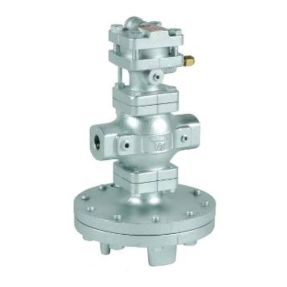
[Models] The ratio of control pressure Model Nominal pressure Connection Nominal size to setting pressure Screwed 15 ~ 50A 2.0 MPa GPK-2001 1: 1 Flanged 15 ~ 100A 1.0 MPa Screwed 15 ~ 50A 2.0 MPa GPK-2003 1: 3.5 Flanged 15 ~ 100A 1.0 MPa... -
Page 3: Dimensions And Weights
For the actual use, adjust loading air pressure suitable for the necessary set pressure. 2. Dimensions and Weights [GPK-2001] (Screwed) (Flanged) •The structure differs for nominal sizes 50A to 100A. (mm) - Page 4 [GPK-2003] (Screwed) (Flanged) •The structure differs for nominal sizes 50A to 100A. (mm) Screw (JIS Rc) Flanged (JIS 20K RF) Nominal Weight Weight Size (kg) (kg) Rc 1/2 353 170 200 17.5 353 170 200 19.0 Rc 3/4 353 170 200 17.5 353 170 200 19.5...
-
Page 5: Operation
3. Operation The pressure reducing valve reduces pressure by the throttling the valve. The valve is composed of the main valve, main valve seat, a pressure adjusting air chamber, and the main diaphragm, pilot diaphragm, and pilot valve for pressure sensing and activation. Parts name Body Main Valve... - Page 6 (2) Introducing air pressure into air chamber flexes pilot diaphragm [23] to open the pilot valve. The fluid passing through pilot valve [17] and pilot valve seat [18] enters the main diaphragm chamber [12-1] via pipes [34] and [36]. This fluid also flows to the reduced side of the body [1] through the orifice of tee [33] and pipe [35] that connects to the body.
- Page 7 (4) Reduced pressure is led to the pilot diaphragm chamber [56-1] via the sensing pipe and reduced pressure sensing port [23-1]. The pilot diaphragm receives the reduced pressure to be balanced with the air pressure. The pilot valve travel is controlled by the air pressure and pressure applied to the pilot diaphragm due to variations in reduced pressure.
-
Page 8: Nominal Size Selection Method
4. Nominal Size Selection Method 4.1 Pressure reducing valve specification selection chart Refer to the above selection chart to select the most appropriate pressure reducing valve. Find the point of intersection of inlet pressure(P ) and reduced pressure(P ). When the point of intersection is within range(A), reduce pressure in two stages. -
Page 9: Characteristics Chart
4.3 Characteristic chart (1) Flow rate characteristics chart ● Shut-off pressure rise: 0.02 MPa or less ● Offset: 10% or less of set pressure at outlet side (Minimum value: 0.0MPa) Using the nominal size selection chart, select the nominal size of 80 ~ 90% of the flow rate, considering pressure loss and heat loss of the gate valve and the strainer before and after the pressure reducing valve. -
Page 10: Nominal Size Selection Chart
4.4 Nominal size selection chart (External sensing) * Please contact us on internal sensing method. For example, take a pressure reducing valve whose inlet pressure (P ) is 0.6 MPa, reduced pressure (P ) 0.4 MPa, flow rate 600 kg/h. When determining the nominal size, find the point of intersection (A) of inlet pressure 0.6 MPa and reduced pressure 0.4 MPa. -
Page 11: Nominal Size Selection Calculation Formula
4.5 Nominal size selection calculation formula An appropriate nominal size can be calculated by obtaining Cv value for the operating conditions in question, as shown below. • Calculation formula for Cv value W: Max. steam flow rate [kg/h] : Inlet pressure [MPa・A] ... -
Page 12: Installation
5. Installation 5.1 Precautions for installation Warning (1) Since the product is heavy, securely support it using lifting devices or the like when installing. See the product weight specified in “2. Dimensions and Weights”. * Failure to follow this notice may cause falling accident of the product, resulting in bodily injury. -
Page 13: Piping Before And After The Pressure Reducing Valve
(9) Space is required above and below the center of the piping and on the conduit side for overhaul inspection, so secure the space shown in Fig. 5 when piping. (mm) Nominal size GPK-2001 GPK-2003 100A Fig.5 ■EPDT-098a■ -12-... -
Page 14: Example Of Piping
5.4 Piping example The remote pressure reducing valve can set several levels of pressure with a single pressure reducing valve depending on how the pneumatic circuit for operation is constructed, and automatic control is possible with a solenoid valve. [Standard operating circuit] [Combination operation circuit] Two sets of units are used, each of which The standard unit's air pressure reducing valve... -
Page 15: Operating Procedure
6. Operating Procedure 6.1 Precautions for operation Warning (1) Do not touch the product with bare hands directly. * Failure to follow this notice may result in scalds. (2) Before applying steam to the product, confirm that there is no risk when steam flows into the piping end and that piping joints are securely connected. -
Page 16: Maintenance Procedure
7. Maintenance Procedure 7.1 Troubleshooting (Refer to “7.5 Exploded drawing”.) Problem Cause Solution 1. Incorrect pressure is being used. 1. Correct the pressure. 2. Insufficient operating air pressure. 2. Increase the operating air pressure to the desired set pressure. 3. Screen [15] is clogged. 3. -
Page 17: Precautions For Maintenance And Inspection
1. Set the operating air pressure to no pressure. 2. Remove bolt [60] of cover [57]. 3. For GPK-2001, remove the pilot diaphragm [23], the diaphragm case [58], and pilot diaphragm plate [59]. 3. Remove pilot valve assembly using a ring spanner or socket wrench (nominal size 22). -
Page 18: Precautions During Reassembly
(3) Main diaphragm 1. Remove pipe C [36] at tee [33]. 2. Remove bolt [41] of bottom dia. case [5]. Dismount the bottom dia. case, main diaphragm [12], retainer [11], and spindle [9] (adapter [52] and retainer [11] for nominal sizes 65A to 100 A). -
Page 19: Exploded Drawing
7.5 Exploded drawing The parts name shown in the rectangle boxes are available as consumable supply. * Apply lubricant agent for heat/steam resistance (recommendation: SOLVEST No.110 paste, STT Inc.) to the bottom seal area of the pilot diaphragm and the top and bottom seal area of the main diaphragm. - Page 20 ■EPDT-098a■ -19-...
-
Page 21: Warranty Information
( e.g. in case of corrosion due to outdoor use). Fire, flood, earthquake, thunder and other natural disasters. Consumable parts such as O-ring, gasket, diaphragm and etc. Yoshitake is not liable for any damage or loss caused by malfunction or defect of the product. PDD-046f...
Need help?
Do you have a question about the GPK-2001 and is the answer not in the manual?
Questions and answers