Table of Contents
Advertisement
Quick Links
Instruction Manual
Model 4500MLP
Multilevel Vibrating Wire Piezometer
No part of this instruction manual may be reproduced, by any means, without the written consent of Geokon, Inc.
The information contained herein is believed to be accurate and reliable. However, Geokon, Inc. assumes no responsibility for
errors, omissions, or misinterpretation. The information herein is subject to change without notification.
Copyright © 2003-2017 by Geokon, Inc.
(REV I, 10/23/17)
Advertisement
Table of Contents

Related Manuals for Geokon 4500MLP


Summary of Contents for Geokon 4500MLP
- Page 1 Multilevel Vibrating Wire Piezometer No part of this instruction manual may be reproduced, by any means, without the written consent of Geokon, Inc. The information contained herein is believed to be accurate and reliable. However, Geokon, Inc. assumes no responsibility for errors, omissions, or misinterpretation.
- Page 3 Upon examination by Geokon, if the unit is found to be defective, it will be repaired or replaced at no charge. However, the WARRANTY is VOID if the unit shows evidence of having been tampered with...
-
Page 5: Table Of Contents
TABLE OF CONTENTS 1. THEORY OF OPERATION ..........................1 2. PRIOR TO INSTALLATION ..........................3 2.1 S .......................... 3 ATURATING THE ILTER TONE 2.2 S ......................3 WAGELOK ITTING NSTRUCTIONS 2.2.1 Installation ..............................3 2.2.2 Reassembly Instructions ..........................4 2.3 E ...................... - Page 6 1 - M 4500S V .................... 1 IGURE ODEL IBRATING IEZOMETER 2 - C 4500MLP ..........................2 IGURE LOSE UP OF 3 - 4500MLP S ............................2 IGURE YSTEM 4 - T ............................3 IGURE NSERTION 5 - M O’ ......................... 4...
-
Page 7: Theory Of Operation
The Model 4500MLP is designed to permit the easy installation of several piezometers inside a single borehole. It eliminates the need for alternating sand and bentonite zones by allowing the entire hole to be backfilled with bentonite grout by tremie piping it in through a grout pipe. -
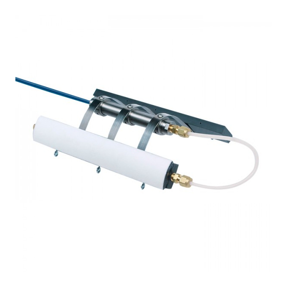
Page 8: Figure 2 - Close Up Of 4500Mlp
For the Model 4500MLP, the filter stone shown in Figure 1 is replaced by a tube leading to a much larger, curved, and porous filter stone, which is forced against the walls of the borehole by a spring mechanism. The spring mechanism can be actuated remotely after the piezometer has been lowered in its closed configuration to its desired location. -
Page 9: Prior To Installation
2. PRIOR TO INSTALLATION 2.1 Saturating the Filter Stone 1) Disconnect the Swagelok union at the transducer. 2) Immerse the whole assembly, upside down, in a bucket of water. 3) Apply a vacuum to the nylon filter tube using the large syringe supplied with the system. This removes the entrapped air from the large filter stone. -
Page 10: Reassembly Instructions
Figure 5 - Make a Mark at Six O’clock 4) While holding the fitting body steady, tighten the nut one and one-quarter turns until the mark is at the nine o’clock position. (Note: For 1/16”, 1/8”, 3/16”, and 2, 3, and 4 mm fittings, tighten the nut three-quarters of a turn until the mark is at the three o’clock position.) Figure 6 - Tighten One and One-Quarter Turns... -
Page 11: Establishing An Initial Zero Reading
4) Reassemble the fitting by inserting the tube with preswaged ferrules into the fitting until the front ferrule seats against the fitting body. Figure 8 - Ferrules Seated Against Fitting Body 5) While holding the fitting body steady, rotate the nut with a wrench to the previous position as indicated by the marks on the tube and the connector. - Page 12 To take an initial zero reading, complete the following: 1) Saturate the filter stone per the instructions in Section 2.1. 2) Allow the assembly to sit under water in a bucket for 5 to 15 minutes while the temperature stabilizes. (If possible, the temperature of the water in the bucket should be the same as the temperature of the water in the borehole.
-
Page 13: Installation
For more details on grouting, refer to “Piezometers in Fully Grouted Boreholes” by Mikkelson and Green, FMGM proceedings Oslo 2003. Copies are available from Geokon. The general rule for grouting multilevel piezometers is to mimic the strength of the surrounding soil. -
Page 14: Borehole Installation
See Sections 3.2.2 and 3.2.3. 3.2.1 The Drop Weight Method 4500MLP sensors are designed to be installed around flush coupled, one inch, Schd 80 PVC grout pipe; however, other grouting arrangements may be used. Preparing the grout pipe: 1) Connect the sections of grout pipe together and lay them out along the ground. -
Page 15: Pneumatic Cutter Method
3.2.2 Pneumatic Cutter Method 4500MLP sensors are designed to be installed around flush coupled, one inch, Schd 80 PVC grout pipe; however, other grouting arrangements may be used. The assembly is held in its closed position during installation by two nylon zip ties (supplied). -
Page 16: Figure 12 - Pneumatic Cutter Equipment
When the desired elevation is reached, the cutting tool is activated by connecting the pneumatic tube from the piezometer to a bottle of CO can be obtained locally from any welding supply outlet.) The CO bottle should have a pressure regulator that is set to a pressure of at least 2.5 MPa (350 psi), with the shutoff valve closed (Figure 12). - Page 17 The cutting tool cuts the zip ties, releasing the spring-loaded platens against the borehole walls (Figure 13). Figure 13 - 4500MLP Post-release If installed in drill casing: The sensor is lowered to the proposed elevation and the casing is pulled just above this elevation before the assembly is released.
-
Page 18: Pull-Pin Method
3.2.3 Pull-Pin Method In this method, the piezometer assembly is held in its closed position by means of a pull- pin. After the filter stone and the platen are squeezed together, the pull-pin passes through two sets of three eyebolts each, which are mounted on the filter stone and the platen. If the grout pipe is going to be removed from the borehole: The piezometer assembly must be pushed around the grout pipe, down to the desired elevation. -
Page 19: Figure 14 - Typical Multi-Piezometer Installation
When splicing, it is very important that the shield drain wires be spliced together. Splice kits recommended by Geokon incorporate casts that are placed around the splice and then filled with epoxy to waterproof the connections. When properly made, this type of splice is equal or superior to the cable itself in strength and electrical properties. -
Page 20: Lightning Protection
This is the recommended method of lightning protection. • Terminal boxes available from Geokon can be ordered with lightning protection built in. The terminal board used to make the gage connections has provision for the installation of plasma surge arrestors. -
Page 21: Taking Readings
20 hours continuously on two AA batteries. It is designed for the readout of all Geokon vibrating wire gages and transducers, and is capable of displaying the reading in either digits, frequency (Hz), period (µs), or microstrain (µε). The GK-404 also displays the temperature of the transducer (embedded thermistor) with a resolution of 0.1 °C. -
Page 22: Gk-405 Readout Box
Connecting Sensors with Bare Leads: Attach the GK-403-2 flying leads to the bare leads of a Geokon vibrating wire sensor by connecting each of the clips on the leads to the matching colors of the sensor conductors, with blue representing the shield (bare). -
Page 23: Gk-403 Readout Box (Obsolete Model)
Connecting Sensors with Bare Leads: Attach the GK-403-2 flying leads to the bare leads of a Geokon vibrating wire sensor by connecting each of the clips on the leads to the matching colors of the sensor conductors, with blue representing the shield (bare). -
Page 24: Measuring Temperatures
4.4 Measuring Temperatures All vibrating wire piezometers are equipped with a thermistor that gives a varying resistance output as the temperature changes. The white and green leads of the instrument cable are normally connected to the internal thermistor. The GK-403, GK-404, and GK-405 readout boxes will read the thermistor and display the temperature in degrees C. -
Page 25: Figure 18 - Sample Calibration Sheet
Figure 18 - Sample Calibration Sheet... -
Page 26: Data Reduction
Equation 1 - Digits Calculation For example, a piezometer reading 8000 digits corresponds to a period of 354 µs and a frequency of 2828 Hz. Note that in the above equation, the period is in seconds. Geokon readout boxes display microseconds. -
Page 27: Temperature Correction
5.2 Temperature Correction The materials used in the construction of Geokon’s vibrating wire piezometers have been carefully selected to minimize thermal effects; however, most units still have a slight temperature coefficient. Consult the calibration sheet supplied with the instrument to obtain the coefficient for the individual piezometer. -
Page 28: Barometric Correction (Required Only On Unvented Transducers)
Thus, errors may result from applying a correction that is not required. In these cases, Geokon recommends independently recording the barometric pressure changes and correlating them with the observed pressure changes in order to arrive at a correction factor. -
Page 29: Vented Piezometers
SEAL SCREW MUST BE REMOVED BEFORE THE PIEZOMETER IS PUT INTO SERVICE! The desiccant capsules are blue when fresh. They will gradually turn pink as they absorb moisture. When they have turned light pink in color, they should be replaced. Contact Geokon for replacement capsules. 5.5 Environmental Factors Since the purpose of the piezometer installation is to monitor site conditions, factors that may affect these conditions should always be observed and recorded. -
Page 30: Troubleshooting
Gages should not be opened in the field. Should difficulties arise, consult the following list of problems and possible solutions. For additional troubleshooting and support, contact Geokon. Symptom: Thermistor resistance is too high Likely, there is an open circuit. Check all connections, terminals, and plugs. If a cut is located in the cable, splice according to instructions in Section 3.3. -
Page 31: Table 3 - Sample Resistance
Vibrating Wire Sensor Lead Grid - SAMPLE VALUES Black White Green Shield ≅180Ω infinite infinite infinite ≅180Ω Black infinite infinite infinite 3000Ω at 25°C White infinite infinite infinite 3000Ω at 25°C Green infinite infinite infinite Shield infinite infinite infinite infinite Table 3 - Sample Resistance Vibrating Wire Sensor Lead Grid - SENSOR NAME/## : Black... -
Page 32: Appendix A. Specifications
1400-3500 1400-3500 1400-3500 Range Hz Table 5 - Vibrating Wire Piezometer Specifications Accuracy of Geokon test apparatus: 0.1% Contact Geokon for specific application information. Notes: Accuracy of test apparatus: 0.05% Other ranges available upon request. 0.1% FS linearity available upon request. -
Page 33: Appendix B. Thermistor Temperature Derivation
APPENDIX B. THERMISTOR TEMPERATURE DERIVATION Thermistor Type: YSI 44005, Dale #1C3001-B3, Alpha #13A3001-B3 Resistance to Temperature Equation: A+B ( LnR ) +C(LnR) -273.2 Equation 6 - Resistance to Temperature Where; T = Temperature in °C. LnR = Natural Log of Thermistor Resistance A = 1.4051 ×... -
Page 34: Appendix C. High Temperature Thermistor Linearization
APPENDIX C. HIGH TEMPERATURE THERMISTOR LINEARIZATION High Temperature Thermistor Linearization using Stein-Hart Log Equation Thermistor Type: Thermometrics BR55KA822J Resistance to Temperature Equation: A+B ( LnR ) +C(LnR) -273.2 Equation 7 - High Temperature Resistance to Temperature Where; T = Temperature in °C. LnR = Natural Log of Thermistor Resistance A = 1.02569 ×... -
Page 35: Appendix D. Improving The Accuracy Of The Calculated Pressure
APPENDIX D. IMPROVING THE ACCURACY OF THE CALCULATED PRESSURE Most vibrating wire pressure transducers are sufficiently linear (±0.2 % FS) that the use of the linear calibration factor satisfies normal requirements. However, it should be noted that the accuracy of the calibration data, which is dictated by the accuracy of the calibration apparatus, is always ±0.1 % FS.
Need help?
Do you have a question about the 4500MLP and is the answer not in the manual?
Questions and answers