
Related Manuals for Chauvin Arnoux C.A 403 ZERO GALVANOMETER


Summary of Contents for Chauvin Arnoux C.A 403 ZERO GALVANOMETER
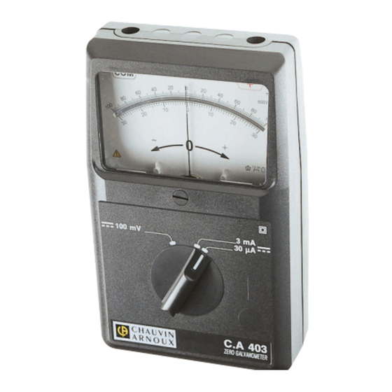
- Page 1 C.A 403 I I I I I GALVANOMÈTRE À ZÉRO CENTRAL ZERO GALVANOMETER I I I I I GALVANOMETER WITH CENTRAL ZERO F R A N C A I S Mode d'Emploi E N G L I S H User's Manual...
-
Page 2: Table Of Contents
LIRE LES INSTRUCTIONS AVANT D'UTILISER L'APPAREIL PRECAUTIONS D’EMPLOI Mettre l’appareil dans une position parfaitement stable (horizontale ou inclinée avec béquille). Vérifier que l’aiguille est bien réglée sur la graduation zéro (vis de réglage au centre de l’appareil). S’assurer que les polarités de l’appareil sont bien respectées. Si l’aiguille vient en butée, couper immédiatement l’alimentation du circuit. -
Page 3: Présentation
PRÉSENTATION Le C.A 403 réunit dans un boîtier particulièrement robuste et étanche aux poussières, les fonctions suivantes : Microampèremètre continu. Millivoltmètre continu. La simplicité et la sécurité d’emploi ont guidé la conception de cet appareil : Appareillage magnétoélectrique. Commutateur unique pour la sélection des calibres. Affichage analogique avec miroir anti-parallaxe. - Page 4 Conditions de références Température ambiante : 23 °C ± 2 °C Humidité relative : 40 à 60 % HR Position du fonctionnement : horizontale ± 1° Temps de prise de point 1,5 seconde. Dérives Température : ± 1 % / 10 °C sur 30 µA et 3 mA ±...
- Page 5 Respect des normes Matériel double isolation. IEC 61010-1 Tension d’essai de tenue diélectrique. - 5,55 kV entre le boîtier et les bornes en court-circuit. Protections électriques 1 fusible 315 mA 6,5 x 32 HPC : 380V 50kA. 1 diode TRANSIL 1500 W/1 ms protège les composants en limitant la tension aux bornes à...
-
Page 6: Remplacement Du Fusible
REMPLACEMENT DU FUSIBLE L’accès au fusible se fait en ouvrant l’arrière du boîtier. Remarques : - Le boîtier ne peut s’ouvrir que si les cordons sont déconnectés. - Dans le fond du boïtier se trouve un logement permettant d'accueillir des fusibles en réserve. - Page 7 Mesure avec shunt Brancher le C.A 403 comme indiqué sur le schéma. Placer le commutateur sur le calibre 100 mV...
-
Page 8: Pour Commander
POUR COMMANDER Référence C.A 403 ZERO GALVANOMETER ............. P01170303 Galvanomètre à zéro central livré avec un mode d’emploi. Accessoires Gaine antichoc ..................P01298016 Rechanges Jeu de 10 fusibles 0,315 A HPC (380 V - 50 kA) ....... P03297509... -
Page 9: English
ENGLISH READ THE INSTRUCTIONS BEFORE USING THE INSTRUMENT SAFETY PRECAUTIONS Put the instrument in a perfectly stable position (horizontal or at an angle on its fold-away stand). Check that the needle is correctly set to the zero mark (adjustment screw at the centre of the instrument). -
Page 10: Presentation
PRESENTATION The C.A 403 combines the following functions in a particularly sturdy and watertight case: DC microammeter DC millivoltmeter Simplicity and safety in use have guided the design of this instrument: Magneto-electric instrument Single switch for range selection Analogue display with anti-parallax mirror Single input via two safety sockets SPECIFICATIONS Ranges... - Page 11 Reference conditions Ambient temperature : 23°C ± 2°C Relative humidity : 40 to 60% RH Operating position : horizontal ± 1° Measurement time 1.5 seconds Errors Temperature : ± 1%/10°C on 30µA and 3mA ± 1.5%/10°C on 100mV Climatic conditions...
- Page 12 Adherence to standards Dual insulation equipment. IEC 61010-1 Earth test voltage. - 5.55 kV between the case and the terminals short-circuited. Electrical protection 1 fuse 315 mA 6.5 x 32 HBC: 380 V 50 kA. 1 Transil diode 1500 W/1 ms protects the components by limiting the voltage at the terminals to 10 V approx.
-
Page 13: Replacing The Fuse
REPLACING THE FUSE Access to the fuse is by opening the back of the case. Note : - The case can only be opened if the leads are disconnected. - At the back of the case, there is a place with fuses in reserve. MEASUREMENTS Without accessories Connect the C.A 403 in series in the circuit. - Page 14 With shunt Connect the C.A 403 as shown in the diagram. Place the switch on the 100mV DC range...
-
Page 15: To Order
TO ORDER Reference C.A 403 ZERO GALVANOMETER ............. P01170303 Galvanometer with central zero supplied with an User’s manual Accessories - Shockproof case ................P01298016 Spares - Set of 10 fuses 0.315 A HBC (380 V - 50 kA) ........P03297509... - Page 16 Tel: +86 21 65 21 51 96 - Fax: +86 21 65 21 61 07 SCANDINAVIA - CA Mätsystem AB Box 4501 USA - Chauvin Arnoux Inc - d.b.a AEMC Instruments SE 18304 TÄBY 200 Foxborough Blvd. - Foxborough - MA 02035...
Need help?
Do you have a question about the C.A 403 ZERO GALVANOMETER and is the answer not in the manual?
Questions and answers