
Related Manuals for Chauvin Arnoux C.A 43


Summary of Contents for Chauvin Arnoux C.A 43
- Page 1 C.A 43 ■ ■ ■ ■ ■ MESUREUR DE CHAMP LARGE BANDE FIELDMETER ■ ■ ■ ■ ■ WIDE BAND ELECTRIC FIELD METER ■ ■ ■ ■ ■ BREITBANDIGER FELDSTƒRKENMESSER FRANCAIS Mode d'Emploi ENGLISH User's Manual DEUTSCH Bedienungsanleitung...
-
Page 2: Safety Precautions
In order to keep the instrument in its accuracy class and to obtain optimum use, we advise ■ against leaving the C.A 43 permanently exposed to fields higher than 300 V/m or 100 A/m. TO ORDER Reference C.A 43 FIELDMETER 1670.02... - Page 3 CONTENTS DESCRIPTION - Case - Display PRESENTATION - General - User manual labels SPECIAL FUNCTIONS - Switching On permanent - Switching Off the sound beep - Displaying the present time - Printing the program memory - Erasing the program memory - Erasing the measurement memory - Access to several special functions MEASUREMENT MODE...
- Page 4 (cont.) DIGITAL OUTPUT REMOTE READ - Reading the measurement - Reading the state of the instrument - Reading the measurement memory - Reading the program memory - Fast reading of the memory - Example of rapid read SOUND DEMODULATION SPECIFICATIONS - Electrical specifications - Mechanical specifications MAINTENANCE...
-
Page 5: Description
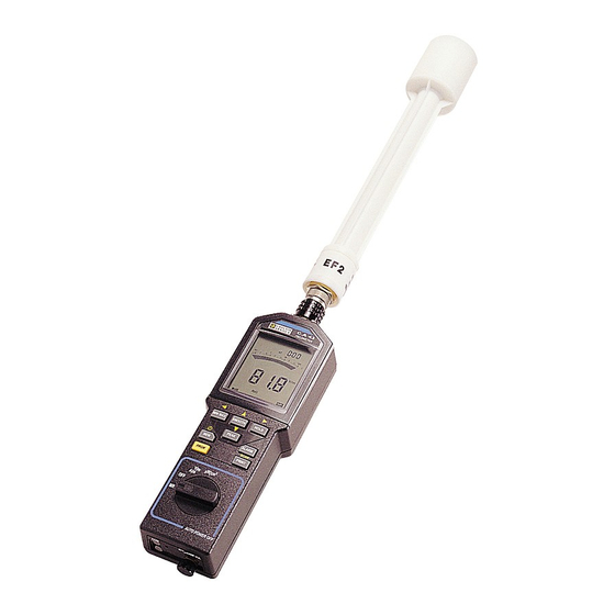
DESCRIPTION CASE 1 - Sound demodulation control 2 - Optical connector, digital link 3 - 4 position rotary switch button PRGM - Programming - Initialisation of the program memory button - Memorisation of the measurement - Display of the memory address - Display of the remaining memory capacity - Initialisation of the measurement memory button... -
Page 6: Display
11 - button ALARM - On/Off alarm detection - Selection of low and high alarms on programming - Display of the alarms on re-reading measurement memory 12 - PRINT button - Printout SCAN button - Programming print rate. DISPLAY 13 - Programming mode in operation 14 - Printout request mode 15 - Clock 16 - Cancel automatic memorisation... - Page 7 30 - Re-read measurement memory mode 31 - Memorisation of measurements 32 - Recording MIN, MAX and AVG in operation 33 - Instrument in permanent operation 34 - Digital readout of the average value 35 - Low battery indicator 36 - Digital readout of the minimum value 37 - "Beep"...
-
Page 8: Presentation
ON, and consequently its class of electromagnetic compatibility in accordance with the applicable standard. The C.A 43 is a small portable instrument that measures the electric field present in the atmosphere surrounding its measurement probe. This probe consists of an aerial combined with a high frequency detector. The wide passband of this unit enables the measurement of electrical fields from 0.1 V/m to 200 V/m for... -
Page 9: User Manual Labels
USER MANUAL LABELS Five adhesive labels are supplied with your Fieldmeter. They are simplified reminders about how to use your instrument. This information is available in five languages. Choose your label and carefully stick it to the back of your instrument. Now you will always have the information necessary to use your Fieldmeter. -
Page 10: Special Functions
SPECIAL FUNCTIONS SWITCHING ON PERMANENTLY After 10 minutes of operation without pressing a button or turning the rotary switch or reading the digital output, a battery economy system puts the instrument to sleep. This auto Off is preceded by a beep and flashing of the digital display for one minute. If you operate the instrument whilst it is flashing, the instrument will continue its active operation for a further period of 10 minutes in the selected functions and without taking into account the button pressed to wake it up. -
Page 11: Displaying The Present Time
These beeps can be suppressed if they seem too noisy to you. To do this, simultaneously press as you switch On with the rotary switch. The disappearance of the MIN MAX symbol from the screen shows that the beep is switched Off. This deactivation of the beep will be continued even after the instrument is switched Off (switch to the OFF position). - Page 12 This is done via the TxD output by a series of data consisting of three groups of four lines, giving the four values programmed for each measurement unit. At the end of this transmission the instrument returns to the measurement function and the COM symbol disappears. The presentation of the results is done in superimposed lines, each line corresponds to a programmed function.
-
Page 13: Erasing The Program Memory
When the instrument is switched On during initialisation of the program, the instrument may send false data to the serial output, symbolised by the code "error 4" (ER4). ERASING THE PROGRAM MEMORY To initialise the programme memory, press simultaneously when switching On PRGM with the rotary switch and continue to press until it disappears. -
Page 14: Measurement Mode
MEASUREMENT MODE Whatever the measurement mode, the sampling time is always 250µs. The table below summarizes the measurement times of the various modes described in this chapter. Measurement mode Symbol Digital measurement time Normal measurement 400 ms Recording (of MIN, MAX and AVG) RECORD 400 ms Smooth measurement... - Page 15 The 50Hz filter for rejection of low frequency fields is suppressed. The C.A 43 becomes sen- sitive to the power supplies of electric equipment, mains cable runs,... A first press on switches On the function and the PEAK symbol appears on the display.
- Page 16 Reading the MAX, MIN and AVG values The display of the values contained in the MAX, MIN and AVG registers is done by successive presses on MIN MAX The cycle of the display successively indicates the maximum value reached (MAX symbol), the minimum value reached (MIN symbol), the average value (AVG symbol) then the value of the current measurement and so forth.
-
Page 17: Alarm On/Off
Press again to stop recording MIN, MAX and AVG values : HOLD - The HOLD and PAUSE symbols disappear. - The digital display indicates the current measurement or the contents of the MIN, MAX or AVG registers on read mode. - The instrument is again on MIN, MAX and AVG mode but the registers have not yet been reinitialised and they contain the MIN, MAX and AVG values present before HOLD was used. - Page 18 symbols, or both, light up on the display depending on the type of threshold programmed. On the bargraph, the segments correspond to the thresholds shown in reverse contrast. When the alarms are On, a second press on switches Off the alarm function (the ALARM alarm symbols disappear).
-
Page 19: Memory Mode
(button inoperative) is emitted and the value is not stored in memory. The maximum address, 1920, is displayed. AUTOMATIC MEMORISATION The C.A 43 Fieldmeter can be used for site monitoring. With a ∆t session programmed from 1 minute to 24 hours, the min, max and average values corresponding to each session are memorised automatically. - Page 20 Note : If the value of ∆t is not programmed (symbolised by three hyphens on the ∆t programming), the memorisation does not function and the MEM symbol is not displayed. Each memorisation is dated. This date, recorded in HH MM, also corresponds to a particular memory address.
- Page 21 ▼ On read memory mode, the PEAK button changes to its second function as indicated by the symbol printed on the case. ▼ This second function allows you to decrease the different addresses of the measure- ment memory, each press moves back the read address by one. If the read address contains a manual memorisation, the display will indicate all the parameters present at the time of memorisation.
- Page 22 The alarms can be switched On or Off during the read function by simply ALARM pressing ALARM, the type of alarm programmed is shown on the display ( symbols). ▼ Each press on allows you to directly access the value beyond the next threshold.
-
Page 23: Print Mode
PRINT MODE MANUAL PRINTOUT On measurement function or memorisation function, each press on transmits PRINT ■ to the TxD optical output a series of data in the following form: <Time> <Filter> <Function> <Measurement> <Unit> Each group is separated by 1 space. The output of the five groups is ended by a carriage return and 2 line paper advance. -
Page 24: Automatic Printout
AUTOMATIC PRINTOUT When the Scanning function (printout every n minutes) is programmed, press PRINT start the measurements printing cycle with the SCAN time interval programmed. This cycle starts by printing the measurement displayed when this command is sent. The SCAN symbol remains lit on the display throughout the duration of operation of the automatic printout mode. -
Page 25: Writing A Number
In program mode (PRGM displayed), five values can be set by pressing different buttons : Press button Symbol on screen Low alarm 1st press ALARM High alarm 2nd press ALARM Memorisation session 1st press ∆t Current time 2nd press Print rate 1st press SCAN SCAN... -
Page 26: Rereading Programs
When the digit furthest to the left is active, press to display three hyphens and the previously displayed value disappears. Idem for the button when the active digit is located on the far right of the display. Note : The increase of the digit on the left gives access to tens by carrying the remainder. The validation of "- - -"... - Page 27 OPERATING PROCEDURE Connect the appropriate measurement probe to the C.A 43. The connection is made through ■ the multicontact push-pull socket located at the top of the instrument. - Position the probe in the axis of the case, - Turn the probe to align the locking system, - Push the probe in and push the ring until it locks (clicks).
-
Page 28: Ef2 Probe
3 axes without the aerial having to be moved in the 3 planes. Simply point it at the target to make the measurement. EF1 PROBE The EF1 probe supplied with the C.A 43 is anisotropic. Reception is only via the vertical polarisa- tion. Consequently, the reception diagram in the horizontal plane is circular. -
Page 29: Digital Output
DIGITAL OUTPUT The C.A 43 has a digital output. This bi-directional interface allows the instrument to communicate with external peripherals. To connect the instrument, use the optic fibre and the opto-electric adaptor. This transforms the optic signal into a usable electric signal. The optic fibre connects to the COM output of the instrument (see lug for correct position). -
Page 30: Remote Read
Transmission protocol: pseudo X ON/X OFF The transmission is done on two optic fibres : - RxD Reception of data - TxD Transmission of data This interface allows the transmission of the results of the measurement, of the content of the program memory, or measurement of the state of the instrument. - Page 31 The remote control can not start the auto print function. The remote control can not wake up the instrument which has gone to sleep after 10 minutes of operation without being manipulated. There are five types of remote read possible described in the following paragraphs. READ MEASUREMENT Codes to send to the instrument to get the value of the instantaneous measurement : - 3F Hexa, 63 Decimal...
- Page 32 The second group contains the state of the function in 3 characters : - LO AL and HI AL OFF if the alarm is not On if the alarm is On - - - if the alarm is not in service - BAT Digit corresponding to the remaining service life of the battery in %.
- Page 33 If the rotary switch is operated during the output of information, the output is interrupted. The buttons are inoperative during all the output of information. To stop the data output, set the rotary switch to OFF. READ THE MEMORY PROGRAM This function is accessible in all operating modes.
-
Page 34: Example Of Rapid Read
ROUTINE02 print:print "Retrieval of 100 points...see COM display on C.A 43" beep for N=1 to 100 delay 0.08 ì delays by 20 mS to allow for C.A 43 processing time gosub ROUTINE03 X1(N)=K next N beep print : print "display of 100 data retrieved:" : print for N=1 to 100 print "data:";X1(N) - Page 35 ì==================== S U B - P R O G R A M S ======================= ROUTINE01: ìtable of sensor 231 (taken as example) B(1)=00000:F(1)=000033:CF(1)=4.666e-2:Q(1)=00.000 B(2)=00033:F(2)=000250:CF(2)=9.953e-3:Q(2)=01.211 B(3)=00250:F(3)=000820:CF(3)=5.438e-3:Q(3)=02.340 B(4)=00820:F(4)=002640:CF(4)=3.022e-3:Q(4)=04.322 B(5)=02640:F(5)=011776:CF(5)=1.893e-3:Q(5)=07.300 B(6)=11776:F(6)=143360:CF(6)=1.294e-3:Q(6)=14.360 return ROUTINE02: print "setting up of RS232 on COM1..." open "COM1:1200,N,8,1,RS" AS #1 return ROUTINE03: print #1,chr$(34);...
-
Page 36: Sound Demodulation
SOUND DEMODULATION The demodulation function allows the amplitude modulation which may be present on the HF signal to be heard on an internal loud speaker. This detection of modulation is limited to the audible frequencies between 500 Hz and 5 kHz inclusive. The best result is obtained for fields measured between 5 V/m and 30 V/m inclusive with a modulation depth of 50% minimum. -
Page 37: Specifications
SPECIFICATIONS ELECTRICAL SPECIFICATIONS Measurement extent : ■ FUNCTION MEASUREMENT EXTENT V / m 0.1 to 199.9 µW / cm≤ 0.1 to 1999 A / m 0.1 to 19.99 Pass band: from 100kHz to 2.5GHz ■ The measurement from 100kHz to 1MHz is purely indicative. Specified measurement domain : ■... - Page 38 Variation in the operating range ■ Distortion magnitude Limit of range Magnitude distorted MAX variation Ambient 0 to 50∞C all magnitudes 0.3 % / ∞C temperature of the reading ± 0.5V/m per 10∞C Humidity 10 to 90% < 0.5 V/m no condensation magnitudes Power supply...
-
Page 39: Mechanical Specifications
- Bump resistance: 100 bumps of 10 g in the 3 axes (IEC 68-2-29) Dimensions and weight ■ - C.A 43 (without probe): 216 x 72 x 37 mm - 350 g - Measurement probe (EF1/EF2) : length: 320 mm diameter: 50 mm... -
Page 40: Maintenance
MAINTENANCE CHANGING THE BATTERY Before making a measurement, check by switching On the instrument that the battery symbol is not visible on the display. If it is, you must change the battery. The user has one minute in which to change the battery without having to reset the clock. Open the battery compartment at the back of the instrument using a coin (tool release screw). -
Page 41: Warranty
WARRANTY Unless otherwise stated, our instruments are guaranteed against any manufacturing defect, or defective parts. They do not have "Safety" specification. Our guarantee, which may not under any circumstances exceed the amount of the invoiced price, will not extend beyond repair of our instruments, returned carriage paid to our workshops. - Page 42 This figure corresponds to 80 measurements of 250µs. To get the 250µs measurement, you must therefore divide the figure obtained by 80. The measurement becomes 316352/80 = 2802.4 The measurement thus calculated must be linearised according to the following formula to get the true measurement: Measurement = Xa + b The coefficients a and b are given in the table below, they depend on the type of probe used,...
- Page 43 Each table contains 6 linearisation straight lines which are given for tables 2, 3, 4 and 5 (consult us if necessary for the other tables). The values for the start of the slope and end of slope correspond to the measurement values available on rapid interrogation of measurement.
- Page 44 Coefficients of table 04 probe EF2 first sensitivity : N∞ straight line Start Coeff. a Coeff. b 0 ct 27 cts 5.925 10e-2 27 cts 143 cts 1.207 10e-2 1.274 143 cts 572 cts 6.993 10e-3 2.000 572 cts 2544 cts 3.651 10e-3 3.911 2544 cts...
Need help?
Do you have a question about the C.A 43 and is the answer not in the manual?
Questions and answers