Cellink BIO X User Manual
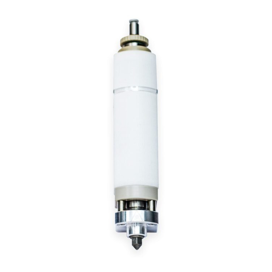
Thermoplastic printhead
Hide thumbs
Also See for BIO X:
- User manual (76 pages) ,
- Installation and quick start manual (16 pages) ,
- User manual (53 pages)
Table of Contents
Advertisement
Quick Links
Advertisement
Table of Contents

Subscribe to Our Youtube Channel
Related Manuals for Cellink BIO X


Summary of Contents for Cellink BIO X
- Page 1 BIO X Thermoplastic Printhead User Manual...
-
Page 3: Table Of Contents
Contents 1.Package contents 5.Cleaning 2.Technical specifications 6.Printing optimization 3.Safety information 7.Relevant G-code commands 3.1 BIO X system warnings 8.Frequently asked questions 3.2 Thermoplastic Printhead warnings 9.Maintenance 4.Getting started 9.1 Post-printing instructions 4.1 Unpacking and installation 9.2 Long-term maintenance 4.2 Heating the Thermoplastic Printhead Appendix A: Consumables 4.3 Recommendation: Using external air supply... -
Page 5: Package Contents
Package contents... - Page 6 01 Package contents Item Part number Quantity Thermoplastic Printhead 000000020347 Metal cartridge 000000020358 4-mm tube connector M3 (straight stainless) 000000010160 Thermoplastic Printhead top cap 000000020363 Locking ring 000000020361 Plunger 000000020362 Plunger removal tool (160 mm) 000000020373 Blue tubing (150 mm) 000000010109 Wrench 000000020537...
-
Page 7: Technical Specifications
Technical specifications... - Page 8 02 Technical specifications • Compatible with CELLINK thermoplastic cartridge. • Dimensions (height x width x depth): • With cartridge (no tubing or nozzle): 165 x 32.5 x 44 mm. • Without cartridge or nozzle: 129.5 x 32.5 x 44 mm.
- Page 9 02 Technical specifications Figure 1: Theoretical maximum build volume shown from the top and side view using the Thermoplastic Printhead (assuming a nozzle length of 7 mm). Exact build volume depends on the cartridge’s position in the printhead and the nozzle/needle used. Build volume may be lower when combining the Thermoplastic Printhead with a printhead that restricts printbox movement.
- Page 10 02 Technical specifications Table 1: Theoretical build volume based on common tip lengths. Actual volume may vary based on build plate’s thick- ness, size, shape and level, as well as on cartridge position and tightness of the nozzle. X, Y and Z are measured from the front left corner of the printbed.
-
Page 11: Safety Information
Safety information... -
Page 12: Bio X System Warnings
• Load and unload the Thermoplastic Printhead onto the BIO X printhead mounts using guidelines in the Getting Started section. Do not pull or push the printhead with excessive force while it’s loaded on the BIO X. Using excessive force risks damaging the motor and its guides. - Page 13 03 Safety information • DO NOT use a jerking motion to remove the printhead. Using a jerking motion risks hitting and damaging the HEPA filter • DO NOT touch a moving printhead. Fingers can be crushed between the printhead base and motor arm and can result in serious injury.
-
Page 15: Getting Started
Getting started... -
Page 16: Unpacking And Installation
04 Getting started NOTE: The printing parameters displayed on this manual might not be accurate for your specific protocol. For recommended parameters please consult the documentation for the bioink being used. 4.1 Unpacking and installation 1. Open the package. Remove the pre-assembled Thermoplastic Printhead. 2. - Page 17 04 Getting started 3. Assemble the Thermoplastic Printhead (Figure 3). • Place the plunger inside the metal cartridge. Attach the top cap. (Plunger use is optional.) • Insert the assembled cartridge into the Thermoplastic Printhead (Figure 3A). Twist until the cartridge is screwed into place.
- Page 18 (Figure 4B). Figure 4: Attaching the Thermoplastic Printhead to the BIO X. (A) Line up the printhead with a mount on the printbox. (B) Slide the printhead down with one hand and secure the bottom of the printhead mount with the other hand.
-
Page 19: Heating The Thermoplastic Printhead
04 Getting started 4.2 Heating the Thermoplastic Printhead NOTE: The steps under this section will test the temperature functionality of your Thermoplastic Printhead. It is only necessary to follow these steps once, after receiving your new printhead. 1. Assemble and attach the Thermoplastic Printhead (Section 4.1). 2. - Page 20 04 Getting started 4. Set the temperature of the printhead to 150 degrees Celsius. 5. Allow the printhead to heat up to 150 degrees. WARNING: Do not touch the printhead while heating. Doing so risks serious injury. 6. Once the printhead reaches 150 degrees, set the temperature to 250 degrees. 7.
-
Page 21: Recommendation: Using External Air Supply
700 kPa. 1. Connect the external air supply to the BIO X through the pneumatic connector on the back of the device. The connector requires a 4-mm air tube (Figure 6). - Page 22 04 Getting started Figure 6: External air supply inlet. A 4-mm air tube can be inserted into the BIO X using the pneumatic connector located on the back of the device.
- Page 23 04 Getting started 2. Navigate to the Utilities menu and select the Tools submenu. Select Pressure and toggle the External Pump. Toggle the External Pump setting to enable the external air supply in the Utilities menu. The system will reflect the new maximum pressure that can be set from the external air supply (Figure 7).
-
Page 24: Loading The Granulate
04 Getting started 4.4 Loading the granulate 1. If hot, allow the PH to cool to room temperature. If plunger is inserted, remove it using the plunger retrieval tool. Fill the cartridge with thermoplastic granulate. NOTE: Don’t overfill the cartridge. Too much granulate can lengthen preheating time and clog the cartridge. - Page 25 04 Getting started Figure 8: Loading the Thermoplastic Print- head with granulate.
- Page 26 04 Getting started 6. Attach the printhead to the printhead mount (Section 4.1). Navigate to the Tools menu to lower the printhead mount. Select the tool to use and tap the downward arrow (Figure 9). Once the mount is lowered, attach the air tube to the pneumatic connector on the printbox. Figure 9: (A) Attaching the Thermoplastic Printhead to the mount.
- Page 27 04 Getting started 7. Preheat the printhead to the desired temperature (Section 4.2). 8. Wait 15-20 minutes. Test the extrusion of the melted granulate using the Tools submenu (Figure 10). 9. If the granulate is not extruding, adjust the temperature and pressure. 10.
-
Page 28: Your First Bioprint
04 Getting started 4.5 Your first bioprint 1. Prepare the printhead and granulate (Sections 4.1 and 4.4). Set up the external air supply if needed (Section 4.3). 2. Ensure that the thermoplastic granulate is melted and flowing normally (Section 4.4). 3. - Page 29 04 Getting started 4. Select an STL file (extension .stl) from the Model menu and proceed to the next menu (Figure 12). Figure 12: Selecting an STL file from the Model menu.
- Page 30 04 Getting started 5. Select a surface to print on. Proceed to the next menu (Figure 13). Figure 13: Select a print surface from the Surface menu.
- Page 31 04 Getting started 6. Select printhead positions that have been set up. 7. Ensure that Thermoplastic is selected under Tool type. Enter the printing parameters for the printhead (Figure 14). Proceed to the Layers menu. Parameters necessary for the Thermoplastic Printhead include: •...
- Page 32 04 Getting started 8. Assign the enabled printhead to the respective layer characteristics and proceed to the next menu (Figure 15). Figure 15: Layer menu. Toolheads can be assigned to respective print areas such as perimeter, infill and support. You can select the infill pattern and density and preview the layers.
- Page 33 04 Getting started 9. Select the Drop button to prime the nozzle/needle and test bioink flow (Figure 16). Clean the extrusion tip using a metal tool, such as tweezers. Press Print to proceed to the calibration page. Figure 16: Print menu. You can preview your printing parameters and test the pressure.
- Page 34 04 Getting started 10. Select Calibrate (Figure 17). Bring the tip of the nozzle/needle to your desired starting position. We recommend making sure that the tip touches the surface of your printing substrate. 11. Start the bioprinting process (Figure 17). Figure 17: Bioprint menu.
-
Page 35: Refilling
04 Getting started 4.6 Refilling CAUTION: Printhead may be very hot when changing material or refilling. If you used the plunger: 1. Remove the printhead from the printhead mount. To prevent motor damage, use one hand to secure the top of the printhead mount while sliding the printhead upward with the other hand. 2. - Page 36 04 Getting started If you did not use the plunger: 1. Unscrew the top cap. There is no need to remove printhead from its mount. 2. Let the printhead and metal cartridge cool down before loading more granulates, or use a funnel to prevent material from melting on the sides of the cartridge.
-
Page 37: Cleaning
Cleaning... - Page 38 05 Cleaning 1. Remove the printhead from the printhead mount. To prevent motor damage, use one hand to secure the top of the printhead mount while sliding the printhead upward with the other hand. 2. Remove the nozzle with the wrench while the printhead is still warm. 3.
- Page 39 05 Cleaning 11. Use the wrench to loosen the cartridge. 12. Disable the temperature using the Tools option on the Utilities menu. 13. Wait for the Thermoplastic Printhead to cool to room temperature. 14. Remove the cartridge once cooled. 15. Clean the nozzle, cartridge and plunger using a solvent compatible with stainless steel. Perform the following steps in a fume hood using protective equipment: •...
-
Page 41: Printing Optimization
Printing optimization... - Page 42 Please contact support@cellink.com so we can provide you with the proper solution regarding an external pump or using your building’s air supply. It is necessary to ensure that a secondary regulator...
- Page 43 06 Printing optimization spikes beyond the recommended limit of 700 kPa. After loading the thermoplastic granulates into the cartridge, use the plunger to compact the material to improve melting and material extrusion. Please refer to the material guides for more detailed instructions. We recommend letting the printhead and material preheat for at least 15 minutes to ensure that the thermoplastic has melted completely prior to printing.
-
Page 45: Relevant G-Code Commands
Relevant G-code commands... - Page 46 G7 is the relative move command. The values for the X and Y parameters are the coordinates (in mm) directing where to move relative to the current position. E tells the BIO X to open the valve for extrusion. F is the speed of the printhead in mm/min.
- Page 47 07 Relevant G-code commands G92 Xnnn Ynnn Znnn G92 sets the current position of the printhead to the specified X, Y and Z coordinates. If no parameters are given, the position is assumed to be 0, 0, 0 (this will also change the Z position). Switch to printhead (x).
-
Page 49: Frequently Asked Questions
Frequently asked questions... - Page 50 08 Frequently asked questions • What do the LED colors indicate? The printhead LED will change depending on its status. When the printhead is first mounted, the light will turn white to indicate that it is initializing. Once it is recognized, the LED will turn blue.
- Page 51 08 Frequently asked questions If there is a sound of air coming out of the nozzle, or the molten thermoplastic is sputtering out of the nozzle, the cartridge may be empty. It is also possible that the granulate is not molten enough. Check the cartridge and refill it if necessary.
- Page 52 08 Frequently asked questions • My needle is dragging through my printed structure during travel movements. A low layer height or print speed can result in thicker-than-expected filaments that the needle subsequently touches when moving. Try raising the parameters to compensate. •...
- Page 53 08 Frequently asked questions increasing the pause time by 15 seconds for each layer after the first three layers. • Why is my material dripping out of the cartridge with no pressure? The weight of the plunger is enough to extrude low viscosity thermoplastics. Remove the plunger and/or switch the nozzle to a smaller diameter.
-
Page 55: Maintenance
Maintenance... -
Page 56: Post-Printing Instructions
09 Maintenance 9.1 Post-printing instructions • If enabled, turn off temperature regulation using the Utilities menu. • Wait until the Thermoplastic Printhead cools down. • Remove the air line from the printhead inlet. • Remove the printhead from the system. 9.2 Long-term maintenance •... -
Page 57: Appendix A: Consumables
Appendix A: Consumables... - Page 58 Appendix A: Consumables Table 2: Compatible nozzles. PART NUM- TYPE COLOR INNER DIAM- LENGTH ETER (MM) (INCHES) 000000020619 Metal nozzle 000000020620 Metal nozzle 000000020420 Metal nozzle 000000020621 Metal nozzle 000000020622 Metal nozzle Table 3: Compatible cartridges and accessories. PART NUMBER DESCRIPTION QUANTITY 000000020358...
-
Page 59: Support Information
Support information • Official site: www.cellink.com • Contact: support@cellink.com • Contact: sales@cellink.com • Web store: www.cellink.com/store Store Sales Support Official site... - Page 60 www.cellink.com...
Need help?
Do you have a question about the BIO X and is the answer not in the manual?
Questions and answers