Table of Contents
Advertisement
Advertisement
Table of Contents

Subscribe to Our Youtube Channel
Related Manuals for Cellink BIO X6


Summary of Contents for Cellink BIO X6
- Page 1 BIO X6 User Manual BIO X6 User Manual v. 1.0...
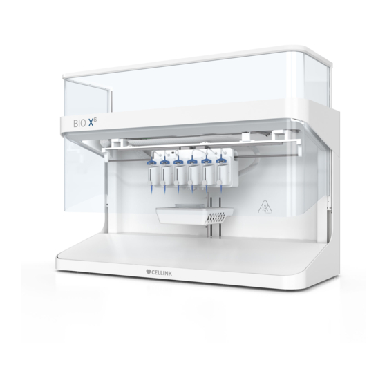
- Page 2 BIO X6 is ready to overcome the most complex bioprinting challenges. This manual is your guide to getting started with the BIO X6. Read the manual in its entirety before using the BIO X6.
-
Page 3: Table Of Contents
Product overview Technical specifications Getting started Unpacking the BIO X6 Contents of the box Setting up the BIO X6 Starting the BIO X6 for the first time Calibration trimming Bioprinting with the BIO X6 Mounting of bioprinting equipment 4.1.1 Printheads 4.1.2... - Page 4 Calibration and Auto Bed Levelling (ABL) 4.5.7 Printing droplets with multiple heads Manual photocrosslinking – Droplet 4.5.8 BIO X6 Protocol Parameter Guidelines 4.6.1 BIO X6 Protocol Parameter Guidelines Protocol aim 4.6.2 Background 4.6.3 Parameters in DNA Studio 4.6.4 Helpful hints and troubleshooting...
- Page 5 Equipment for coaxial printing Maintenance 10.1 Maintenance plan 10.2 Troubleshooting 10.2.1 Software update 10.2.2 Troubleshooting quick guide 10.3 Manually cleaning or sterilizing the BIO X6 Terms and conditions 11.1 General terms and conditions 11.1.1 Orders and supplies etc. 11.1.2 Payment 11.1.3 Service 11.1.4...
- Page 6 Trademarks and other intellectual property rights 11.1.11 Permitted use of the products 11.1.12 Limitation of liability 11.1.13 Force majeure 11.1.14 Confidentiality 11.1.15 Miscellaneous 11.2 End-user license agreement BIO X6 11.2.1 License 11.2.2 Authorized users 11.2.3 Reservation of rights 11.2.4 Updates or revisions 11.2.5 Trademarks 11.2.6...
- Page 7 12.3 CELLINK Thermoplastic Printhead 12.3.1 Getting started 12.3.2 Printhead overview 12.3.3 Assembling the Thermoplastic Printhead BIO X6 User Manual v. 1.0...
- Page 8 Safety BIO X6 User Manual v. 1.0...
-
Page 9: Safety Information
This symbol indicates risk of injury or equipment damage. This symbol indicates a heated surface. The BIO X6 has heated surfaces that may cause personal injury or equipment damage if not treated with care. A physical symbol labels these surfaces on the BIO X6, and the symbol appears on the BIO X6 touchscreen when the print chamber is heated. -
Page 10: General Safety Information
1.1 General safety information If the BIO X6 acts in a way that is not described in this manual, turn it off and contact CELLINK. Use the BIO X6 for its intended purposes only. Do not modify its instruments, subcomponents, or accessories. Do not open or disassemble the BIO X6 or attempt any service other than those described in the manual. -
Page 11: Unpacking, Lifting, And Carrying
1.2 Unpacking, lifting, and carrying Read how to safely unpack and setup the BIO X6 in Section 3 of this manual. The BIO X6 is heavy (approximately 50 kg/110 lbs.). Never attempt to lift alone. Always use a minimum of two people to unpack and move the machine. -
Page 12: Hazardous Materials
• Any metal sinks • The frame of the BIO X6 when connected to a grounded power outlet, as well as any exposed screws, including the screws on the left-side door hinges 1.6.2 Clothing Avoid charging yourself to ensure ESD protection. Wear clothes made from cotton when appropriate. -
Page 13: Compliance
1.7 Compliance By using the BIO X6, you agree to the terms stated here and, in the warranty (see Warranty). Except for the express warranty set forth in the warranty information and in our software, license terms as applicable, all equipment and software provided hereunder are provided “as is”, and CELLINK makes no warranty as to its use or performance. - Page 14 Specifications BIO X6 User Manual v. 1.0...
-
Page 15: Specifications
2 Specifications 2.1 Product overview Figure 1 Front view of BIO X6 Clean Chamber unit Printbox (printhead mount 1-6) Photocuring LED 1-4 Printbed UV protective door Docking station BIO X6 User Manual v. 1.0... - Page 16 Figure 2 Back view of BIO X6 Power switch Fuse Power socket Pneumatic port USB port Ethernet port BIO X6 User Manual v. 1.0...
-
Page 17: Technical Specifications
Calibration options: X-Y-Z axis, Manual (mechanic based) X-Y-Z axis, Automatic (touchless based) Printbed, automatic bed levelling ABL (mechanic based) Resolution μm Theoretical resolution XY: 1 μm Theoretical layer resolution Z: 0 μm Software Resolution XYZ: BIO X6 User Manual v. 1.0... - Page 18 Pneumatic printhead: 30–65°C Temperature-controlled Printhead: 4–65°C (lowest temperature 17°C below chamber temperature) Thermoplastic Printhead: 50–250°C Supported file formats: G-code, stl, amf, 3mf, obj. User interface: Desktop application DNA Studio Connectivity: USB Storage, Ethernet connection BIO X6 User Manual v. 1.0...
- Page 19 Getting started BIO X6 User Manual v. 1.0...
-
Page 20: Getting Started
Doing so can lead to personal injury and equipment damage. Always lift the BIO X6 from the underside. The BIO X6 is heavy (approximately 50 kg/110 lbs). Never attempt to lift it alone. Always use a minimum of two people to unpack and move the BIO X6. - Page 21 Figure 4 Overview of equipment included with the BIO X6 7. Remove the docking station and the tablet from the compartment behind the BIO X6. 8. With the assistance of a second person, lift the BIO X6 from the underside and place it on the table.
-
Page 22: Contents Of The Box
[1x] Tablet stand adapter US if applicable ................Box Bioink kit contains: [1x] Cell-mixer .......................... [1x] CELLINK Bioink Sterile (3pcs) ..................[1x] Crosslinking solution………….................... [1x] Sterile needle kit …………....................[1x] SDS CELLINK Bioink safety data sheet………………………………........BIO X6 User Manual v. 1.0... - Page 23 [ x] M x Hex . Screw …………..................[1x] Hex 1.3 L-key …………..................... Box gift contains: [1x] Kitchen timer …………..................... [ x] Calculator …………......................[ x] Candy pack …………....................... [ x] Sticky note …………......................[ x] Kitchen timer …………...................... BIO X6 User Manual v. 1.0...
-
Page 24: Setting Up The Bio X6
The BIO X6 has an internal air supply capable of providing up to 200 kPa to the printheads. To use higher pressure, connect an external air supply to the back of the BIO X6 (see 2.1 Product overview). -
Page 25: Starting The Bio X6 For The First Time
3.4 Starting the BIO X6 for the first time When you start the BIO X6 for the first time, you are taken to the home screen. Figure 5 Home screen of BIO X6 1. Printing Utilities menu with advanced settings and troubleshooting functions 2. - Page 26 15. Recent print protocols: This section shows shortcuts to the last 18 protocols. Protocols are saved with the file extension .biox. 16. Open print protocols: Tap to access all .biox protocols stored in your system. BIO X6 User Manual v. 1.0...
-
Page 27: Calibration Trimming
3.5 Calibration trimming The BIO X6 has a protocol for running an auto calibration trimming procedure. This procedure consists of an automatic calibration followed by a manual calibration of all six printheads. The whole process takes about 15 minutes. Auto calibration trimming must be performed before using the system for the first time, to ensure that the automatic calibration is correctly aligned. - Page 28 If you are working with a specific nozzle/needle gauge, and the autocalibration trimming has been performed using another nozzle/needle gauge, repeat the procedure with the new nozzle/needle to improve the accuracy of the autocalibration. BIO X6 User Manual v. 1.0...
- Page 29 Bioprinting BIO X6 User Manual v. 1.0...
-
Page 30: Bioprinting With The Bio X6
2. Press it until you feel the magnet snap into place. A white light turns on when the BIO X6 detects the presence of a printhead. If the printhead is correctly mounted in the BIO X6, the light changes to blue. - Page 31 1. Intelligent printhead connector: This connector connects the intelligent printhead to the BIO X6. 2. Magnet: The magnets hold the printhead in place. 3. Pressure connector: The pressure connector delivers compressed air to the pneumatic printheads. BIO X6 User Manual v. 1.0...
-
Page 32: Printbed
Use the spring-loaded arms to securely fasten the print surface on the printbed according to the illustration below. Turn the arms to the sides when using a well plate. Ensure the outer dimensions of the well plate are 128 x 85 mm. Figure 9 Printbed 1. Spring-loaded arms BIO X6 User Manual v. 1.0... -
Page 33: Sterilizing The Printing Chamber
4.2 Sterilizing the printing chamber The BIO X6 has a UV sterilization system to ensure a sterile environment. The system sterilizes the print chamber, and the Clean Chamber™ Technology maintains the system’s sterility. Do not look directly at UV light and do not expose your skin to UV light. UV light can cause serious personal injury. -
Page 34: Printing Utilities Menu
On the home screen, tap to show the left side menu. Figure 10 Printing utilities menu on the home screen Printing Utilities: Tap to access the Printing Utilities menu with advanced settings and troubleshooting functions. BIO X6 User Manual v. 1.0... -
Page 35: Connect Tab
4.3.1 Connect tab Use this tab to connect your tablet or computer wirelessly to the BIO X6. The Utilities menu will not be enabled unless you are connected to a bioprinter. Figure 11 Overview of the Connect tab 1. Search for bioprinter on network: Tap to search for a bioprinter connected to the same Wi-Fi network as the tablet/computer you are using. -
Page 36: Printer Tab
4.3.2 Printer tab Use this tab to enable special features for experimental purposes. All the changes to the printer settings done here are applied immediately to the BIO X6. Figure 12 Overview of the Printer tab 1. Sensors: Display output data for customer support. CELLINK uses this tab to perform sensor testing. - Page 37 3. Enable Clean Chamber fan: Tap to turn the Clean Chamber fan on or off. 4. Sterilize chamber: Tap to initiate the Sterilize chamber protocol. 5. Printbed temperature control: Tap to enable temperature control on the printbed. If disabled, the printbed will be kept at room temperature. BIO X6 User Manual v. 1.0...
-
Page 38: Printhead Configuration Tab
4. Print speed: Tap to set the print speed. 5. Temperature: Tap to enable or disable temperature control on the printhead. BIO X6 User Manual v. 1.0... - Page 39 6. Flow delay: Tap to set the flow delay. 7. External pressure pump: Tap to indicate if an external pressure pump is connected to the BIO X 6. BIO X6 User Manual v. 1.0...
-
Page 40: Move Tab
6. Tap to move the toolhead to the print position. 4.3.5 Machine calibration tab Use this tab to perform a calibration trimming procedure when setting up your printer and after updating the software or performing a significant hardware change (see Calibration trimming). BIO X6 User Manual v. 1.0... - Page 41 The calibration is stored and remembered to perform automatic calibration in the Bioprint menu. BIO X6 User Manual v. 1.0...
-
Page 42: Camera Tab
5, 1 and 0.1 mm. 5. Save photos to: Tap to select a folder to which the captured photos are to be saved. 6. Camera light: Tap to adjust the camera light. BIO X6 User Manual v. 1.0... - Page 43 4. Intensity: Use the slider to set the intensity to a value between 0 and 100%. 5. Timer: Tap to set the timer for photocrosslinking (0.1 s to 600 s). 6. Start: Tap to start the photocrosslinking. BIO X6 User Manual v. 1.0...
- Page 44 4.3.8 Update Printer tab Download the latest software version from dna.cellink.com and save it to a USB flash drive. Insert the USB flash drive into the BIO X6. Figure 18 Overview of the Update Printer tab In the Utilities menu, go to Update Printer to access the update.
- Page 45 Use this tab to view contact information for customer support, the software version, and the printer and software licenses. Figure 19 Overview of the About tab 1. License: Tap to show the printer and software license. BIO X6 User Manual v. 1.0...
- Page 46 4.4 Bioprinting from a 3D model On the home screen, tap Model to start a new bioprinting process using a 3D model. The BIO X6 guides you through the process of setting up your bioprint. Figure 20 Model option on the home screen...
- Page 47 3. Select a number to choose a well plate to print in. 4. Select a vendor for the well plate you are using. This feature enables the BIO X6 to know the precise dimensions of the well plate, which may vary slightly depending on the vendor (1.
- Page 48 Figure 22 Custom well plate option BIO X6 User Manual v. 1.0...
- Page 49 1. Insert a USB flash drive containing your 3D model and any custom profiles you would like to use into any of the USB ports on the back of the tablet docking station BIO X6 Tap Open… to select the model you wish to bioprint from your files.
- Page 50 Tap the trash bin to delete the selected file. Any modifications can be reset or previewed in the center of any print surface. Figure 25 Transform model option 3. Well selection: Tap to select which wells to print in and in what order (see screenshot below). BIO X6 User Manual v. 1.0...
- Page 51 8. Isometric views: Tap to choose between different options: perspective, top view, side view. This helps you visualize with more detail the models to print and check for issues on the model or with the slice. BIO X6 User Manual v. 1.0...
- Page 52 4.4.3 Layer settings Modify options to define the layers of the 3D model and how the BIO X6 should bioprint the selected model. Use the predefined settings or create custom settings. Figure 27 Overview of the Layers step 1. Layer height: Specify the thickness of each layer in mm. CELLINK advises to set the layer height to 80-100% of the nozzle diameter.
- Page 53 You will need to designate a printhead for printing this structure support. 12. Preview slider: Drag this to select which layer to preview. The total number of layers may vary depending on the selected layer height (1). BIO X6 User Manual v. 1.0...
- Page 54 90 degrees from layer to layer. This pattern is suitable for fibers and striated tissues. It can also generate constructs that contain porosity to allow diffusion of nutrients or filling with other bioinks or materials. BIO X6 User Manual v. 1.0...
- Page 55 The pattern is similar in structure and orientation to the rectilinear pattern. This is most applicable for tissues such as skin, ligament, muscle, tendon, and others where elasticity is important. BIO X6 User Manual v. 1.0...
- Page 56 4.4.4 Printhead settings The BIO X6 can use up to six different printheads in a single bioprinting process. Depending on the printhead you are using, different settings are required for configuration. For general information about the printheads, see Printhead manuals. Further details are outlined in the separate printhead manuals.
- Page 57 12. Toolhead bar: Displays the toolheads indicated to be involved in the bioprinting process. Each tool is given a color for identifying the layers it must print of the 3D model in the preview (11). BIO X6 User Manual v. 1.0...
- Page 58 Go to print. The fan will then be kept on or turned off, depending on your choice). 3. Lights: Tap to enable or disable the interior lights of the BIO X6. If enabled, you can drag to select the light intensity.
- Page 59 7. Travel settings: Tap to change the speed of the travelling movement. This feature is mainly for speeding up prints by performing the non-print movements faster, for example when the printhead moves from one well to another. BIO X6 User Manual v. 1.0...
- Page 60 7. Tool 6: Displays an illustration of the tool 6 and shows its settings. 8. Search for printer: This button indicates that the BIO X6 is not connected with the tablet/computer on which the bioprinting process is being set up. If not connected, you cannot proceed with the bioprinting process.
- Page 61 If not connected, you cannot proceed with the bioprinting process. 16. Go to Print: Tap to proceed with the bioprinting process. After checking all the settings, proceed with the bioprinting process, tap Go to Print and continue with the calibration settings. BIO X6 User Manual v. 1.0...
- Page 62 5. Start print: Tap to start print. This button is only enabled once the calibration protocol is complete. Tap Calibrate to calibrate the printheads and the printbed. There are three calibration options: Automatic calibration, Manual calibration, and Automatic bed levelling (see screenshot below). BIO X6 User Manual v. 1.0...
- Page 63 The Automatic calibration protocol is not compatible with the HD Camera toolhead, Photocuring toolhead, Thermoplastic Printhead or EMD Printhead. If one of these toolheads is connected to the BIO X6 when performing Automatic calibration, you can choose to calibrate them manually.
- Page 64 (Surface: Home the printer axes and return to absolute zero position). 2. Done: Tap to proceed with the bioprinting process. This button will only be enabled once the calibration has been successfully completed. 3. Abort: Tap to abort the calibration. BIO X6 User Manual v. 1.0...
- Page 65 7. Camera icon: Tap to review and edit the camera settings. This option is only available the Camera tool is connected to the BIO X6. 8. Start print: Tap to start the bioprinting process. This button will only be enabled once the calibration protocol is complete.
- Page 66 Tip: Before calibration, unscrew the cartridge locking screw to avoid damaging the nozzle if accidentally moving the printbed too high. Re-tighten it before saving the calibration. The first step of the instructions to follow vary depending on what surface you use: BIO X6 User Manual v. 1.0...
- Page 67 Petri dish Figure 40 Manual calibration – Petri dish Well plate Figure 41 Manual calibration – well plate Glass slide BIO X6 User Manual v. 1.0...
- Page 68 Figure 42 Manual calibration – glass slide BIO X6 User Manual v. 1.0...
- Page 69 You can repeat the same procedure to calibrate all the printheads in your system by using the same point on the selected surface as a reference. Note: Manual calibration works with all printhead types and all needles and nozzles. BIO X6 User Manual v. 1.0...
- Page 70 Figure 45 Overview of the manual calibration of each tool When you have calibrated all the toolheads, tap Done and Start print. Figure 46 Completing the manual calibration BIO X6 User Manual v. 1.0...
- Page 71 4.4.10 Printing model This screen allows you to track the bioprinting process in the BIO X6. You can monitor the activity of each printhead, of the printbed, of the photocrosslinking LEDs, and of the print chamber while printing. In addition, you can change the printing parameters of any of the printheads while the printing process is running.
- Page 72 You can select wells, the wavelength, the distance from the printbed and the time. 10. Save protocol: Tap to save the current printing protocol with a “. BIOX” file extension. 11. Finished: Tap to finish the current print and go to the home screen. BIO X6 User Manual v. 1.0...
- Page 73 Figure 49 Printing model, continued 12. Abort: Tap to cancel the print. 13. Restart: Tap to restart the print. BIO X6 User Manual v. 1.0...
- Page 74 5. Timer: Tap to set the timer for photocrosslinking (0.1 s to 600 s). 6. Start: Tap to start the photocrosslinking. Note that the Photocuring Toolhead offers even more targeted and powerful photocrosslinking than the built-in photocuring modules. BIO X6 User Manual v. 1.0...
- Page 75 4.5 Bioprinting droplets On the home screen, tap Droplet to start to start bioprinting droplets without a Gcode. The BIO X6 guides you through the process of setting up your bioprint. Figure 51 Droplet option on the home screen BIO X6 User Manual v. 1.0...
- Page 76 1. Select a number to choose a well plate to print in. 2. Select a vendor for the well plate you are using. This feature enables the BIO X6 to know the precise dimensions of the well plate, which can slightly vary depending on the vendor.
- Page 77 6. Preview: A preview of the well plate with the droplet print mode selected will be displayed here. Different printheads will be displayed as different colors on the wells. 7. Face preview: Tap to rotate the preview and view it from different sides. BIO X6 User Manual v. 1.0...
- Page 78 All information saved on the print log can be accessed later and can be useful for your lab records or for planning future experiments. BIO X6 User Manual v. 1.0...
- Page 79 6. Extrusion time: Tap to set the extrusion time. 7. External pressure pump: Tap to indicate if an external pressure pump is connected to the BIO X6. BIO X6 User Manual v. 1.0...
- Page 80 2. Enable Clean Chamber fan: Tap to enable or disable the clean chamber fan. 3. Lights: Tap to enable or disable the print chamber lights of the BIO X6. If enabled, you can drag to select the light intensity.
- Page 81 5. Camera tool: Tap to enable or disable the camera tool. If enabled, the tool must be coupled to one of the intelligent connectors on the BIO X6. 6. Printbed temperature control: Tap to enable or disable temperature control on the printbed.
- Page 82 7. Tool 6: Displays an illustration of the tool 6 and shows its settings. 8. Surface: Displays a summary of the selected settings for the print surface. 9. Droplet: Displays the selected droplet mode. BIO X6 User Manual v. 1.0...
- Page 83 11. Save protocol: Tap to save the current printing protocol as a file with the “. BIOX” extension. 12. Export gcode: Tap to save que current printing protocol as a file with the “. gcode” extension. 13. Go to Print: Tap to proceed with the bioprinting process. BIO X6 User Manual v. 1.0...
- Page 84 5. Close Door: Tap to close the door if the door is open. Tap Calibrate to calibrate the printheads and the printbed. There are three calibration options: Automatic calibration, Manual calibration and Automatic bed levelling (ABL). BIO X6 User Manual v. 1.0...
- Page 85 Note: The Automatic calibration protocol is not compatible with the HD Camera toolhead or the Photocuring toolhead. If one of these toolheads is connected to the BIO X6 when performing Automatic calibration, you can choose either to calibrate them manually or to link their calibration to one of the other toolheads.
- Page 86 To perform automatic calibration, you must first attach the surface probe to the printhead connector body and the metal reflectors to the printbed. Then tap Continue to proceed. Figure 60 Automatic calibration dialog 2 – Droplet BIO X6 User Manual v. 1.0...
- Page 87 4.5.7 Printing droplets with multiple heads This screen allows you to track the bioprinting process in the BIO X6. You can monitor the activity of each printhead, of the printbed, of the photocrosslinking LEDs and of the print chamber while printing.
- Page 88 3. Printer icon: Allows you to monitor and change the settings of the printer. 4. Camera icon: Allows you review and edit the camera settings. This option will only apply when the Camera tool is connected to the BIO X6. 5. Progress indicator: Displays progress of the bioprinting process as a percentage (%).
- Page 89 10. Save protocol: Tap to save the current printing protocol with a “. BIOX” file extension. 11. Finished: Tap to finish the current print and go to the home screen. 12. Abort: Tap to cancel the print. 13. Restart: Tap to restart the print. BIO X6 User Manual v. 1.0...
- Page 90 5. Timer: Tap to set the timer for photocrosslinking (0.1 s to 600 s). 6. Start: Tap to start the photocrosslinking. Note that the Photocuring Toolhead offers even more targeted and powerful photocrosslinking than the built-in photocuring modules. BIO X6 User Manual v. 1.0...
- Page 91 4.6 BIO X6 Protocol Parameter Guidelines 4.6.1 BIO X6 Protocol Parameter Guidelines Protocol aim The aim of this protocol is to provide instructions on how to improve printed structures. Illustrations will provide clarity on how to adjust the print settings and how it will affect the print.
- Page 92 For example, if the filament thickness is as desired, but the speed is reduced by half, combine this change with doubling the pressure to retain the same filament thickness when printing at the lower speed. BIO X6 User Manual v. 1.0...
- Page 93 Decrease pre-flow if there is an accumulation of bioink at the start point of layer or infill of each layer. Figure 66 Adjusting the pre-flow delay: A) short, B) enough, C) long delay BIO X6 User Manual v. 1.0...
- Page 94 Gcode Editor BIO X6 User Manual v. 1.0...
- Page 95 The Gcode Editor also allows you to check the Gcode syntax, to find and replace Gcodes, and visualize step-by-step and layer-by-layer the structure you are going to print. Figure 67 Overview of the Gcode Editor BIO X6 User Manual v. 1.0...
- Page 96 Tap the Gcode Editor button on the home screen. A new Gpad window opens. Alternatively, go to the Windows search bar, type “Gpad” and Enter. Figure 68 Gcode Editor tool on the home screen BIO X6 User Manual v. 1.0...
- Page 97 4. Create new: Tap to create a new Gcode file 5. Gcode guideline: Tap to go to the Gcode specification document with information about different G- and M-commands, the purpose of those commands and what parameters to use BIO X6 User Manual v. 1.0...
- Page 98 6. Redo: Tap to redo the changes or updates you have made. 7. Undo: Tap to undo the changes or updates you have made. 8. Save icon: Tap to save the changes. Alternative to the save shortcut on the left side menu. BIO X6 User Manual v. 1.0...
- Page 99 X, Y, and Z axes. Show travel moves: Enable this toggle button to show the path described by the nozzle when not printing during the transfer between distant extrusion points. Figure 72 Show surface dropdown BIO X6 User Manual v. 1.0...
- Page 100 Use the up and down arrows to navigate through the list of codes. Tap Replace selected to replace one or several selected Gcodes. Tap Replace all to replace all the entries of a specific Gcode. BIO X6 User Manual v. 1.0...
- Page 101 2. Tap the Left end arrow to manually move to previous line of code and undo the travel move. 3. A line-by-line preview of each travel move, showing the nozzle in the same color as the selected printhead. BIO X6 User Manual v. 1.0...
- Page 102 11. Visualization bar: Tap to choose between different options: rotate, drag, zoom in and zoom out. This option helps you visualize with more detail the models to print and check for issues on the model or with the slice. BIO X6 User Manual v. 1.0...
- Page 103 When using any G-, M-, or T-commands that are not allowed or that are not part of the Gcode specification, the error message Command not supported is shown, together with a reference link to the Gcode guidelines (see screenshot below). BIO X6 User Manual v. 1.0...
- Page 104 Figure 77 Error message: Command not supported BIO X6 User Manual v. 1.0...
- Page 105 Draw & Print BIO X6 User Manual v. 1.0...
- Page 106 Tap Draw & Print on the home screen to open. Figure 78 Draw & Print option on the home screen BIO X6 User Manual v. 1.0...
- Page 107 6.1 Surface The BIO X6 can draw and bioprint on a variety of surfaces, including Petri dishes, well plates and glass slides. Select the surface you wish to draw a shape and bioprint on. Figure 79 Overview of the Surface step – Draw & Print 1.
- Page 108 2. Layer thickness: Tap to specify the thickness of each layer in mm. The default value for layer thickness is 0.41mm. CELLINK advises to set the layer height to 80-100% of the nozzle diameter. 3. First layer thickness: Default first layer thickness is 66%. It can be set to 50-100% depending on the printability and viscosity of the bioprint material.
- Page 109 When it is disabled, new layer thickness of any nozzle size can be chosen for the new duplicate layer. 6. Trash bin: Tap to delete the selected layer. BIO X6 User Manual v. 1.0...
- Page 110 6. Pencil: Allows you to draw any freeform shape. Tap and draw any shape or curves on the surface. 7. Grid: Tap to display the grid and to adjust the grid settings (see screenshot below). BIO X6 User Manual v. 1.0...
- Page 111 Note: Enable the button before you draw to make your structure snap to the grid. Structures already drawn will not be affected. Grid size: Available settings for grid size are 1–20 mm. Use the arrows to change the grid size. BIO X6 User Manual v. 1.0...
- Page 112 4. Rotate: Select the required shape with the selector tool. Tap + - to rotate the shape in ±180 direction. Alternatively: Select the shape, hold the mouse pointer on the corner arrows and drag the shape. 5. Infill: Tap to apply patterns and density to the shape (see screenshot below). BIO X6 User Manual v. 1.0...
- Page 113 Figure 85 Infill settings in Draw & Print Pattern: Tap to apply a pattern to the selected shape from the list of patterns. When no pattern is applied None is selected in the dropdown. Figure 86 Infill pattern dropdown BIO X6 User Manual v. 1.0...
- Page 114 When selecting multiple shapes with the same density, the value is shown in the density value box together with + - sign to modify the value. 6.2.4 Viewport options The Viewport options bar in the upper right corner offers different ways to visualize the structure you have drawn. BIO X6 User Manual v. 1.0...
- Page 115 6.2.5 Actions bar The actions bar at the bottom center of the screen provides different options to undo and redo changes, zoom in and out, view the surface by dragging or rotating in all directions. BIO X6 User Manual v. 1.0...
- Page 116 Printhead settings to continue with bioprinting process Tap the Export gcode button in the summary page to export Gcode that is generated for your shape and load the exported Gcode file for your next print. BIO X6 User Manual v. 1.0...
- Page 117 Shape Generator BIO X6 User Manual v. 1.0...
- Page 118 2. Shape: Tap to show a list of predefined shapes to choose from 3. Name: Tap to specify a name for the model 4. Height: Tap to specify height dimension of the shape 5. Width: Tap to specify width dimension of the shape BIO X6 User Manual v. 1.0...
- Page 119 7. Confirm: Tap to confirm the chosen shape and dimensions 8. Cancel: Tap to discard the settings made 9. Diameter: Specify the diameter for the cylinder and hemisphere shapes (see screenshots below) Figure 91 Cylinder dimensions Figure 92 Hemisphere dimensions BIO X6 User Manual v. 1.0...
- Page 120 6. Isometric views: Tap to choose between different options: perspective, top view, side view. This helps you visualize with more detail the models to print and check for issues on the model or with the slice. BIO X6 User Manual v. 1.0...
- Page 121 8. Preview: The model and its organization on the printing surface is displayed here. To continue your 3D model, tap Next and follow the steps under Layer settings. BIO X6 User Manual v. 1.0...
- Page 122 Print report BIO X6 User Manual v. 1.0...
- Page 123 Disconnection during the printing process will require manual print report generation from a print log. Figure 94 Automatically generated print report Provided the BIO X6 is connected to DNA Studio, a print report is automatically generated at the end of the printing process BIO X6 User Manual v. 1.0...
- Page 124 Figure 95 Print complete dialog In the Print complete dialog: Tap Add print comments to add any comments to your print report. Tap Open print report to view the details of the protocol setup BIO X6 User Manual v. 1.0...
- Page 125 8.3 Information included in the print report Below you find some examples of what information is included in the print report and how it is presented (lists, tables, and charts). Figure 96 Protocol setup BIO X6 User Manual v. 1.0...
- Page 126 Figure 97 Protocol setup, continued BIO X6 User Manual v. 1.0...
- Page 127 Figure 98 Example of data included in print report – printhead pressure and print speed BIO X6 User Manual v. 1.0...
- Page 128 Figure 99 Example of data included in print report – printbed temperature Figure 100 Example of data included in print report – chamber temperature BIO X6 User Manual v. 1.0...
- Page 129 8.4 Opening previous print reports in the home screen and tap Print Reports to open stored PDF or HTML print reports Figure 101 Print Reports option in the left menu on the home screen BIO X6 User Manual v. 1.0...
- Page 130 Coaxial printing BIO X6 User Manual v. 1.0...
- Page 131 Coaxial printing also supports printing vessel-like structures by enabling the combination of a primary material with a sacrificial material. Note: The coaxial feature is only available for BIO X6. 9.1 Coaxial set-up The coaxial printing set-up is made in the Printheads step in the Model protocol.
- Page 132 Use the spanner included in the coaxial kit to adjust it. CELLINK offers different coaxial kits that contain everything you need to get started with coaxial bioprinting, including one 0.5-inch coaxial nozzle (suitable for cell printing), flexible connector tubes, Luer locks, cleaning wires, cleaning alcohol, a spanner and a 25 mL syringe.
- Page 133 (see screenshot below). Figure 105 Printhead combinations for coaxial printing After setting up your coaxial printing, follow the standard procedure to perform a manual or automatic calibration of the printheads. BIO X6 User Manual v. 1.0...
- Page 134 Maintenance BIO X6 User Manual v. 1.0...
- Page 135 Utilities menu (sensors and end stop statuses). Software Update the software to the latest Every 3 update version for the BIO X6. The latest months or software can always be found on My after a new CELLINK at my.cellink.com. software...
- Page 136 Note: You need to provide the serial number of your BIO X6. This number is located on the back of the bioprinter. 2. Once you are logged in, go to Downloads and click on the View button in the BIO X6 image.
- Page 137 9. Reboot the BIO X6 after the software update is complete. If you run into any issues, please contact support@cellink.com. BIO X6 User Manual v. 1.0...
- Page 138 Check the voltage input on the outlet to ensure it matches the required voltage on the back of the BIO X6. The printbox is not Bioprinter is not Home the bioprinter in the Move and moving or freezes homed.
- Page 139 Wi-Fi connection Make sure Wi-Fi is enabled on the fails. device you are trying to connect the BIO X6 to and that the BIO X6 hot spot is found and connected. Unable to connect to Ensure the Wi-Fi configuration is the printer’s Wi-Fi...
- Page 140 If compressor is being used, ensure the compressor works as intended and supplies sufficient pressure. Printbed does not The ambient air is Turn off the BIO X6 and let it rest for too hot. 20 minutes. reach set temperature. Open the door.
- Page 141 BIO X6. Place the BIO X6 in a cool room. Thermoplastic Material is blocking Clean the printhead by following Printhead is clogged. the tip.
- Page 142 Check the correct position and fixing than 2 degrees) of the surface, petri dish, well plates with the printbed. Add the Petri dish holder kit to avoid any movement on the surface while running ABL BIO X6 User Manual v. 1.0...
- Page 143 10.3 Manually cleaning or sterilizing the BIO X6 Always turn off and unplug the BIO X6 before cleaning it with ethanol. Wear gloves to avoid direct contact with the bioprinter. The BIO X6 has a chemical-resistant coating. Clean or sterilize it with >70% (v/v) ethanol.
- Page 144 Check the fan of the printhead for Printhead residues or accumulated dirt. Remove the printhead from the BIO X6 and use a dust blower to carefully eliminate unwanted dust particles accumulated on the fan. When not being used, store the printhead...
- Page 145 Clean mirrors The ultrasound sensors are very Every 3 (metal reflectors) sensitive elements that help the BIO X6 months self-calibration process. Any type of residue, speck, dust, or dirt can considerably affect its performance. Cover the sensors before you clean the area around them.
- Page 146 Terms and conditions BIO X6 User Manual v. 1.0...
- Page 147 The Buyer is aware and acknowledges that the Buyer’s delivery capacity varies depending on, inter alia, the general market conditions. As soon as CELLINK has reason to assume that a delay in the agreed delivery could occur, CELLINK shall notify the Buyer thereof and shall in such case be entitled to reasonable prolongation of the delivery date of up to twenty (20) business days.
- Page 148 In the event that the Buyer at any time should fail to make payment in full on the due date, CELLINK shall be entitled to claim interest on the sum overdue until payment is made at the rate equivalent to the reference rate of interest (as determined by the Central Bank of Sweden) plus eight percentage points per annum.
- Page 149 CELLINK incurs liability towards any third party in respect of loss or damage for which CELLINK is not liable in relation to the Buyer following Section 5.1.9 For the avoidance of doubt, the Buyer shall have a liability to recourse all costs inflicted on CELLINK, due to any such claims.
- Page 150 In order to enable the Buyer to bioprint, the Buyer may insert a USB to upload an .stl file to the BIO X6. CELLINK shall not be liable for any damage or loss caused by the BIO X6 on any other software contained on the USB. CELLINK shall neither be liable to remedy any defects to the BIO X6 caused by faulty or corrupt software provided by the Buyer.
- Page 151 Buyer may by written notice require CELLINK to do so within a final time. If CELLINK fails to fulfil its obligations within that time limit, the Buyer may terminate the purchase of the defective Products in question by written notice.
- Page 152 Nothing in connection with purchase of Products or in the Agreement shall constitute or be construed as a transfer of ownership of any of CELLINK’s intellectual property rights or other rights or to otherwise give the Buyer any proprietary rights to CELLINK’s intellectual property rights.
- Page 153 Products with respect to which the loss, damage or breach occurred. In no event shall CELLINK be liable towards the Buyer for any loss of production or profit, loss of use, loss of data, loss of contracts or for any other consequential, economic, or indirect loss whatsoever in respect of the sale, purchase, use or disposition of the Product.
- Page 154 Concerning unauthorized returns: Returns not pre-authorized will not be eligible for repair, replacement, or refund. Do not send it back to CELLINK unless you have contacted us first and we have authorized you to send it. 11.1.15 Miscellaneous...
- Page 155 11.2 End-user license agreement BIO X6 CELLINK BIO X6 D bioprinter software end user license agreement by clicking on “I accept” or by installing, downloading, or accessing the CELLINK D bioprinter software (“licensed software”), licensee acknowledges that it has read, understands, and agrees to be bound by...
- Page 156 Licensee acknowledges and agrees that the Licensed Software is not sold to Licensee but is only licensed. All rights not expressly granted in this User License are reserved by CELLINK. Licensee acknowledges and agrees that no ownership interest in the Licensed Software is acquired by downloading or using the Licensed Software and that Licensee has only the limited license granted in this User License and no other rights, implied or otherwise.
- Page 157 Licensee should consult the policy statements of each third- party site visited. CELLINK has no control over and is not responsible for the terms and conditions or privacy policies of any third-party websites and makes no representations whatsoever about any other website that may be accessed by Licensee using the Licensed Software, a CELLINK D Bioprinter, or any CELLINK website or website of CELLINK’s third- party service...
- Page 158 CELLINK 3D bioprinter for any incidental, special, exemplary, indirect, consequential or punitive damages,...
- Page 159 CELLINK 3D Bioprinter move to perform printing instructions, such as instructions provided by Licensed Software. Licensee acknowledges and agrees that these and other moving parts may present a risk of bodily injury to a user of a CELLINK 3D Bioprinter and the Licensed Software.
- Page 160 Licensee’s use of the Licensed Software or CELLINK D Bioprinter. Licensee agrees not to settle any such matter without the prior written consent of CELLINK. For any matter which Licensee is required to indemnify CELLINK, CELLINK at its sole option may assume and control the defence at Licensee’s expense.
- Page 161 User License or other terms of service are void and have no effect unless agreed to in a writing signed by CELLINK. Any other modification to this User License must be made by written instrument duly executed by the Parties.
- Page 162 QUESTIONS AND INFORMATION. Questions can be addressed, and additional information can be obtained about this User License by contacting CELLINK through our contact page at https://cellink.com. BIO X6 User Manual v. 1.0...
- Page 163 Once a return is received (for example a returned bioprinter), CELLINK will then send back a new unit at our own expense. Proper packaging is required in the rare case of a returned product or part, and the product itself must arrive back in the condition in which it was originally received.
- Page 164 CELLINK provides no guaranties on the safety or performance of modified products. We are also not responsible for incorrect voltage being used, environmental conditions (moisture, fire, water, flood, lightning, ext.), or any other form of...
- Page 165 Concerning refunds: A refund is possible only with the BIO X6 3D Bioprinter itself and will not be offered for any filaments, or spare parts. If within two weeks (14 days) after receiving your BIO X6 3D Bioprinter you are not completely satisfied; we offer you a refund option.
- Page 166 Printhead manuals BIO X6 User Manual v. 1.0...
- Page 167 12.1.1 Getting started Go to the Printing Utilities menu. Go to the Move & Calibrate menu. Home the BIO X6 system. Figure 106 Example of printhead configuration The Standard Pneumatic Printhead is an extrusion-based printhead. It is equipped with heating up to 60ºC. It employs compressed air to extrude bioinks. The Standard Pneumatic Printhead is designed to fit 3 mL cartridges only.
- Page 168 4. Cartridge fastening screw: Securely fastens the cartridge to the printhead 5. Nozzle or needle 6. Printhead contact: The connector between the BIO X6 and the intelligent printhead 7. Magnet: The magnet securely fastens the printhead on the printhead holder...
- Page 169 4. Turn the cartridge-fastening screw to secure the cartridge in the printhead. Note: The Standard Pneumatic Printhead needs to be connected to an air supply to function. When inserting the printhead, remember to connect the pressure hose to the pressure connector on the printhead holder. BIO X6 User Manual v. 1.0...
- Page 170 12.2.1 Getting started Go to the Printing Utilities menu. Go to the Move & Calibrate menu. Home the BIO X6 system Figure 109 Move tab in Utilities menu The CELLINK Temperature-controlled Printhead is an extrusion-based printhead. With the aid of a cooling fan, this printhead can keep your bioink at a temperature up to 17ºC below the chamber temperature.
- Page 171 Doing so risks injury and damage to the printhead. 12.2.2 Printhead overview Figure 110 Overview of the Temperature-controlled Printhead 1. Cartridge adapter 2. Cartridge 3. Printhead body 4. Fan 5. Heat sink 6. Locking screw BIO X6 User Manual v. 1.0...
- Page 172 Getting started Go to the Printing Utilities menu. Go to the Move & Calibrate menu. Home the BIO X6 system. Figure 111 Move tab in the Utilities menu The Thermoplastic Printhead is an extrusion-based printhead. It is specially designed to print thermoplastic materials, since it can reach a temperature of up to 250ºC.
- Page 173 Figure 112 Overview of the Thermoplastic Printhead 1. Printhead body 2. Stainless steel cartridge 3. Top cap 4. Insulated locking ring 5. Stainless steel plunger 6. Plunger removal tool 7. Wrench for tightening the cartridge and the nozzle BIO X6 User Manual v. 1.0...
- Page 174 2. Insert the assembled cartridge into the printhead. Twist until the cartridge is screwed in place and use the wrench to tighten. 3. Position the insulated locking ring downward to secure the assembled cartridge to the printhead BIO X6 User Manual v. 1.0...
- Page 175 BIO X6 User Manual v. 1.0...
- Page 176 Create the future of medicine! BIO X6 User Manual v. 1.0...
Need help?
Do you have a question about the BIO X6 and is the answer not in the manual?
Questions and answers