Table of Contents
Advertisement
Quick Links
Advertisement
Table of Contents

Related Manuals for Bay Tek Games SWISH


Summary of Contents for Bay Tek Games SWISH
-
Page 2: Factory Contact Information
All games are proudly manufactured at our factory in Pulaski, Wisconsin, USA GAME INSPECTION Inspect the game for any damaged, loose, or missing parts. If damage is found, please contact your freight carrier first. Then, contact Bay Tek Games’ Service Department at 920.822.3951 or e-mail them at service@baytekgames.com for further assistance. -
Page 3: Table Of Contents
WELCOME TO: SWISH ........ -
Page 4: Welcome To: Swish
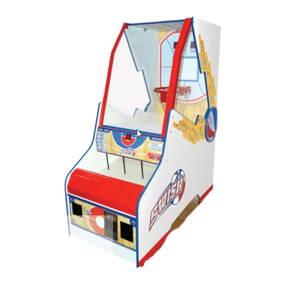
WELCOME TO: Swish Congratulations on your Swish purchase! Newly redesigned and ready to slam dunk, Swish makes a great addition to any gameroom. With cool, modern graphics and classic game play, this mini basketball free throw machine is sure to make the winning shot! Please take a moment to read through this manual and be sure to contact our factory if you have any questions, or would like some more information. -
Page 5: How To Play
HOW TO PLAY Coin up and hit the start button to release the basketballs. Shoot as many hoops as you can in the time allotted! Hurry! In the last 10 seconds, baskets are worth 3 points! Grab your tickets and play again! -
Page 6: Specifications
GAME SPECIFICATIONS WEIGHT POWER REQUIREMENTS INPUT VOLTAGE 100 to 120 220 to 240 SHIP WEIGHT 350 LBS RANGE DIMENSIONS INPUT FREQUENCY 50 HZ 60 HZ RANGE WIDTH 32” MAX START UP OPERATING DEPTH 67.25” CURRENT CURRENT HEIGHT 77.58” 1.5 AMPS @ 115 VAC 0.7 AMPS @ 115 VAC OPERATING 0.75 AMPS @ 230 VAC... -
Page 7: Dip Switch Settings
DIP SWITCH SETTINGS The dip switch bank is located on the mainboard, inside the front door of the game. *factory default settings are highlighted below SWITCH DESCRIPTION not used Jersey: Stored Coin/DBA lockout & Tickets/Credits owed not used not used... -
Page 8: Main Menu Functions
MAIN MENU FUNCTIONS 1. Press the “MENU” button and hold for 3 seconds to enter the menu 2. Scroll through the options with the “SELECT” button 3. Make your selection with the “MENU” button and scroll through each sub-menu’s options 4. - Page 9 N1- COINS/CREDITS PER PLAY Scroll through the N1 menu with the “MENU” button. Make your selection with the “SELECT” button. The factory settings are highlighted below. N2- GAME VOLUME Scroll through the N2 menu with the “MENU” button. Make your selection with the “SELECT” button. The factory settings are highlighted below.
- Page 10 N5- TICKET PATTERNS Scroll through the N5 menu with the “MENU” button. Make your selection with the “SELECT” button. The factory settings are highlighted below. POINTS TICKET 9-12 13-17 18-23 24-30 31-37 38-44 45-99 PATTERN TICKETS no tickets N6- MERCY TICKETS Scroll through the N6 menu with the “MENU”...
- Page 11 N8- FIXED TICKET PAYOUT (JERSEY) Scroll through the N8 menu with the “MENU” button. Make your selection with the “SELECT” button. The factory settings are highlighted below. This setting will make the game dispense the selected number of tickets no matter the player’s score. If not set to 0 (off), this setting overrides N5 and N6.
- Page 12 N11- GAME STATISTICS Scroll through the N15- menu with the “MENU” button. Make your selection with the “SELECT” button. The factory settings are highlighted below. The game statistics will scroll through on the display in numerical order. TOTAL GAMES PLAYED TOTAL TICKETS DISPENSED AVERAGE TICKETS PER GAME SCORING BUCKET 1...
- Page 13 N13- DIAGNOSTICS The diagnostics mode will help you troubleshoot problems and allow you to determine if all inputs are working correctly. The display will show “-” when no inputs or switches are activated. Once one or more inputs are activated, their symbols alternate on the display (see the chart below). Scoring Sensor (hoop) *Ball Gate Open *Ball Gate Closed...
- Page 14 MAINBOARD PINOUT...
-
Page 15: Mainboard Pinout Guide
MAINBOARD PINOUT GUIDE... - Page 16 MAINBOARD PINOUT GUIDE...
- Page 17 MAIN BOARD PINOUT A5NEWGEN1...
-
Page 18: Wiring Diagrams
WIRING DIAGRAMS MENU BUTTONS, COUNTERS, START SWITCH, LED’S BALL SENSOR, GATE MOTOR & SENSOR Menu Game Menu Select Counter Button Button Ticket AACE2511 Counter Ticket and Game Counters AACO1000 AACE2502 To J25 on Main Board To J22 on Main Board To J21 on Main Board To J24 on... - Page 19 WIRING DIAGRAMS COIN DOOR, DBA, TICKET DISPENSER, DISPLAY AACE2510 Bill Acceptor Cable Coin Switches Coin Door Harness (AASW9903) AACBL4A-DOOR AACE2503 Wired Normal Open To J8 on Main Board Score Display Time Display AABD4208 AABD4208 +12 V Signal AACE2506 AACE2505 AACE2506 To J5 on To J9 on Main Board...
- Page 20 WIRING DIAGRAMS POWER IN & SPEAKER Power In Cord From Wall Power Supply A5CORD5 A5PS1001 Green LED power indicator and voltage adjustment pot Line Filter A5FI9010 Power Supply Power Cable AACE2509 Outlet Strip AACE2504 Power Supply 12 Volt Cable AACE2508 To J18 “POWER IN”...
-
Page 21: Troubleshooting Guide
TROUBLESHOOTING GUIDE Troubleshooting Strategy Use common sense and a systematic method of troubleshooting to determine the exact problem, probable cause and remedy. Use the process of elimination to find the faulty component. Always check for the simple and obvious causes first such as unplugged, loose or broken wires and bad sensors, bent, pinched, stuck or jammed components. - Page 22 TROUBLESHOOTING GUIDE Problem Probable Cause Remedy Ensure game makes Check coin switches—both should be wired normally sound when coin switch is open. If one switch is “closed” the other will not work. Game not triggered. Check wiring to main board. coining up.
- Page 23 TROUBLESHOOTING GUIDE Problem Probable Cause Remedy Disconnected, loose or broken wires. Check connections and reseat J22 on main board. Meters do not Cables # AACE2500 and AACO1000 work. Replace counters. AACO1000 Faulty counters. Ticket meter will click for every notch the dispenser “sees” Game meter will click at start of next game Ticket tray is empty.
-
Page 24: Power Supply Diagnostics
POWER SUPPLY DIAGNOSTICS Diagnose Power Supply Power Supply is located under carpet inside game. Please refer to “How to Access Blower” for informa- tion. Check the small green LED light on the power supply circuit board. If the light is out there is a short somewhere. - Page 25 DOLLAR BILL ACCEPTOR DIAGNOSTICS Note: There are many different models and brands of Bill Acceptors that are used on redemption games. Your Bill Acceptor may differ from the unit shown. First determine if Bill Acceptor has power: Turn game ON—The bill acceptor should make noise as stacker cycles and green lights on outside bezel should flash.
-
Page 26: Parts List
PARTS LIST PART # DESCRIPTION A5DE2500 Backboard Decal A5DE2501 Side Seam, Left Decal A5DE2502 Side Seam, Right Decal A5DE2503 Control Panel Decal A5DE2504 Front Door Decal A5DE2505 Side Bottom Decal A5DE2506 Window Top Left Decal A5DE2507 Window Bottom Left Decal A5DE2508 Window Top Right Decal A5DE2509... -
Page 27: Parts Pictures
PARTS PICTURES AACB2501 A5TD1 A5NEWGEN1 A5PS1001 AABD4208 A5LK2000 A5LK5001 A5FI9010 AASW200 A5CORD5 A5MI2300 AAMO1001 A5PB8000 AACBL4A-DOOR AACE2500 AACE2501 AACE2502 AACE2503 AACE2504 AACE2505 AACE2506 AACE2507 AACE2508 AACE2509 AACE2510 AACE2511 AACE2512 AACE2513 AACE2514 AACO1000 AASE0020 AAPB2700 A5SP1050... - Page 28 DECAL DIAGRAM A5DE2508 Window A5DE2506 Window Decal Top Right Decal Top Left A5DE2509 Window A5DE2502 Seam A5DE2501 Seam A5DE2507 Window Decal Bottom Right Decal Right Decal Left Decal Bottom Left A5DE2505 Side A5DE2505 Side Cabinet Decal Cabinet Decal A5DE2500 Backboard Decal A5DE2503 Control Panel Decal A5DE2504...
-
Page 29: Maintenance Log
MAINTENANCE LOG If repairs are necessary, it is good practice to keep a log of repairs done and parts ordered. The chart below will assist you in tracking your game’s maintenance. DATE MAINTENANCE PERFORMED PARTS ORDERED INITIALS... -
Page 30: Technical Support
Bay Tek games. Many of our games share the same main-board electronics. This means you can buy one set of spare electronics to support many of your Bay Tek games. Spare boards allow you to get your game up and running the quickest and provide you a valuable troubleshooting option. Call our... -
Page 31: Warranty
WARRANTY Bay Tek Games warrants to the original purchaser that all game components will be free of defects in workmanship and materials for a period of 6 months from the date of purchase. If you fill out the registration card in the cashbox of the game, Bay Tek will add another 3 months to your warranty, free of charge.
Need help?
Do you have a question about the SWISH and is the answer not in the manual?
Questions and answers