Table of Contents
Advertisement
Advertisement
Table of Contents

Related Manuals for Bay Tek Games Scooby-Doo


Summary of Contents for Bay Tek Games Scooby-Doo
-
Page 2: Factory Contact Information
FACTORY CONTACT INFORMATION BAY TEK GAMES INC. Pulaski Industrial Park 1077 East. Glenbrook Drive Pulaski, WI 54162 USA JOIN OUR SERVICE FIRST NETWORK! This free service is intended to keep you up to date on the latest game information, early notification of parts specials, pertinent technical bulletins, updates on retro fit parts, software upgrades, and much more! Log on to: www.baytekgames.com/parts... -
Page 3: Table Of Contents
TABLE OF CONTENTS FACTORY CONTACT INFORMATION ....... . 2 WELCOME TO: Scooby Doo Wheel ........4 HOW TO PLAY . -
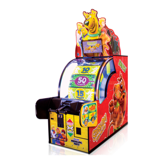
Page 4: Welcome To: Scooby Doo Wheel
WB SHEILD: TM & © WBEI. (s17) GAME INSPECTION Inspect the game for any damaged, loose, or missing parts. If damage is found, please contact your freight carrier first. Then, contact Bay Tek Games’ Service Department at 920.822.3951 or e-mail them at service@baytekgames.com for further assistance. -
Page 5: How To Play
HOW TO PLAY Lift handle up. Pull the handle down, using just the right amount of force to win big! Win the ticket value displayed on the space that stops under the arrow! -
Page 6: Specifications
GAME SPECIFICATIONS WEIGHT POWER REQUIREMENTS NET WEIGHT 485 LBS. INPUT VOLTAGE 100 to 120 220 to 240 RANGE SHIP WEIGHT 540 LBS. INPUT FREQUENCY DIMENSIONS 50 HZ 60 HZ RANGE WIDTH 32” MAX OPERATING DEPTH 77” CURRENT 78” HEIGHT (98” with marquee) 1.4 AMPS @ 115 VAC OPERATING TEMPERATURE .8 AMPS @ 230 VAC... -
Page 7: Marquee Set Up Guide
MARQUEE SET UP GUIDE Remove zip ties from cables on top of the cabinet. Route the black power cable over the right side of the cabinet. Route the VGA cable along with the 1709/1714 cable bundle over the left side of the cabinet. - Page 8 MARQUEE SET UP GUIDE CONT. Remove the 8 screws from the black plastic cover on the back of the marquee and set them aside. Carefully lift the marquee to the top of the game, being careful not to pinch any wires or cords! On the left side of the cabinet, lift the marquee up and route the VGA cable and...
- Page 9 MARQUEE SET UP GUIDE CONT. On the right side of the cabinet, lift the marquee up and route the power cable through the cut out on the bottom of the marquee. Tuck the cable into the channel so the wires don’t pinch. Pull all excess cable up and through the cut out.
- Page 10 MARQUEE SET UP GUIDE CONT. Line up the sleigh/marquee holes with the t-nuts on top of the game. Hand thread in the bolts, lock washers and washers in all four holes before securing to prevent cross threading from happening. Once all four bolts are started, use a 7/16” socket and fully tighten.
- Page 11 MARQUEE SET UP GUIDE CONT. Plug in and tighten the screws on the VGA cable to the monitor - on the bottom right hand side. Reinstall the black guard over the back of the marquee to protect the wiring. Secure the guard using the (8) black screws re- moved earlier.
-
Page 12: Standard Set Up Guide
STANDARD SET UP GUIDE Open the cashbox and get the hardware kit out for the side guards (you can dis- card the pin in the kit - this will not be needed). Attach the side guards with the bolts, flat washers, split washers and lock nuts; 4 bolts in each side, from the inside of the cabinet. -
Page 13: Main Menu Functions
MAIN MENU FUNCTIONS Press and hold the MENU button located inside the front door to access the main menu. Scroll through the options with the MENU button. Make your selections with the MENU SELECT button. -
Page 14: Reset Tickets
RESET TICKETS This option clears any owed tickets and resets to zero. *This will not reset the mechanical counters in the game RESET CREDITS This option clears any credits (games in queue) to zero. *This will not reset the mechanical counters in the game... -
Page 15: Credits Per Play
CREDITS PER GAME Factory default is highlighted below. 1 (swipe) 4 + 5, 10 & 4 + 6 plays for $5 discounts 8 + 3 plays for $5 GAME VOLUME Use the SELECT button to scroll through volume options on the slider. The red arrow shows the current setting. -
Page 16: Reset Statistics
RESET STATISTICS Clears all statistics under the “Game Statistics” to zero. *This will not reset the mechanical counters in the game PLAYER TIMEOUT OPTION Factory default is highlighted below. *MOTOR ASSIST: The game will spin the wheel if the player does not in the time allotted. *ABANDON GAME: The game ends if the player doesn’t spin the wheel in the time allotted. -
Page 17: Time And Date Menu
TIME AND DATE MENU Use this feature to set the time and date in your game. DIAGNOSTIC INFORMATION VERSION: Shows the current installed software version numbers. TOTAL CREDITS: Shows the amount of credits in queue waiting to be played. TICKETS LEFT TO DISPENSE: Shows the amount of tickets that are waiting to be dispensed. -
Page 18: Game Statistics
GAME STATISTICS TOTAL GAMES: Displays the total number of games played since the statistics were last cleared. TOTAL TICKETS: Shows the total number of tickets dispensed since the statistics were last cleared. TICKETS PER GAME: This will display the average number of tickets won per game. TOTAL MOTOR ASSISTS: Displays how many times the game had to spin the wheel for the player. -
Page 19: Ticket Patterns
TICKET PATTERN See available patterns below. 2 POINT TICKET 1000 1000 1000 1000 16.425 20.141 23.426 28.841 33.80 35.035 AVG. TICKETS/GAME AVG. TICKETS/GAME AVG. TICKETS/GAME AVG. TICKETS/GAME AVG. TICKETS/GAME AVG. TICKETS/GAME The numbers listed at the bottom of each pattern are only estimated payouts per game based on customer feedback and may vary depending on the skill of the individual player. - Page 20 TICKET PATTERNS CONT. See available patterns below. 1000 1000 59.330 73.394 3.712 3.9997 7.709 13.328 AVG. TICKETS/GAME AVG. TICKETS/GAME AVG. TICKETS/GAME AVG. TICKETS/GAME AVG. TICKETS/GAME AVG. TICKETS/GAME The numbers listed at the bottom of each pattern are only estimated payouts per game based on customer feedback and may vary depending on the skill of the individual player.
-
Page 21: Mainboard Pinout
MAINBOARD PINOUT AACE1900 SPEAKER SPEAKER DOOR OPEN LINE IN SWIT CHES POWER IN (A5CEAU010) (AACE1605) (AACE1604) (AACE1621) USED ENCODER SENSOR (AACE1608) MENU BUT TONS (AACE1613) MOT OR (AACE1616) SOLENOID CABLE SERIAL PORT TO (AACE1606) MOT HERBOARD (AACE1614) COUNT ERS 2 BOBBER 2 T ICKET (AACO1000) CHASE LIGHT S... -
Page 22: Wiring Diagrams
WIRING DIAGRAM Circuit Board Wiring LIGHT CONTROL BOARD & I/O AUX BOARD Used Used AACB6921-SD Light Control Board AACE4002 5 Volt DC Lights AACE4001 Used Used Comm from I/O Board A5CEAU010 AACE1618 Speaker Power in from AACE1605 Door Open Signal In Used Power Supply Speakers... - Page 23 WIRING DIAGRAM AC IN & POWER SUPPLY AC In & Power Supply Wiring Diagram White Wheel Marquee Directional Lights on LED lighting Illumination Side of Wheel +5 Din Grnd +5 Din Grnd AACE4000 AACE4000 AALS1701 AALS1701 AACE4003 AACE1714 AACE1620 AACE4002 5 Volt DC Lights COIN BILL AC-...
- Page 24 WIRING DIAGRAM Door Open, Speakers, Encoder Sensor, DOOR OPEN, SPEAKERS, ENCODER SENSOR, MOTOR, & SOLENOID Motor, & Solenoid Wiring Diagram AACE1703 Note: The small white jumper cables are all Speaker Speaker Back Door Switch Part # AACE1619 AACE8811 AACE8811 A5SW7000 AACE1701 AACE1702 Right Side...
- Page 25 WIRING DIAGRAM Coin Mech, Ticket Dispenser, Menu Buttons, COIN MECH, TICKET DISP., MENU BUTTONS, COUNTERS & BILL ACCEPTOR Counters & Bill Acceptor Wiring Diagram Coin Door plate To Bill Acceptor Ground Stud without mechs is Part # A5AC9091 part # A5PL1000 Blank plate for Bill Coin Door with Acceptor hole is part...
- Page 26 WIRING DIAGRAM MOTHERBOARD- MONITOR COMMUNICATION Communication Wiring Diagram AACBDI030 Monitor AACB6921-SD A5CORD20 Light Control Board AACE4001 Comm from I/O Board to A5CORD11 Light Control Board AACE1614 AAMB9A-FHD COIN BILL ACCEP- AACB1900-SD TICKET Comm from Motherboard DOOR I/O Aux Board I/O Board to Motherboard A5CEAU010 Audio Cable...
-
Page 27: Troubleshooting Guide
TROUBLESHOOTING GUIDE Troubleshooting Guide Problem Probable Cause Remedy Unplugged. Check wall outlet cable (A5CORD5) to line filter in back of game. (A5FI9010) No power to the Power strip turned off, Check rocker switch on power strip. Ensure game. or plugs unplugged. power cords are pushed up into power strip securely. - Page 28 TROUBLESHOOTING GUIDE Troubleshooting Guide Problem Probable Cause Remedy Volume too low. Increase the volume by pressing Menu button, scroll to volume slider bar and adjust. Check audio cable connections from motherboard to I/O board to speakers Audio Loose wire. (A5CEAU010, AACB1900-SD, AACE1605, AACE8811) AACE8811 SPEAKER BILL...
- Page 29 Troubleshooting Guide TROUBLESHOOTING GUIDE Problem Probable Cause Remedy I/O Serial cable unplugged from I/O board to None of inputs work. No coin Game turns motherboard. Inspect cable AACE1614. Replace if up, no test buttons, display on, but some needed. of the may say door open.
- Page 30 TROUBLESHOOTING GUIDE Troubleshooting Guide Problem Probable Cause Remedy Weak encoder sensor. Replace sensor. Game says you won tickets even (AACB1901) though wheel is still spinning. Attract mode spinning wheel should slow down Game gives tickets as soon as money is inserted during attract mode. enough so it will not trigger win.
- Page 31 Troubleshooting Guide TROUBLESHOOTING GUIDE Problem Probable Cause Remedy Verify game is registering a Display monitor will show ticket value won. If Tickets not dispensing not – see “Wheel Sensor troubleshooting.” win. from either ticket dispenser. Game will not dispense with any door open. Ensure “Door Open”...
- Page 32 TROUBLESHOOTING GUIDE Troubleshooting Guide Problem Probable Cause Remedy Enter menu, ensure this is not Change to “Motor Assist” set to “Abandon Game”. Motor will not Enter menu, check diagnostic assist the slow Change “abandon game” to “Motor Assist”. information for "motor watchdog Turn game off, and then back on to clear error.
- Page 33 TROUBLESHOOTING GUIDE Troubleshooting Guide Problem Probable Cause Remedy Spin meter never Encoder sensor dirty or faulty. Clean sensor and replace if needed. (AACB1901) increases. Pinched, broken, or Inspect wiring and replace cable if needed. (AACE1705) disconnected wiring. Encoder sensor not seeing wheel spin.
-
Page 34: Door Open Error
TROUBLESHOOTING GUIDE Troubleshooting Guide Problem Probable Cause Remedy Swap connectors at the 2 buttons Replace button if problem stays with button.(AAPB2700) Menu Pinched, broken, or Inspect crimp to ensure good connection. Check Buttons do not disconnected wiring connections from menu buttons to main board. Check continuity on AAPB2700, AACE1613 work. -
Page 35: Limit Switch Map
DOOR OPEN ERROR *THIS IS A SAFETY MATTER AND THE LIMIT SWITCHES MUST NOT BE DISABLED OR INJURY MAY OCCUR! THERE ARE 5 LIMIT SWITCHES: 1 ON THE BACKDOOR, 1 IN THE LEFT SIDE DOOR, 1 IN THE RIGHT SIDE DOOR, 1 IN THE LEFT FRONT DOOR AND 1 IN THE RIGHT FRONT DOOR. - Page 36 LIMIT SWITCH MAP DOOR LIMIT SWITCHES ARE THE PULL/PUSH TYPE. THE SWITCH CAN BE PULLED OUT SO THE GAME THINKS THE DOOR IS CLOSED AND WILL FUNCTION NORMALLY. WE DON’T RECOMMEND DOING THIS UNLESS IT’S NECESSARY FOR REPAIR OR MAINTENANCE. FRONT AACE1604 FRONT...
-
Page 37: How To Update Software
HOW TO UPDATE SOFTWARE How to Update Software The software is programmed onto a USB thumb drive dongle . It pushes into any of the USB sockets on the motherboard. To Change Software: Power game Off. Remove USB stick AAMB9A-FHD Insert new USB Motherboard Power game On. -
Page 38: Adjusting Encoder Wheel Sensor
ADJUSTING ENCODER WHEEL SENSOR Adjusting Wheel Sensor The arrow pointer will show the customer which ticket value they have won. Remember: There is a ½ inch buffer zone between panels that provide a small margin of error. This space is also present on the big bonus values. It allows a big bonus value to score even though the pointer may be slightly above or below the actual sticker on the wheel. -
Page 39: Brake Adjustment
If it does - tighten brake. If the wheel rocks backward during a game, it will score wrong if it rocks over a notch. CARD SWIPE INSTALL INSTRUCTIONS Card Swipe System Instructions Coin Switches and Lights In the menu: Set “Credits Per Game” to 1(swipe) Black wire is ground. - Page 40 ADJUSTING THE BRAKE 1. IF THE BRAKE NEEDS ADJUSTING, OPEN THE LEFT SIDE DOOR. 2. YOU WILL SEE A SPRING LOADED BOLT COMING UP FROM THE BRAKE. 3. PULL THE BOLT UP AND SPIN THE LOCK NUT TO ADJUST. YOU ONLY NEED TO DO 2 REVOLUTIONS TO ALTER THE PRESSURE.
-
Page 41: Puppy Video Wizard Error
PUPPY VIDEO WIZARD ERROR If the monitor has been changed or game loses monitor settings, this screen will come up upon power up. The settings will have to be resaved. 1. Plug a PS/2 keyboard into the key- board port of the motherboard. (purple colored port) 2. -
Page 42: Removing The Handle
REMOVING THE HANDLE THE HANDLE IS DESIGNED TO BE REMOVED FROM THE GAME. THIS WILL ALLOW A TECHNICIAN TO WORK ON THE SOLENOID ASSEMBLY WITH A REDUCED CHANCE OF ACCIDENTAL INJURY. TOOLS NEEDED: - 1/2 INCH SOCKET - 1/2 INCH WRENCH THERE IS A BOLT, LOCK WASHER AND LOCK NUT UNDER THE SPEAKER BRACK-... -
Page 43: Cleaning The Window
CLEANING THE WINDOW 1. OPEN THE FRONT DOORS AND UNLOCK THE 2 CLAPS HOLDING THE FRONT WINDOWN IN, FIG. 1. 2. THE FRONT WINDOW WILL NOW SLIDE UP LIKE A ROLL TOP DESK. FIG. 2. 3. REMOVE THE BACK DOOR, THE TOP OF THE FRONT WINDOW CAN NOW BE REACHED. - Page 44 POWER SUPPLY DIAGNOSTICS STEP 3 1. CHECK THE POWER CABLE TO THE GAME. 2. CHECK THE CONNECTIONS STEP 4 ON THE POWER SOCKET ON THE LOWER BACKDOOR OF THE GAME, FIG. 1. STEP 5 3. CHECK CONNECTION TO THE POWER SUPPLY, FIG. 2. 4.
-
Page 45: Diagnostics
BILL ACCEPTOR DIAGNOSTICS Bill Acceptor Diagnostics Note: There are many different models and brands of Bill Acceptors that are used on redemption games. Your Bill Acceptor may differ from the unit shown. Standard DBA is MEI # AE2451-U5E Part # A5AC9091 Determine if Bill Acceptor has power: Turn game ON—The bill acceptor should make noise as stacker cycles and green lights on outside bezel should flash. -
Page 46: Arm Bracket Maintenance
ARM BRACKET MAINTENANCE IT IS IMPORTANT TO CHECK THE BOLTS HOLDING THE ARM BRACKET TO THE GAME CABINET PERIODICALLY TO ENSURE THEY STAY TIGHT. FAILURE TO DO SO MAY CAUSE INJURY OR DAMAGE TO YOUR GAME. FACTORY RECOMMENDATIONS SUGGEST YOU CHECK THESE BOLTS MONTHLY DEPENDING ON THE USAGE OF THE GAME. -
Page 47: Pivot Assembly Diagram
A5NULO050 AASO4150 Pivot Assembly A5ME4154 Scooby Doo A5PICZ001 Exploded View Diagram A5BOPH301 A5BOHH115 A5BURU040 A5NULO080 A5BURU050 A5BOPH301 A5WASI010 A5ME4172 A5NUHX060 A5ME4161 A5RICZ010 A5ME4224 A5ME4172 A5ME4156 A5ME4174 A5ME4171 A5RICZ010 A5ME4178 A5PICZ001 A5SLZN010 A5ME4157 If you have any questions or need further assistance please contact Baytek Games at 920-822-3951 Ext 1102... -
Page 48: Parts Lists
Parts List PARTS LIST PART # DESCRIPTION PART # DESCRIPTION A5BK9999 A5ME4164 Bracket, Power Supply Mounting Metal,Clutch Pivot Plate A5BKSW001 A5ME4165 Bracket,Switch,One Bend Metal,Clutch Swivel Plate A5BKSW002 A5ME4170 Bracket,Switch,Two Bend Metal, Wheel Motor Bracket A5BURU040 A5ME4171 Bumper,1-1/2" Dia X 3/4"H Metal,T-Handle A5BURU050 A5ME4172... - Page 49 PARTS LIST Parts List PART # DESCRIPTION PART # DESCRIPTION AASO4150 A5CA1005 Solenoid Assy,Spinning Wheel Caster,250# Load,Swivel/Lock A5BBW-KIT A5CL1004 Cable Kit, 1614/1620 Clamp,Versa Latch A5BBW-KIT1 A5ME4169 Cable Kit, 1605/1613 Metal,Front Guard AACBL4A-DOORA A5ME4183 Metal, Right Front Door Cable, Double Coin Door A5ME4184 A5CEAU010 Metal,Left Front Door...
- Page 50 PARTS PICTURES Parts Pictures A5BK9999 A5BKSW001 A5BURU040 A5BURU050 A5CB8020 AACBDI030 A5CH1007 A5CORD12 A5CORD11 A5CORD 5 A5EB9000 A5EX1007 A5FI9010 A5GE4202 A5GE4203 A5LK2001 A5LK5002 A5ME4152 A5ME4153 A5ME4156 A5ME4157 A5ME4159 A5ME4161 A5ME4170 A5ME4171 A5ME4172 A5ME4174 A5ME4177 A5ME4178 A5ME4179 A5ME4180 A5ME4181 A5ME4182 A5ME4202 A5ME4205 AAMO4101 A5SP9107...
- Page 51 PARTS PICTURES Parts Pictures A5ME4224 A5SP1003 A5PL9097 A5SW7000 A5OU1000 A5SREX050 AASW200 A5SWIFFER A5TD1 A5TT4100 A5TT4101 A5VF4153 AACO1000 AASO4150 A5CEAU010 AACE1610 AACE1611 AACE1612 AACE1618 AACE1619 AACE1625 AACE1704 AACE1705 AACE1708 AACE1714 AACE1716 AACE8811 AAJP9092 AAPB2700 AALS1701 AACB1901 A5CA1005 W5TM4000 A5ME4183 A5ME4169 A5ME4184 AACB1900-SD AAMB9A-FHD...
-
Page 52: Maintenance Log
MAINTENANCE LOG If repairs are necessary, it is good practice to keep a log of repairs done and parts ordered. The chart below will assist you in tracking your game’s maintenance. DATE MAINTENANCE PERFORMED PARTS ORDERED INITIALS... -
Page 53: Technical Support
Bay Tek games. Many of our games share the same main-board electronics. This means you can buy one set of spare electronics to support many of your Bay Tek games. Spare boards allow you to get your game up and running the quickest and provide you a valuable troubleshooting option. Call our... -
Page 54: Warranty
WARRANTY Bay Tek Games warrants to the original purchaser that all game components will be free of defects in workmanship and materials for a period of 6 months from the date of purchase. If you fill out the registration card in the cashbox of the game, Bay Tek will add another 3 months to your warranty, free of charge.
Need help?
Do you have a question about the Scooby-Doo and is the answer not in the manual?
Questions and answers