Table of Contents
Advertisement
Advertisement
Table of Contents

Related Manuals for Bay Tek Games Willy Crash


Summary of Contents for Bay Tek Games Willy Crash
-
Page 2: Factory Contact Information
FACTORY CONTACT INFORMATION BAY TEK GAMES INC. Pulaski Industrial Park 1077 East. Glenbrook Drive Pulaski, WI 54162 USA JOIN OUR SERVICE FIRST NETWORK! This free service is intended to keep you up to date on the latest game information, early notification of parts specials, pertinent technical bulletins, updates on retro fit parts, software upgrades, and much more. -
Page 3: Table Of Contents
WELCOME TO: Willy Crash ........ -
Page 4: Welcome To: Willy Crash
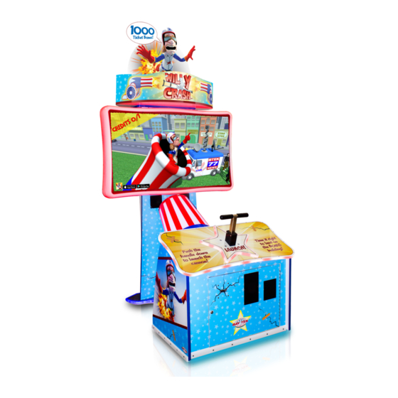
WELCOME TO: Willy Crash Congratulations on your purchase! Detonate the TNT plunger to launch Willy Crash into a 3D cityscape, aiming for the tops of buildings to score big! Miss and he will hilariously crash into a number of cringe- worthy, interactive obstacles. -
Page 5: How To Play
HOW TO PLAY Time your launch to shoot Willy into the air, aiming to land on a building. Press plunger down to launch Willy from the cannon! Collect tickets! -
Page 6: Specifications
GAME SPECIFICATIONS WEIGHT POWER REQUIREMENTS NET WEIGHT 400 LBS. INPUT VOLTAGE 100 to 120 220 to 240 RANGE SHIP WEIGHT 450 LBS. INPUT FREQUENCY DIMENSIONS 50 HZ 60 HZ RANGE WIDTH 53” MAX OPERATING DEPTH 57” CURRENT HEIGHT 107” 3.1A at 100-120VAC OPERATING TEMPERATURE 1.9A at 220-240VAC FAHRENHEIT... -
Page 7: Dip Switch Settings
DIP SWITCH SETTINGS The dip switch bank is located on the mainboard, inside the front door of the game. *factory default settings are highlighted below *UP IS ON* SWITCH DESCRIPTION Show Game DOES NOT DISPENSE TICKETS AND CLEARS ALL ACCUMULATED CREDITS Amusement Only DOES NOT DISPENSE TICKETS NJ Lockout... -
Page 8: Setup Guide
SETUP Take keys off of control panel. Use key H95 to open front cabinet door. *Key E100 is for the cashbox* Take out the power cord and hardware kit. Take keys off back panel of game with the key used for front cabinet. Set back cabinet door aside... - Page 9 SETUP Plug in power cord to the box in the bottom right corner of the game. Make sure it goes through the hole at the bottom of the game. Replace back door. Take marquee piece and peel off plastic film. Then take a ladder to get up to marquee.
-
Page 10: Adjustable Marquee
ADJUSTABLE MARQUEE Remove Willy to reach a game height of 7’ 2”... -
Page 11: Main Menu Functions
MAIN MENU FUNCTIONS Factory defaults are highlighted below. MAIN MENU OPTIONS CLEAR CREDITS/ Press the MENU SELECT button 3 times to clear tickets and credits owed TICKETS RESET FACTORY Press MENU SELECT button 3 times to reset all settings to factory defaults DEFAULTS MUTE... -
Page 12: Volume And Attract
VOLUME AND ATTRACT Factory defaults are highlighted below. VOLUME & ATTRACT OPTIONS ATTRACT VOLUME GAME VOLUME JACKPOT VOLUME ATTRACT TIMING (MINUTES) (OFF) -
Page 13: Game Settings
GAME SETTINGS Factory defaults are highlighted below. GAME SETTINGS GAME MODE TICKETS POINTS REPEAT DISABLE REWARD CANNON SPEED AUTO EASY NORMAL HARD AUTO ADJUSTS THE BONUS BUILDING MOVE AFTER WIN VERY BUILDING LOCATION ON EASY NORMAL HARD adjust the building to the next HARD THE NUMBER (DETERMINES... -
Page 14: Payout Settings
PAYOUT Factory defaults are highlighted below. PAYOUT SETTINGS CREDITS DEFAULT: 1 (INC OF CARD READER ENABLED DISABLE BONUS BUILDING 1000 1500 2000 2500 LARGE BUILDING DEFAULT: 100 (INC OF MEDIUM BUILDING DEFAULT: 35 (INC OF SMALL BUILDING DEFAULT: 25 (INC OF ALLEY VALUE DEFAULT: 5 (INC OF... -
Page 15: Statistics
STATISTICS DIAGNOSTICS... -
Page 16: Ticket Patterns
TICKET PATTERNS *DEFAULT PATTERN HIGHLIGHTED IN ORANGE* PATTERN PATTERN PATTERN PATTERN PATTERN PATTERN BONUS 1000 1500 TALL MEDIUM SMALL ALLEY COST PER PLAY 1.50 0.75 0.50 0.25 AVG TIX PER PLAY 30-40 50-60... -
Page 17: Circuit Board Pinouts
CIRCUIT BOARD LAYOUT CIRCUIT BOARD LAYOUT AACE8016 AACE8002 Power to Plunger Sensor 8001 Board AACE8028 Right LED’s A5CORD58 CE8015 CE8017 CE8015 USB Commu- AACB8001 AACE8009 nication from Light Board Floor Motherboard CE8000 CE8014 CE8006 LED’s AACB5156 Power Dist. Board AACE8016 AACE8008 Monitor Power In... - Page 18 WIRING DIAGRAM WIRING DIAGRAM COIN MECH, MENU AND COUNTER COIN MECH, MENU, AND COUNTER Coin Switches and Lights AACE8004 To Game AACBL4A-DOOR Ground Bill Acceptor AACE8006 A5AC9091 UCL Connector Card Swipe system cable would be plugged into this connector. AACE8006 AACE8006 AACE8004 Power In...
- Page 19 WIRING DIAGRAM WIRING DIAGRAM SPEAKERS AND MOTHERBOARD COMMUNICATION SPEAKERS AND MOTHERBOARD COMMUNICATION Speaker Speaker AACE8811 AACE8811 3.3 Ohms 3.3 Ohms 55” TV A5MO5502 A5CORD36 HDMI Cable to Monitor AACE8001 AACE8001 A5CB8000 Graphics AAMB10-HD Card AACB8001 Light Board A5CORD58 USB Communication from Motherboard A5CORD58 USB Communication...
-
Page 20: Wiring Diagrams
WIRING DIAGRAM WIRING DIAGRAM SENSORS AND LEDS SENSORS AND LEDS The LED on the sensor is normally off. It comes On when blocked to launch cannon. AACB3850A Plunger Sensor AACE8002 AACE8010 Right Side AACE8028 Floor Lights Red & Yellow LED AACE8010 is ON when board is A5CORD58... - Page 21 WIRING DIAGRAM WIRING DIAGRAM AC IN AND POWER SUPPLY AC IN AND POWER SUPPLY AACE8025 60 Watt 60 Watt Inside cabinet Work LED AC Bulb AC Bulb A5LI0003 A5LI0003 AACB8001 Light Board AACB9604 I/O Aux Board AACE8868 AACE8868 AACE8018 AACE8014 AACE8017 A5CB9600 12 VDC to...
- Page 22 TROUBLESHOOTING TROUBLE SHOOTING GUIDE Troubleshooting Strategy Use common sense and a systematic method of troubleshooting to determine the exact problem, probable cause and remedy. Use the process of elimination to find the faulty component. Always check for the simple and obvious causes first such as unplugged, loose or broken wires and bad sensors, bent, pinched, stuck or jammed components.
- Page 23 TROUBLESHOOTING TROUBLE SHOOTING GUIDE Problem Probable Cause Remedy Game not coining up. Check for I/O board USB Refer to “I/O Aux Board Issue” diagnostic cable communication. Section. Ensure game makes sound Check coin switches—both should be wired when coin switch is triggered. normally open.
-
Page 24: Troubleshooting Guide
TROUBLESHOOTING Troubleshooting Guide Problem Probable Cause Remedy LED’s to light up playfield Check for proper connection from power supply to Power receive 12 Volts DC from Distribution Board and then to LED strips. Inside LED power supply through the Check continuity. (AACE8025, AACE8017, AACB5156, cabinet lighting Power Distribution Board. - Page 25 TROUBLESHOOTING TROUBLE SHOOTING GUIDE Problem Probable Cause Remedy Opto Sensor on ticket Blow dust from sensor and clean with Tickets do dispenser dirty. isopropyl alcohol. not dispense Faulty ticket dispenser. Replace with working dispenser to isolate the or Wrong Tickets on problem.
- Page 26 TROUBLESHOOTING TROUBLE SHOOTING GUIDE Problem Probable Cause Remedy Monitor HDMI cable unplugged from video card. Monitor shows “No The game will not boot up with the monitor disconnected Signal” Monitor not working. Faulty or loose RAM on motherboard Large power connector unplugged on motherboard AAMB10-HD Power down, Small power connector unplugged on motherboard...
-
Page 27: Diagnostics
DIAGNOSTICS POWER SUPPLY POWER SUPPLY DIAGNOSTICS 1.) Verify AC power to game. Check power strip in front door. The rocker switch should be illuminated. 2.) Check connection to power supply. 3.) Ensure Power Supply switch is set to 115V (or 230V) (Some model power supplies may not have this) 4.) Ensure Power switch is on. - Page 28 DIAGNOSTICS BILL ACCEPTOR BILL ACCEPTOR DIAGNOSTICS Note: There are many different models and brands of Bill Acceptors that are used on redemption games. Your Bill Acceptor may differ from the unit shown. Standard DBA is MEI # AE2451-U5E Part # A5AC9091 Determine if Bill Acceptor has power: Turn game ON—The bill acceptor should make noise as stacker cycles and green lights on outside bezel should flash.
-
Page 29: Things You Don't Know About Willy Crash
2 THINGS YOU DO NOT KNOW ABOUT WILLY CRASH 6 THINGS YOU DO NOT KNOW ABOUT WILLY CRASH A5PS1013 A5TD1 A5CB9600 AACB5156 AACB3850A AAMB10-HD 1.) Willy is modeled after a real life person - Carl T. No, he has never been shot out of a cannon. -
Page 30: Handle Assembly Exploded View
HANDLE ASSY EXPLODED VIEW HANDLE ASSY EXPLODED VIEW A5CO4400 AAME4415 Screws are A5SCSQ001 WARR9824 (8 per assembly) A5ME4414-BLK A5BOCG090 A5BOPH220 A5WAFL030 A5NUNY050 A5NULO050 A5BRZN010 A5NUNY050 A5HKSY020 WARR9824 A5SP1801 WACA8003 A5WAFL050 WACA8003 A5SCHX016 A5WAFL050 A5NUNY070 A5RICZ010 A5SENY071 A5SENY170 A5PICV030... -
Page 31: Parts List
PARTS LIST PARTS LIST PART # DESCRIPTION PART # DESCRIPTION A5BK1013 Bracket, Pushbutton/Counters A5CORD1 Cord,Power,10' Works W/Outlet Strip A5BK6035 Bracket, Light A5CORD36 Cord, 8' HDMI To HDMI A5BK9999 Bracket, Power Supply Mounting A5CORD5 Cord, AC Computer Cord, 6.5' A5BTRT010 #4 Nylon Push Pins A5CORD58 Cable, USB, Male A To Micro, 3ft A5BURU075... -
Page 32: Parts Pictures
PARTS PICTURES PARTS PICTURES A5BK1013 A5BK6035 A5BK9999 A5BURU075 A5CB1499 A5CO4203 A5CO4400 A5FI9010 A5HO1003 A5LI0003 A5LK2001 A5LK5002 A5ME2035 A5ME4182 A5ME4414-BLK AAME4415 A5ME5508 A5PL4200 A5PL8900 A5RICZ010 AASW200 A5DE0042 A5DE8010 A5DE8011 A5DE8012 A5DE8013 A5DE8014 A5DE8015 A5DE8016 A5DE8017 A5DE8018 A5DE8019 A5DE8020 A5DE8021 A5DE8022 W5HG1025 W5HG1065 W5KE5000 W5TM4002 AACO1020... - Page 33 PARTS PICTURES PARTS PICTURES A5PS1013 A5TD1 A5CB9600 AACB5156 AACB3850A AAMB10-HD BLANKING PLATES AVAILABLE A5PL4200 DBA Plate instead of Upstacker Bill Acceptor A5PL9998 Plate used instead of Coin Mechanisms A5PL8900 Plate used for Bill Validator A5PL9995 Plate used instead of ticket dispenser...
-
Page 34: Decal Diagram
DECAL DIAGRAM A5DE8023 (installed by customer) A5DE8010 Marquee Back A5DE8014 Marquee Front A5DE8015 Monitor Cover A5DE8016 Control Panel A5DE8011 Cannon Wrap A5DE8017 Star A5DE8020 Pillar A5DE8012 Floor Right (A5DE8013 Floor Left other side) A5DE8018 Outter Door A5DE8022 Side Panel Right A5DE8019 Inner Door (A5DE8021 Side Panel Left other side) -
Page 35: Maintenance Log
MAINTENANCE LOG If repairs are necessary, it is good practice to keep a log of repairs done and parts ordered. The chart below will assist you in tracking your game’s maintenance. DATE MAINTENANCE PERFORMED PARTS ORDERED INITIALS... -
Page 36: Tech Support
Bay Tek games. Many of our games share the same main-board electronics. This means you can buy one set of spare electronics to support many of your Bay Tek games. Spare boards allow you to get your game up and running the quickest and provide you a valuable troubleshooting option. Call our... -
Page 37: Warranty
WARRANTY Bay Tek Games warrants to the original purchaser that all game components will be free of defects in workmanship and materials for a period of 6 months from the date of purchase. If you fill out the registration card in the cashbox of the game, Bay Tek will add another 3 months to your warranty, free of charge.
Need help?
Do you have a question about the Willy Crash and is the answer not in the manual?
Questions and answers