Table of Contents
Advertisement
Advertisement
Table of Contents

Subscribe to Our Youtube Channel
Related Manuals for Bay Tek Games Connect 4


Summary of Contents for Bay Tek Games Connect 4
-
Page 2: Factory Contact Information
FACTORY CONTACT INFORMATION BAY TEK GAMES INC. Pulaski Industrial Park 1077 East. Glenbrook Drive Pulaski, WI 54162 USA JOIN OUR SERVICE FIRST NETWORK! Scan here! This free service is intended to keep you up to date on the latest game information, early notification of parts specials, pertinent technical bulletins, updates on retro fit parts, software upgrades, and much more. -
Page 3: Table Of Contents
WELCOME TO: CONNECT 4 ........4... -
Page 4: Welcome To: Connect 4
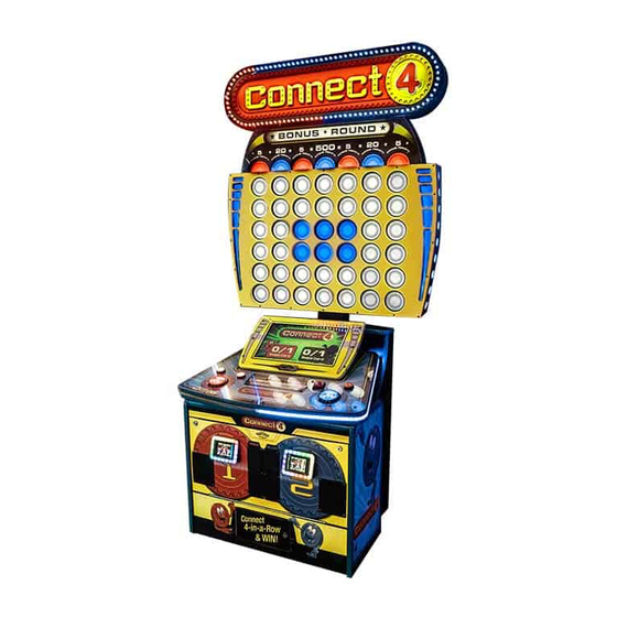
WELCOME TO: CONNECT 4! Congratulations on your Connect 4 purchase! Everyone young and old loves the nostalgic gameplay of Connect 4 , and Bay Tek has brought the spirit of family fun to your game room with this larger-than-life version of Hasbro’s classic game of vertical checkers. -
Page 5: Specifications
GAME SPECIFICATIONS POWER REQUIREMENTS WEIGHT INPUT VOLTAGE 100 to 120 220 to 240 325 lbs. NET WEIGHT RANGE 380 lbs. SHIP WEIGHT INPUT FREQUENCY 50 HZ 60 HZ RANGE DIMENSIONS MAX START UP OPERATING WIDTH 44” CURRENT CURRENT 3 AMPS @ 115 VAC 2 AMPS @ 115 VAC DEPTH 34”... -
Page 6: How To Play
HOW TO PLAY Pick a color and insert credits to play against the game or a friend. Move your chip left and right at the top of the grid with the arrow buttons, and hit the big button to drop your chip before the time runs out! Be the first to align 4 of your chips hori- zontally, vertically, or diagonally to win and... -
Page 7: Quick Set Up
QUICK SET UP (marquee installation) Remove the back panel of the playfield (8 screws) and set aside. Lift the marquee into place and drop the cables down through the hole in the top of the playfield. Align the marquee with the back edge of the playfield and secure the brackets with included black wood screws. - Page 8 QUICK SET UP Place the game near its final location. Plug the power cord into a standard 110V electrical outlet. Wait for the game to boot up, then adjust settings accordingly if desired.
-
Page 9: Dip Switch Settings
DIP SWITCH SETTINGS The dip switch bank is located on the mainboard, inside the center of the player console. *factory default settings are highlighted below SWITCH DESCRIPTION unused unused Jersey Shore (credit lockout/tickets owed) unused... -
Page 10: Main Menu
MAIN MENU FUNCTIONS Press the MENU BUTTON, located inside the cabinet below the red player station, to enter the Main Menu. Scroll through the menu with the MENU BUTTON, and make your selections with the MENU SELECT* button. * to clear credits, press the Menu Select button while not in the menu. -
Page 11: Game Setup Menu
GAME SETUP MENU FACTORY DEFAULTS ARE HIGHLIGHTED IN YELLOW BELOW Coins/Credits Number of credits per per Game game, per player (card swipe) Seconds allowed per Time Per Turn chip drop before auto- drop 5/1/1 10/5/5 20/5/10 30/10/15 40/10/20 50/10/20 50/20/25 Tickets 6-10 avg 10-14 avg... -
Page 12: Game Setup- Washington State
GAME SETUP MENU- WASHINGTON STATE FACTORY DEFAULTS ARE HIGHLIGHTED IN YELLOW Coins/Credits Number of credits per per Game game, per player (card swipe) Seconds allowed per *Time Per Turn chip drop before auto- drop 5/1/1 10/5/5 20/5/10 30/10/15 40/10/20 50/10/20 50/20/25 6-10 avg 10-14 avg... -
Page 13: Statistics Menu
STATISTICS MENU Total Games Displays how many games have been played Average Time per Game Displays how long the average game lasts Total Red Games Displays how many games were played on the red side Total Blue Games Displays how many games were played on the blue side Total Tickets Displays how many tickets the game has given out Average Tickets per Game... -
Page 14: Diagnostics Menu
DIAGNOSTIC MENU Selecting this diagnostic will light up the playfield in solid red, blue, and Change Playfield Color white to test for dim or burned out LED circuit boards Selecting this diagnosic will turn the bonus value lights on and off to test Toggle Bonus Lights for dim or burned out LED circuit boards Left Arrow Red... -
Page 15: Motherboard Pintout
MOTHERBOARD PINOUT ... - Page 16 MOTHERBOARD PINOUT...
- Page 17 MOTHERBOARD PINOUT...
-
Page 18: How To: Replace Player Button Switches
HOW TO: Replace Player Button Switches Player Station Pushbuttons can be accessed from the player station front door— reaching up underneath the player station. The switches must be removed first before button can be removed and /or replaced. Important: The switches do not pull straight off! They must be given a slight twist, then removed—as follows: Left and Right Buttons: Center Drop Button:... -
Page 19: How To: Update Software
HOW TO: Update Software Needed for Software Updated: 1 USB stick with motherboard software 1 USB stick with minigen software 1- Minigen Software Load: Game must be powered on for this procedure. Open the front door of the cabinet and locate the minigen board. -
Page 20: Diagnostics: Main Board Power Supply
DIAGNOSTICS: Motherboard Power Supply Monitor not coming on? 1.) Verify AC power to front of game. Check power strip in bottom front of game for light ON inside rocker switch. If light is not ON, remove back panel of cabinet and check AC power in and Power Strip in that location. -
Page 21: Diagnostics: Dollar Bill Acceptor
DIAGNOSTICS: Dollar Bill Acceptor Note: There are many different models and brands of Bill Acceptors that are used on redemption games. Your Bill Acceptor may differ from the unit shown. First determine if Bill Acceptor has power: Turn game ON—The bill acceptor should make noise as stacker cycles and green lights on outside bezel should flash. -
Page 22: Troubleshooting Guide
TROUBLESHOOTING GUIDE Troubleshooting Strategy Use common sense and a systematic method of troubleshooting to determine the exact problem, probable cause and remedy. Use the process of elimination to find the faulty component. Always check for the simple and obvious causes first such as unplugged, loose or broken wires and bad sensors, bent, pinched, stuck or jammed components. - Page 23 TROUBLESHOOTING GUIDE Symptom Probable Cause Remedy Fill ticket tray. Replace low ticket switch(AASW200). Ticket tray empty due to faulty low ticket switch or broken/ Repair wiring. Clean ticket tray of dirt, loose tickets or Tickets do not loose wires. Switch stuck or debris.
- Page 24 TROUBLESHOOTING GUIDE Symptom Probable Cause Remedy Ensure bill acceptor has 110 Acceptor should cycle stacker at game power up. If not, check cable connections Volts AC. Dollar Bill Acceptor to power strip. not functioning. Clean with bill reader cleaning card(A5CC9000) Dirt or debris in acceptor slot.
- Page 25 TROUBLESHOOTING GUIDE Symptom Probable Cause Remedy Monitor will have to be removed from game, and ad- justed from front of screen. Monitor prob- Blurry Monitor Too bright, or lems Refer to “How to Remove Monitor” Section dim. Use menu buttons to access monitor adjustment Communication between Refer to Motherboard to MiniGen Board Both sides do...
- Page 26 TROUBLESHOOTING GUIDE Symptom Probable Cause Remedy Bonus Feature not enabled in Enter menu and set “Bonus Type” to “One Hit Bonus” Bonus menu. Lights do Check wiring continuity from light boards to main Board. Faulty cable from bonus light not come (AACE4625, AACE4607, AACE4600) Check for pinched, boards in top back of game to on at end...
- Page 27 TROUBLESHOOTING GUIDE Symptom Probable Cause Remedy Remove plastic cover and examine LED strip. Lights under player LED strip under stations do not light up. faulty Check cables from LED strips to main board. (AACE4620, AACE4621, AACE4608) Faulty Cable Replace main board. (AANEWGEN-PJ) Faulty Main Board Surface mounted Replace main board.
-
Page 28: Maintenance Log
MAINTENANCE LOG If repairs are necessary, it is good practice to keep a log of repairs done and parts ordered. The chart below will assist you in tracking your game’s maintenance. DATE MAINTENANCE PERFORMED PARTS ORDERED INITIALS... -
Page 29: Technical Support
Bay Tek games. Many of our games share the same main-board electronics. This means you can buy one set of spare electronics to support many of your Bay Tek games. Spare boards allow you to get your game up and running the quickest and provide you a valuable troubleshooting option. Call our... -
Page 30: Warranty
WARRANTY Bay Tek Games warrants to the original purchaser that all game components will be free of defects in workmanship and materials for a period of 6 months from the date of purchase. If you fill out the registration card in the cashbox of the game, Bay Tek will add another 3 months to your warranty, free of charge. -
Page 31: Replacement Ticket Patterns
REPLACING TICKET PATTERNS Locate the ticket pattern cover up decal and clear acrylic faceplate in the cashbox. Select and cut out your desired pattern from the following pages. This must match the set- tings selected in the Game Setup Menu. Tape the cut out ticket values to the back of the cover up decal, making sure the numbers line up with the holes.
Need help?
Do you have a question about the Connect 4 and is the answer not in the manual?
Questions and answers