Table of Contents
Advertisement
Advertisement
Table of Contents

Related Manuals for Bay Tek Games Crank It Revolution


Summary of Contents for Bay Tek Games Crank It Revolution
-
Page 2: Factory Contact Information
FACTORY CONTACT INFORMATION BAY TEK GAMES INC. Pulaski Industrial Park 1077 East Glenbrook Drive Our Vision: Pulaski, WI 54162 U.S.A. We aspire to be the www.baytekgames.com best in the world at developing and man- ufacturing coin oper- ated games for our JOIN SERVICE FIRST NETWORK! customers. -
Page 3: Table Of Contents
TABLE OF CONTENTS FACTORY CONTACT INFORMATION WELCOME TO: CRANK IT REVOLUTION! HOW TO PLAY SPECIFICATIONS SAFETY PRECAUTIONS DIP SWITCH SETTINGS MAIN MENU FUNCTIONS CREDITS PER PLAY TICKET PATTERNS 9-11 GAME VOLUME ATTRACT MODE VOLUME PRINTER SETTINGS WHEEL POSITION DIAGNOSTCS TICKET VALUE DIAGNOSTICS... -
Page 4: Welcome To: Crank It Revolution
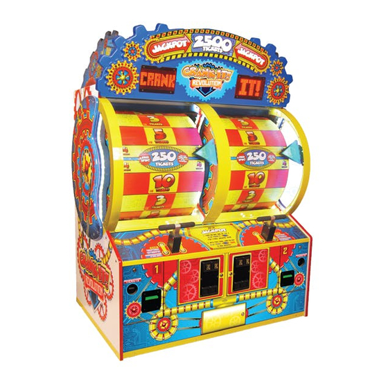
WELCOME TO: CRANK IT REVOLUTION! Congratulations on your Crank It Revolution purchase! Double the excitement of the original Crank It, Crank It Revolution offers two players at a time to spin and win a big bonus! With fun, colorful graphics, attractive LED lighting, dot-matrix display, and a goofy, infectious... -
Page 5: How To Play
HOW TO PLAY Crank it up… Crank it down… Watch the wheel spin ‘round and ‘round! Land the arrow on a space… Put a smile on your face! Land on a blue space twice in a row… And off with jackpot tickets you go! -
Page 6: Specifications
SPECIFICATIONS WEIGHT POWER REQUIREMENTS WEIGHT 800 lbs. INPUT VOLTAGE RANGE 100 to 120 VAC or 220 to 240 VAC SHIP WEIGHT 900 lbs. DIMENSIONS INPUT FREQUENCY RANGE 50 HZ 60 HZ WIDTH 57.5 DEPTH 39” MAX START UP OPERATING CURRENT HEIGHT 83”... -
Page 7: Dip Switch Settings
DIP SWITCH SETTINGS The dip switch bank is located on the main board, inside the front door of the game. *factory default settings are highlighted in blue SWITCH Double-value tickets ON Double-value tickets OFF Standard arrow position Lower “kiddie” arrow position Jersey Shore settings ON Jersey Shore settings OFF Brake Test ON... -
Page 8: Credits Per Play
DETAILED OPERATIONS MENUS 1. Press and hold the “MENU” buttons inside the front door of the player sta- tions for 3 seconds 2. Tap the “MENU” button to scroll through the menu options 3. To choose an option, press the “SELECT”... - Page 9 MENU 1– CREDITS PER PLAY Scroll through the n1 menu with the “menu select” button. Make your selection by pressing the “menu button” and scrolling through the remaining menus past n8 to exit the menu. *Factory default settings are highlighted in BLUE. MENU 2–...
- Page 10 MENU 2– TICKET PATTERNS, cont. 15-18 17-19 17-20 33-36 33-35 Avg Tix/ Game Avg Tix/ Game Avg Tix/ Game Avg Tix/ Game Avg Tix/ Game...
- Page 11 MENU 2– TICKET PATTERNS, cont. 24-27 60-66 8-12 10-13 11-13 Avg Tix/ Game Avg Tix/ Game Avg Tix/ Game Avg Tix/ Game Avg Tix/ Game...
- Page 12 *Factory default settings are highlighted in BLUE. 1000 2500 5000 PLEASE CONTACT BAY TEK GAMES SERVICE DEPARTMENT FOR REPLACEMENT BACKLIT DECALS IF YOU DECIDE TO CHANGE THEJACKPOT VALUE MENU 4– GAME VOLUME Scroll through menu 4 with the “menu select”...
- Page 13 PRINTS FOR VALUES OF 100 AND ABOVE, TICKETS DISPENSE FOR ALL OTHER VALUES *Printers for Crank It Revolution are a factory option. If you choose to add printers to your game, call our service department to order a printer kit - Part # AAPR-CIR See “How to Install Printer”...
- Page 14 MENU 7– WHEEL POSITION DIAGNOSTICS While in wheel position diagnostics, turn the wheel down towards you to view the position of each space on the wheel. The count should start at 0 on the decal seam, and count up to 24. 24 / 0...
- Page 15 MENU 8– TICKET VALUE DIAGNOSTICS While in ticket value diagnostics, the dot-matrix display should show the same number as the wheel as you turn it towards you.
- Page 16 CIRCUIT BOARD WIRING AANEWGEN1 - MAIN BOARD AACE8853 Low AACE8850 Colored Wheel Lights, Ticket Jumper to Counters & Wheel Solenoid ticket tray AACE8860 Orange Attract AACE8866 Chase 3 Cable to Marquee 12 Volt DC Power In Cable AACE8850 AACE8860 Silver Attract Coin Door Chase 2 Cable to Marquee...
- Page 17 AACE8912– J24, J19, J18 CONNECTORS AC POWER, DC POWER, SPEAKERS, LIGHTING MARQUEE– TOP OF GAME LED light LED light LED light LED light strip on left strip on strip on left strip on side of left right side of side of right right side of AC Bulb wheel...
- Page 18 AACE8904/AACE8901– J5, J9, J25 CONNECTORS TICKET DISPENSERS, LOW TICKET SWITCH, WHEEL SOLENOID LEFT SIDE WHEEL RIGHT SIDE WHEEL Wheel Solenoid Wheel Solenoid AASO4010 AASO4010 Ticket Tray Cable Ticket Tray Cable To Ticket Dispenser To Ticket Dispenser AACE8852 AACE8852 Part # A5TD1 Part # A5TD1 12 Volt Power 12 Volt Power...
- Page 19 AACE8902/AACE8900– J22 CONNECTOR SENSORS, MENU BUTTONS, WHEEL SOLENOID LEFT SIDE WHEEL RIGHT SIDE WHEEL Home Reflector Home Reflector Sensor AAC- Sensor AAC- From B4403 From From B4403 AACE8916 AACE8912 AACE8916 cable - J21 cable - J24 cable - J21 on board on board on board AACE8900...
- Page 20 AACE8916– J21 CONNECTOR COIN MECHS, DBAS, MENU BUTTONS, WHEEL SENSORS RIGHT SIDE WHEEL LEFT SIDE WHEEL Encoder Sensor in Front Arrow AAC- B8852 Encoder Sensor in Front Arrow AAC- B8852 AACE8903 AACE8916 AAPB2700 AACE8916 Menu Button AAPB2700 AACE8916 Menu Select Button To J21 on Main...
- Page 21 MARQUEE WIRING AACB8855 AACB8855 AACB8855 AACE8920 AACE8920 AACE8919 AACE8914 Small Circle Light Small Circle Light Board AACB8850 Board AACB8850 AACE8915 AACE8914 AACE8914 AACE8914 Speaker Light Board Speaker Light Board AACB8853 AACB8853 AACE8914 AACE8919 12 Volts DC AACE8915 AACB8854 to Marquee AACE8906 AACE8915 AACE8907...
- Page 22 AACE8909– J18 CONNECTOR PRINTER WIRING OPTIONS AACB8854 J18 WIRING– To Marquee in Top of Game NO PRINTERS Cable goes nowhere. AACE8909 AACE8909 Main Board in bottom of To J18 on game - A5NEWGEN1 Main Board AACB8854 To Marquee in Top of Game J18 WIRING- WITH PRINTERS AACE8909 - Com to...
- Page 23 TROUBLE SHOOTING GUIDE Troubleshooting Strategy Use common sense and a systematic method of troubleshooting to determine the exact problem, probable cause and remedy. Use the process of elimination to find the faulty component. Always check for the simple and obvious causes first such as unplugged, loose or broken wires and bad sensors, bent, pinched, stuck or jammed components.
- Page 24 TROUBLE SHOOTING GUIDE Problem Probable Cause Remedy Game shows Encoder sensor dirty or Clean sensor and replace if needed. “Spin now” faulty. (AACB8852) and “Hurry up” Sensor is being interfered Remove game from direct sunlight, with. move game to area away from neon lights or bright fluorescent lights.
- Page 25 TROUBLE SHOOTING GUIDE Problem Probable Cause Remedy Volume set to zero in menu. Enter N3 in menu for game volume. Enter N4 in menu for attract volume. No Sound Disconnected, loose or broken Check connections and reseat J19 on main wires.
- Page 26 TROUBLE SHOOTING GUIDE Problem Probable Cause Remedy Inspect cable from Solenoid to main board. No 12 Volts on connector at (J22) Cable part #’s: AACE8869, AACE8850 coin up. Wheel not spinning Replace main board. (AANEWGEN1) when player moves handle. Inspect cable as far into wheel as possible. Look for broken or stretched wires.
-
Page 27: Power Supply Diagnostics
POWER SUPPLY DIAGNOSTICS Check power cable into back of game. Check AC cord from power strip in game. Verify power strip rocker switch is ON. (Switch cord into different socket in power strip) Check AC connection to power supply. Ensure Power Supply switch is set to 115V (Some power supplies may not have this) Ensure Power switch is on. -
Page 28: Bill Acceptor Diagnostics
BILL ACCEPTOR DIAGNOSTICS Note: There are many different models and brands of Bill Acceptors that are used on redemption games. Your Bill Acceptor may differ from the unit shown. First determine if Bill Acceptor has power: Turn game ON—The bill acceptor should make noise as stacker cycles and green lights on outside bezel should flash. -
Page 29: How To: Change Arrow Position
HOW TO: Change Arrow Position 1. Slide open the cabinet window 2. Remove the nuts and washers from the 3 bolts shown and set aside 3. Move the entire arrow assembly down to the second set of bolts 4. Re-secure the lock nuts, adding a washer to the now-empty bolt WASHER 5. -
Page 30: How To: Adjust Wheel Sensor
HOW TO: Adjust Wheel Sensor Wheel sensor is located behind the arrow on wheel. It “reads” the notch in the side of the wheel to tell the game when the panel has changed. To Test: Part #’s: Pointer Assy. AAPO8800 Enter menu and go to MENU 8. -
Page 31: How To: Set Brake Tension
HOW TO: Set Brake Tension To Test: Turn off game and flip dipswitch #4 ON. Turn game on. Dip 4 The display will show “TEST BRAKE” Use plunger handle to give the wheel a good spin, Let the wheel coast to a stop like a normal game play. -
Page 32: How To: Change Ticket Pattern
HOW TO: Change Ticket Pattern Slide up front plexi to access wheel by opening front door and unclipping 2 latches holding window bracket. Push up on bracket, and roll plexi upwards. Press Menu Button and go to MENU 8 Mode. MENU 8 Slowly spin the wheel down while watching display. -
Page 33: How To: Remove Wheel
HOW TO: Remove Wheel The wheel will have to be removed to access engaging solenoid to repair/replace. Step 1: Step 2: Remove the back door from the Remove the top back game using a 644 key. from the game. There are 4 screws on top of the game to re- move. - Page 34 HOW TO: Remove Wheel Step 7: Move around to the front of the game and open the front door. Reach inside the game and unlatch both front window locks. Raise the window so you can easily access the arrow. LEFT Side RIGHT Side Step 8: Step 9:...
-
Page 35: How To: Install Printer
HOW TO: Install Printer *Printers for Crank It Revolution are a factory option. Parts included in Kit: 2 of A5PRTH003 - Printers If you choose to add printers to your game, call our service 2 of A5PYTH010 - Rolls of Paper... -
Page 36: How To: Install Printer
HOW TO: Install Printer, cont. 2.) Install Printers on both doors. Open front doors and remove blanking plate (Part # A5PL8901) Install new printer plate on cabinet. (Part # A5PL8902) Install printers on doors. 3.) Install Dual Printer Control Board and wiring. Control Board is mounted above power supply in front of game. -
Page 37: Parts Lists
PARTS LIST PART # DESCRIPTION PART # DESCRIPTION A5BURU075 Rubber Bumper Pointer Decal A5DE8801-1 Right Side Wheel Decal A5DE8802-1 A5CB1499 Cash Box Left Side Wheel Decal A5DE8803-1 A5CO4400 Handle Grips Right Side Top Decal A5DE8804-1 A5CORD5 Computer Cord Left Side Top Decal A5DE8805-1 W5TM4002 Blue T-Molding 13/16"... -
Page 38: Parts Lists
PARTS LIST PART # DESCRIPTION PART # DESCRIPTION AACB4403 Reflective Sensor AAPB2700 Push Button with Cable AACB8850 Circle Light AACBL4A- Coin Door Cable DOOR AACB8851-1 Display Board AACB8852 Encoder Sensor AACE1710 Door Ground Cable AACB8853 Speaker Light Board AACE1715 Ground Strap Cable AACB8854 Marquee Controller Board AACE8811... - Page 39 PARTS PICTURES AACB8852 AACB4403 AACB8851-1 AACB8853 AACB8850 AACB8854 A5TD1 A5NEWGEN1 AAPS1008 AACB8855 A5ME8806 A5ME8807 A5ME8802 A5ME8800 A5TU4400 A5ME8816 A5ME8814 A5PL9097 A5ME8812 AACP8901 AADO8906 AADO8908 AADO8909 AADO8907 AADO8905 A5CO4400 A5CB1499 A5BURU075 AACO1000 AASO4010 A5LK2000 A5LK5001 A5FI9010 A5SW200 A5CORD5...
- Page 40 PARTS PICTURES AACBL4A-DOOR AACE1715 AACE8811 AACE8852 AACE8854 AACE8856 AACE8861 AACE8868 A5OU1000 AACE8926 AACE8905 AACE8906 AACE8907 AACE8908 AACE8909 AACE8900 AACE8901 AACE8902 AACE8903 AACE8904 AACE8910 AACE8911 AACE8912 AACE8913 AACE8914 AACE8915 AACE8916 AACE8917 AACE8918 AACE8919 AACE8920 AACE8921 AACE8922 AAPB2700...
- Page 41 DECAL PLACEMENT...
-
Page 42: Mainboard Pinout
MAINBOARD PINOUT... - Page 43 MAINBOARD PINOUT GUIDE...
- Page 44 MAINBOARD PINOUT GUIDE...
-
Page 45: Maintenance Log
MAINTENANCE LOG If you need to make repairs or order replacement parts, it is a good idea to keep a log. Below is a chart you can use to track repairs and maintenance. DATE MAINTENANCE PERFORMED PARTS ORDERED INITIALS... -
Page 46: Technical Support
Bay Tek games. Many of our games share the same main-board electronics. This means you can buy one set of spare electronics to support many of your Bay Tek games. Spare boards allow you to get your game up and running the quickest and provide you a valuable troubleshooting option. -
Page 47: Warranty
WARRANTY Bay Tek Games warrants to the original purchaser that all game components will be free of defects in workmanship and materials for a period of 6 months from the date of purchase. If you fill out the registration card in the cashbox of the game, Bay Tek will add another 3 months to your warranty, free of charge. - Page 48 CERTIFICATE OF CONFORMITY...
Need help?
Do you have a question about the Crank It Revolution and is the answer not in the manual?
Questions and answers