Sign In
Upload
Download
Table of Contents
Contents
Add to my manuals
Delete from my manuals
Share
URL of this page:
HTML Link:
Bookmark this page
Add
Manual will be automatically added to "My Manuals"
Print this page
×
Bookmark added
×
Added to my manuals
Manuals
Brands
Beckhoff Manuals
Industrial PC
CX53 0 Series
Manual
Beckhoff CX53 0 Series Manual
Embedded pc
Hide thumbs
1
2
Table Of Contents
3
4
5
6
7
8
9
10
11
12
13
14
15
16
17
18
19
20
21
22
23
24
25
26
27
28
29
30
31
32
33
34
35
36
37
38
39
40
41
42
43
44
45
46
47
48
49
50
51
52
53
54
55
56
57
58
59
60
61
62
63
64
65
66
67
68
69
70
71
72
73
74
75
page
of
75
Go
/
75
Contents
Table of Contents
Troubleshooting
Bookmarks
Table of Contents
Table of Contents
Notes on the Documentation
Representation and Structure of Warnings
Documentation Issue Status
For Your Safety
Intended Use
Staff Qualification
Safety Instructions
Notes on Information Security
Transport and Storage
Table 1 Dimensions and Weight of the Individual Modules
Product Overview
Table 2 Available Extension Modules for the Cx53X0
Table 3 Available Optional Interfaces for the Cx53X0
Structure
Table 4 Legend for the Structure
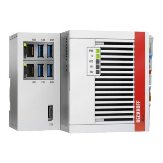
Fig. 1 Example Configuration of a CX5340 Embedded PC
Name Plate
Table 5 Information on the Name Plate
Fig. 2 Name Plate Example
Types
Table 6 Cx53X0, Ordering Information for Software
Fig. 3 Nomenclature for the Cx53X0 Embedded PC
Interface Description
Usb 3.1 (X100, X101, X102, X103)
Table 7 USB Interfaces (X100, X101, X102, X103), Pin Assignment
Fig. 4 USB Interfaces X100, X101, X102, X103
Ethernet RJ45 (X000, X001)
Table 8 Ethernet Interface X000 and X001, Pin Assignment
Fig. 5 Ethernet Interfaces X000, X001
Displayport (X200)
Table 9 Displayport, Pin Assignment
Table 10 Displayport X300, Resolution at the Monitor
Fig. 6 Displayport X300
Optional Interfaces
DVI-D (N010)
Displayport (N011)
Table 11 DVI-D Interface X300, Pin Assignment
Table 12 DVI-D Interface X300, Resolution at the Monitor
Fig. 7 DVI-D Interface X300
Audio Interface (N020)
Table 13 Displayport, Pin Assignment
Table 14 Displayport X300, Resolution at the Monitor
Fig. 8 Displayport X300
Fig. 9 Audio Interface X300, X301, X302
Table 15 Line in /Line out Jack Plugs, Pin Assignment
Fig. 10 Line in / Line out X300, X302 Jack Plugs
Fig. 11 MIC in X301 Jack Plug
Rs232 (N030)
Table 16 RS232 Interface X300, Pin Assignment
Fig. 12 RS232 Interface X300
Rs422/Rs485 (N031)
Table 17 RS422/485 Interface, Pin Assignment
Table 18 Default Setting, RS485 Without Echo with End Point (Terminated)
Fig. 13 RS485 Interface X300
Ethercat Master (M112)
Ethercat Slave (B110)
Table 19 Ethercat Master Interface X300, Pin Assignment
Fig. 14 Ethercat Master Interface X300
Table 20 Ethercat Slave Interface X300, Pin Assignment
Fig. 15 Ethercat Slave Interface X300
PROFIBUS (X310)
Table 21 PROFIBUS Interface X310, Pin Assignment
Table 22 Wire Colors of the PROFIBUS Line
Fig. 16 PROFIBUS Interface X310
Canopen (X510)
Table 23 Canopen Interface X510, Pin Assignment
Fig. 17 Canopen Interface X510
Ethernet (M910)
Table 24 Ethernet Interface, PIN Assignment
Fig. 18 Ethernet Interface M910
Commissioning
Assembly
Permissible Installation Positions
Fig. 19 Cx53X0 Embedded PC, Dimensions
Fig. 20 Cx53X0 Embedded PC, Permitted Installation Position
Fastening to the DIN Rail
Changing the Microsd Card
Changing the Cfast Card
Installing Passive Ethercat Terminals
Fig. 21 Identifying a Passive Ethercat Terminal in Twincat
Fig. 22 Passive Ethercat Terminals, Permissible Installation
Power Supply
Fig. 23 Connections for System Voltage (Us) and Power Contacts (Up)
Connect Embedded PC
UL Requirements
Table 25 Required Wire Cross-Sections and Strip Lengths
Fig. 24 Connection Example with a Cx52X0
Switching on
Fig. 25 UL Label on Cx53X0
Fig. 26 Connection Example for Areas with Special UL Requirements
Switching off
Configuration
Starting the Beckhoff Device Manager
Table 26 Access Data for the Beckhoff Device Manager on Delivery
Twincat
Tree View
Table 27 Key for the Tree View
Fig. 27 Cx53X0 Embedded PC in the Tree View of Twincat 3, with Attached Ethercat Terminals (Left) or Bus Terminals (Right)
Searching for Target Systems
Scanning an Embedded PC
Configuring Ethercat Cable Redundancy
Table 28 Cable Redundancy, Hardware for Sample Configuration
Using a Hardware Watchdog
1-Second UPS (Persistent Variables)
Table 29 Storage Location and Names of the Files in Twincat 3
Fig. 28 Behavior of Systems in the Event of a Power Failure Without and with a 1-Second UPS
BIOS Settings
Fig. 29 Loading a Backup of the Persistent Data. Settings in Twincat 3
Windows Write Filter
Fig. 30 UWF Exception List under Twincat 3
Fb_S_Ups_Bapi
Data Types
Plcappsysteminfo
Error Handling and Diagnostics
Diagnostic Leds
K-Bus
Table 30 Diagnostic Leds in K-Bus Mode
Table 31 K-Bus ERR LED, Fault Indication Sequence through the LED
Table 32 K-BUS ERR LED, Fault Description and Troubleshooting
Table 33 Description of the State Variable Values
Fig. 31 Status Variable for Error Handling and Diagnostics under Twincat
E-Bus
Table 34 Diagnostic Leds in K-Bus Mode
Faults
10 Care and Maintenance
Table 35 Replacement Recommendations for PC Components
Replace the Battery
Cleaning the Embedded PC
11 Decommissioning
Removing Cables
Dismantling the Embedded PC
12 Technical Data
Table 36 Technical Data, Dimensions and Weights
Table 37 Technical Data, General Data
Table 38 Technical Data, I/O Terminals
Table 39 Technical Data, Environmental Conditions
Table 40 Technical Data, Graphic Specifications
Table 41 Technical Data, Interfaces
Table 42 Technical Data, Optional Interfaces
13 Appendix
Accessories
Certifications
Table 43 Microsd Cards
Table 44 Cfast Cards
Support and Service
List of Tables
List of Figures
Advertisement
Quick Links
Download this manual
Manual | EN
CX53x0
Embedded PC
2024-12-03 | Version: 1.0
Table of
Contents
Previous
Page
Next
Page
1
2
3
4
5
Advertisement
Table of Contents
Need help?
Do you have a question about the CX53 0 Series and is the answer not in the manual?
Ask a question
Questions and answers
Related Manuals for Beckhoff CX53 0 Series
Industrial PC Beckhoff CX5130 Manual
Embedded-pc (93 pages)
Industrial PC Beckhoff CX5120 Manual
Cx51x0 series embedded pc (88 pages)
Industrial PC Beckhoff CX56 0 Series Manual
Embedded pc (82 pages)
Industrial PC Beckhoff CX5620 Manual
Embedded pc (82 pages)
Industrial PC Beckhoff CX5630 Manual
Embedded pc (82 pages)
Industrial PC Beckhoff CX5330 Manual
Embedded pc (75 pages)
Industrial PC Beckhoff CX5340 Manual
Embedded pc (75 pages)
Industrial PC Beckhoff CX1010 Series Hardware Documentation
Embedded pc (108 pages)
Industrial PC Beckhoff CX8010 Documentation
Embedded-pc with ethercat slave interface (77 pages)
Industrial PC Beckhoff CX1020 Series Hardware Documentation
Embedded pc (121 pages)
Industrial PC Beckhoff CX1030 Series Hardware Documentation
Embedded pc (121 pages)
Industrial PC Beckhoff CX1030-N Series Hardware Documentation
Embedded pc (121 pages)
Industrial PC Beckhoff CX2000 Series Manual
Embedded pc (79 pages)
Industrial PC Beckhoff CX9020 Manual
Embedded pc (20 pages)
Industrial PC Beckhoff CX9020 Manual
Embedded pc (74 pages)
Industrial PC Beckhoff CX9240 Manual
Embedded pc (55 pages)
This manual is also suitable for:
Cx5330
Cx5340
Table of Contents
Print
Rename the bookmark
Delete bookmark?
Delete from my manuals?
Login
Sign In
OR
Sign in with Facebook
Sign in with Google
Upload manual
Upload from disk
Upload from URL


Need help?
Do you have a question about the CX53 0 Series and is the answer not in the manual?
Questions and answers