Table of Contents
Advertisement
Quick Links
Advertisement
Table of Contents

Related Manuals for HGLRC F4 WING FC


Summary of Contents for HGLRC F4 WING FC
- Page 1 F4 WING FC Manual www.hglrc.com...
-
Page 2: Table Of Contents
Accelerometer calibration steps......................4 Compass Calibration..........................5 VTX serial port use. VTX uses OSD smart audio................6 Mixer................................7 Presets................................8 URAT serial port use..........................9 Configuration tab............................10 Advanced tuning............................11 Check receiver signal..........................12 Modes................................13 OSD settings..............................14 LED settings..............................15 Troubleshooting............................16 ..................Package IncIuded F4 WING FC*1 Accessory Bag*1 www.hglrc.com... -
Page 3: Product Specifications
1.Product Specifications Product parameters Model HGLRC F4 WING Flight Control Weight 19.5g Wingspan Sustain 600-1200mm MPU6000-SPI STM32F405R6T6, 8K Black Box Flash memory 16M Support receiver SBUS .i.BUS .DSMX Input Voltage 2-8S Lipo BEC Output 5V@3A 6V@3A 44*28mm board, 20.5mm Size... -
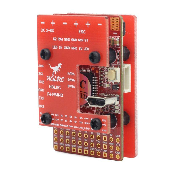
Page 4: Interface Description
2.Interface Description www.hglrc.com... -
Page 5: Check The Flight Control Drive
1. Long Press BOOT buttons.connect USB.The system automatically install the driver 2.Driver cannot be installed, please download ImpulseRC_Driver_Fixer 3.Double-click on the run(Plug in the flight controller to automatically install the driver) 4.open enter DFU mode INAV Configurator “ ”, www.hglrc.com... - Page 6 5.Click Select firmware version 6.Click Load firmware Waiting for completion It will be prompted upon completion 7.open 。 Controller plugged into the computer. INAV INAV Configurator Configurator Automatically assigned port, click“Connect”Enter setup “ ” interface(Different computer COM) www.hglrc.com...
-
Page 7: Accelerometer Calibration Steps
2.Specific calibration please refer to the following picture (for your reference ) 5.Compass Calibration 1. Click on the “Calibrate Magnetometer” button. Then perform compass calibration. Only 30 seconds of calibration time. Pick up the compass and rotate each side (front, rear, left and right). www.hglrc.com... -
Page 8: Vtx Serial Port Use. Vtx Uses Osd Smart Audio
6.VTX serial port use. VTX uses OSD smart audio 1.VTX connection diagram 2.VTX serial port opens. The protocol is selected according to its own VTX protocol. www.hglrc.com... - Page 9 In the “Scr Layout” sub-menu, you can move the OSD elements (like battery voltage, mAh, and so forth) around on the screen. The “Alarms” sub-menu lets you control when the OSD will try to alert you that battery voltage is too low or mAh consumed is too high. www.hglrc.com...
-
Page 10: Mixer
Select a preset from the iNav presets tab that fits your aircraft the best, then press "Apply" 9.URAT serial port use URAT1 uses the DSM2/i.BUS/SmartPort URAT2 uses the VTX URAT3 uses the GPS/Compass URAT4 uses the ESC telemetry URAT6 uses the SBUS www.hglrc.com... -
Page 11: Configuration Tab
By default ("Accelerometer". "Barometer" Sensors) Example 1 I connected Magnetometer (HMC5883) The following picture shows the settings。 Open output Enable motor and servo output。 2.ESC/Motor Features Choose stable ( Oneshot125) ESC protocol. Minimum Throttle ( 1000) Maximum Throttle ( 2000) Minimum Command(1000) www.hglrc.com... - Page 12 3.GPS parameters setting 1. GPS connection diagram 2. Open the GPS serial port 3. Note: Remember to configure a Serial Port (via Ports tab) when using GPS feature. www.hglrc.com...
-
Page 13: Advanced Tuning
4.Check the battery voltage monitoring, the parameters can be ok by default. 11.Advanced tuning 1. Note that the height and distance of the INIV are in centimeters. It is recommended to set the return height to at least 150 meters www.hglrc.com... -
Page 14: Check Receiver Signal
12.Check receiver signal 1. Receiver Connection Diagram 2.Receiver mode select "Serial Receiver SBUS" Serial Receiver Label Select "SBUS" www.hglrc.com... -
Page 15: Modes
1000,the maximum is 2000 (the throttle value can be set minimum 998,the maximum can be set to 2000) 13.Modes 1.set up the function of remote control switch across the channel (below are for reference only) www.hglrc.com... -
Page 16: Osd Settings
14.OSD settings the OSD Settings, according to the need to choose, drag the 1.Click OSD schematic diagram of the parameters can be adjusted. 15.LED settings 1.Click Click set according to need. www.hglrc.com... -
Page 17: Troubleshooting
2. If the product is damaged due to improper operation, the repair service may be provided under the condition that the inspection can be repaired. 3. For domestic customers, please contact the after-sales service personnel. For overseas customers, please contact the official website for after-sales service. www.hglrc.com...
Need help?
Do you have a question about the F4 WING FC and is the answer not in the manual?
Questions and answers