Table of Contents
Advertisement
Quick Links
S O F T W A R E A N D H A R D W A R E S O L U T I O N S F O R T H E E M B E D D E D W O R L D
MikroElektronika
Development tools - Books - Compilers
3
in
MICROCHIP
MICROCHIP
dsPIC
dsPIC
DEVELOPMENT
DEVELOPMENT
BOARD
BOARD
Serial
Serial
Ethernet
Ethernet
SUPPORTED
SUPPORTED
User's Manual
1
USB 2.0
USB 2.0
IN-CIRCUIT
IN-CIRCUIT
PROGRAMMER
PROGRAMMER
Software and Hardware
solutions for Embedded World
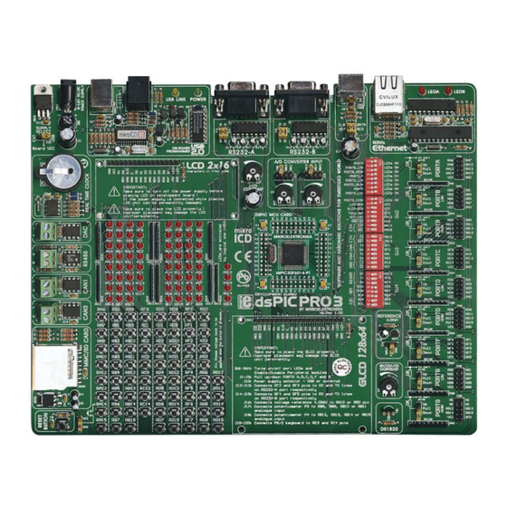
dsPICPRO3
With useful implemented peripherals, many practical
code examples and a broad set of add-on boards (Serial
Ethernet, Compact Flash, MMC/SD, ADC, DAC, CAN,
RTC, RS-485, etc.), MikroElektronika development
boards make fast and reliable tool which can satisfy
needs of experienced engineers and beginners alike.
Advertisement
Table of Contents

Related Manuals for mikroElektronika dsPICPRO3


Summary of Contents for mikroElektronika dsPICPRO3
- Page 1 (Serial Ethernet, Compact Flash, MMC/SD, ADC, DAC, CAN, DEVELOPMENT DEVELOPMENT BOARD BOARD IN-CIRCUIT IN-CIRCUIT RTC, RS-485, etc.), MikroElektronika development PROGRAMMER PROGRAMMER boards make fast and reliable tool which can satisfy needs of experienced engineers and beginners alike. Serial Serial Ethernet...
- Page 2 KEY FEATURES 1. External power supply from 8 to 16 V AC/DC; 2. Choose between external and USB power supply. You don’t need external supply if you powering from PC’s USB port; 3. Very fast and flexible on-board USB program mer with mikroICD (In-Circuit Debugger).
-
Page 3: Table Of Contents
User’s Manual MikroElektronika Development tools CONTENTS CONNECTING THE SYSTEM page 4 INTRODUCTION page 5 DESCRIPTION OF THE DEVELOPMENT SYSTEM page 5 Switches page 6 Jumpers page 7 MCU Card Connector page 8 Power Supply page 11 On-Board USB Programmer... -
Page 4: Connecting The System
Install dsPICFLASH programmer and drivers. Start installation from the product CD: CD_Drive:\product\zip\dsPICFlash_setup.exe. After the installation connect USB cable to the dsPICPRO3 board. You’ll be asked for Step no.3 dsPICFLASH drivers. Point to them in order to finish driver installation. They are placed in the folder: System_Drive:\Program Files\Mikroelektronika\dsPICFLASH\Driver.NT... -
Page 5: Introduction
User’s Manual MikroElektronika Development tools INTRODUCTION MICROCHIP MICROCHIP dsPICPRO3 development system is a full-featured development board for Microchip dsPIC dsPIC dsPIC microcontrollers, designed to enable students and engineers to easily exercise and explore DEVELOPMENT DEVELOPMENT BOARD BOARD the capabilities of dsPIC microcontrollers.It enables dsPIC microco ntrollers to be interfaced with a broad range of peripheral devices, enabling user to concentrate on software develop- ment. -
Page 6: Switches
MikroElektronika Development tools SWITCHES dsPICPRO3 development board features many peripherial devices. In order to enable these devices before programming, you need to check if appropriate jumpers or switches have been properly set. Switches are devices that have two positions - ON and OFF- which have a role to establish or break a connection between two contacts. -
Page 7: Jumpers
User’s Manual MikroElektronika Development tools JUMPERS Jumpers, like switches, can establish or break a connection between two points. Under a plastic cover of jumper is a metal contact which makes a connection when you place jumper between two disconnected pins. -
Page 8: Mcu Card Connector
Development tools MCU CARD dsPICPRO3 development board has 80-pin MCU Card. If you want to use some other microcontroller, all you have to do is to change MCU Cards. dsPICPRO3 MCU Card is shown on the picture below: Figure 5. - Page 9 You have to follow these steps in order to place your MCU Card properly in the dsPICPRO3 MCU socket : Step no.1 If MCU Card has been already placed on dsPICPRO3, you have to remove it by pulling it up slowly. Step no.2 Place MCU Card on the board.
- Page 10 User’s Manual MikroElektronika Development tools Microcontroller pins are routed to various peripherials as illustrated in Fig.6. All ports have direct connections to the Direct Port Access connectors. Such connectors are tipically used to connect external peripherials to the board, or to provide useful points for digital logic probes connection.
-
Page 11: Power Supply
J10 should be set in the right-hand position. In case of external power supply, dsPICPRO3 board produces +5V using LM7805 voltage regulator. External power supply can be AC or DC, with voltage between 8V and 16 V and jumper J10 should be set in the left-hand position. -
Page 12: On-Board Usb Programmer
User’s Manual MikroElektronika Development tools ON-BOARD USB 2.0 PROGRAMMER USB 2.0 USB 2.0 There is no need to use external equipment during programming because dsPICPRO3 IN-CIRCUIT IN-CIRCUIT development system has its own on-board USB 2.0 programmer. PROGRAMMER PROGRAMMER All you need to do is to connect the system to your PC using USB cable. Then, load your program into the microcontroller via dsPICflash programming software which is supplied with the board. -
Page 13: Ds1820 Digital Thermometer
-55°C to 125°C and the accuracy of +/-0.5°C. It must be placed correct- ly in 3-pin socket provided on dsPICPRO3, with its rounded side to the left, as marked on the board (Fig 11). Otherwise DS1820 could be permanently damaged.Switch 4 on SW2... -
Page 14: Leds
LEDs Light Emitting Diodes (LEDs) are most commonly used components, usually for displaying pins digital state. dsPICPRO3 has 67 LEDs connected to microcontroller’s ports- PORTA, PORTB low, PORTB high, PORTC, PORTD low, PORTD high, PORTE low, PORTE high and PORTF. - Page 15 User’s Manual MikroElektronika Development tools All LEDs from one port are connected to the common point through these resistors which can be then connected or disconnected to ground by the corresponding switch on SW1. The LEDs connected to ground are enabled and will display the state of the corresponding micro- controller pin;...
-
Page 16: Pushbutton Switches
User’s Manual MikroElektronika Development tools PUSHBUTTON SWITCHES dsPICPRO3 has 67 push-buttons which can be used to provide digital inputs to microcontroller ports. There is also another pushbutton that acts as a RSTbut RSTbut RESET button (Figure 15). RG15 RC14... - Page 17 User’s Manual MikroElektronika Development tools Example of button connection to PORTD low and PORTD high is shown in Fig.18. Jumper J11 determines whether a button press will bring logical zero or logical one to the appropri- ate pin. When the button is not pressed, the pin state is determined by the pull-up or pull-down port jumpers.
-
Page 18: Graphic Lcd
User’s Manual MikroElektronika Development tools GRAPHIC LCD GRAPHIC LCD GRAPHIC LCD CONNECTOR CONNECTOR Graphic LCD (GLCD) enables advanced visual messages to be displayed. While character LCD can display only alphanumeric characters, GLCD can be used to display messages as... -
Page 19: Lcd 2X16 In 4Bit Mode
User’s Manual MikroElektronika Development tools LCD 2X16 IN 4-BIT MODE 2x16 LCD 2x16 LCD CONNECTOR CONNECTOR Standard character LCD is probably the most widely used data visualization 2x16 LCD 2x16 LCD component.Normally, it can display two lines of 16 alphanumeric characters, each charac-... -
Page 20: Rs-232 Communication
Figure 23. RS232 connectors dsPICPRO3 development board has two RS-232 communication devices, RS-232 A and RS- 232 B. Tx and Rx lines of RS232A are connected to MCU pins via jumpers J13 and J12. Tx and Rx lines of RS232B are connected to MCU pins via jumpers J15 and J14. - Page 21 User’s Manual MikroElektronika Development tools RS232 Receive CONNECT data (Rx) MCU TO PC SERIAL CABLE CONNECT Send PC TO MCU Data (Tx) RS232-A CN12 SUB-D 9p RS232-A is RS232-A is connected disconnected RG15 RC14 RC13 RD11 RD10 RA15 MCLR...
- Page 22 User’s Manual MikroElektronika Development tools RS232 Receive CONNECT data (Rx) MCU TO PC SERIAL CABLE CONNECT Send PC TO MCU Data (Tx) RS232-B CN13 SUB-D 9p RS232-B is RS232-B is disconnected connected RG15 RC14 RC13 RD11 RD10 RA15 MCLR...
-
Page 23: A/D Converter Input
Development tools A-D CONVERTER INPUT ADC INPUT ADC INPUT dsPICPRO3 development board has two potentiometers for working with Analog to Digital Converter (ADC). Both potentiometers outputs are in the range of 0V to 5V. Two analog sig- ENABLED ENABLED nals can be connected on two different analog input pins at the same time.Jumper group J17... - Page 24 User’s Manual MikroElektronika Development tools RG15 RC14 RA10 RC13 Vref+ RD11 RD10 RA15 MCLR RA14 dsPIC30FXXXX OSC2 OSC1/CLKI RA12 RA13 Pull Down 10uF Figure 27. A-D Converter input schematic RB10 RB11 RB12 RB13 RB14 RB15 P10K P10K page 2 2 4 4...
-
Page 25: Ps2 Keyboard Connector
Development tools PS/2 (KEYBOARD) CONNECTOR PS/2 READY PS/2 READY PS/2 connector enables direct connection between dsPICPRO3 and devices that use PS/2 communication, such as PC, keyboard or mouse. For example, microcontroller can be con- DEVELOPMENT DEVELOPMENT nected to keyboard to capture pressed keys. It also can be connected to PC to act as a key- board. -
Page 26: Direct Port Access
User’s Manual MikroElektronika Development tools DIRECT PORT ACCESS All microcontrollers input/output pins can be accessed via connectors placed along the right side of the board. For each of the following pins PORTA, PORTB low, PORTB high, PORTC, PORTD low, PORTD high, PORTF, PORTG low and PORTG high, there is one 10-pin connector providing VCC, GND and up to eight port pins. - Page 27 User’s Manual MikroElektronika Development tools Pull-up line is connected Pull RN5 8X10K Down Pull-down line All lines is connected are disconnected RG15 RC14 RC13 RD11 RD10 RA15 MCLR RA14 dsPIC30FXXXX OSC2 OSC1/CLKI RA12 RA13 10MHz 22pF 22pF HEADER 5x2 Figure 33.
-
Page 28: Mmc/Sd (Multimedia Card)
6 on SW2. By doing that, microcontroller SPI comunnication lines (SDI, SDO and SCK) and Chip Select are connected to MMC. Working voltage of dsPICPRO3 is 5V DC, while working voltage of MMC card is 3.3V DC. Because of that, there is on-board voltage reg- ulator with MMC card (MC33269DT-3.3). - Page 29 User’s Manual MikroElektronika Development tools LED RGH LCD BCK GLCD BCK RG15 RC14 RC13 RTC INT RA12 RD11 MMC CS RD10 ETH INT RA14 ETH WOL RA15 RA15 MCLR RA14 dsPIC30FXXXX OSC2 OSC1/CLKI RT485 RC13 RA12 RA13 TX485 10MHz...
-
Page 30: Serial Ethernet On-Board
User’s Manual MikroElektronika Development tools SERIAL ETHERNET ON BOARD Serial Serial Ethernet Ethernet Ethernet is the most common Local Area Network (LAN) technology in use today. On the top of the physical layer Ethernet stations mutually communicate by sending data packets to... - Page 31 User’s Manual MikroElektronika Development tools VCC3.3 VCC3.3 VCC3.3 VCC3.3 VCC3.3 100nF 100nF 100nF 100nF LD70 LD71 10uF VCC3.3 VCAP VCC3.3 LEDA CLKOUT LEDB INT3.3 OSC-VCC WOL3.3 OSC2 MISO3.3 OSC1 25 MHz MOSI OSC-GND PLL-GND ETH-CS PLL-VCC FERRITE ETH-RST RESET...
-
Page 32: Real Time Clock
User’s Manual MikroElektronika Development tools REAL TIME CLOCK Real-Time Clock (RTC) is an integrated circuit chip that keeps track of the current time even when microcontroller is turned off. Real-time clock runs on a special battery that is not con- nected to the normal power supply. - Page 33 Figure 40b. D/A Converter back dsPICPRO3 has 12-bit output D/A converter MCP3204 with serial interface. In order to enable D/A converter, switches 7 and 8 on SW3 have to be turned on, as well as switches 4, and 6 on SW4, which role is to enable SPI communication between microcontroller and D/A converter.
- Page 34 User’s Manual MikroElektronika Development tools Figure 41. D/A Converter schematic Vref VOUT VREF CONNECTOR LDAC CN17 MCP3204 RG12 ETH-CS RG13 ETH-RST CAN-TX1 RG15 RC14 CAN-RX1 RC13 CAN-TX2 RD11 CAN-RX2 RD10 DAC-LD DAC-CS RA15 MCLR RA14 dsPIC30FXXXX OSC2 OSC1/CLKI RA12...
-
Page 35: Rs485 Communication
Rx and Tx lines to differential sig- nal on A and B output lines. dsPICPRO3 development board has one RS485 communication device. In order to provide more flexible system, microcontroller is connected to LTS485 through three switches on SW4. -
Page 36: Can Communication
Half-duplex means that microcontrollers can send and recieve data, but only in one direction at a time. dsPICPRO3 development board has two CAN communication devices. In order to enable CAN1 communication device, switches 3 and 4 on SW3 have to be turned ON. -
Page 37: Icd2 Connector
User’s Manual MikroElektronika Development tools ICD2 (IN-CIRCUIT DEBUGGER) CONNECTOR ICD2 is a low-cost In-Circuit Debugger (ICD) and In-Circuit Serial Programmer (ICSP). ICD2 is intended to be used as an evaluation, debugging and programming aid in laborato- ry enviroment. The ICD2 offers these features:... - Page 38 None part of this manual, including the product and software described in it, may be repro- duced, transmitted, transcribed, stored in a retrieval system, or translated into any language in any form or by any means, without express written permission of MikroElektronika com- pany, excepting documentation kept the purchaser for backup purposes.
- Page 40 MikroElektronika S O F T W A R E A N D H A R D W A R E S O L U T I O N S F O R T H E E M B E D D E D W O R L D...
Need help?
Do you have a question about the dsPICPRO3 and is the answer not in the manual?
Questions and answers