Autonics TM Series User Manual For Communication
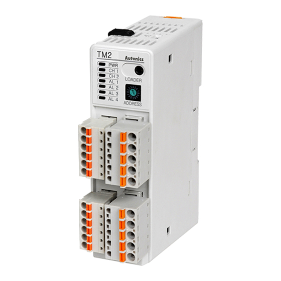
Multi-ch modular type temperature controller
Hide thumbs
Also See for TM Series:
- User manual (98 pages) ,
- Manual (9 pages) ,
- Product manual (4 pages)
Table of Contents
Advertisement
Advertisement
Table of Contents

Related Manuals for Autonics TM Series


Summary of Contents for Autonics TM Series
- Page 1 Preface USER MANUAL For COMMUNICATION © Copyright Reserved Autonics Co., Ltd.
- Page 2 Preface © Copyright Reserved Autonics Co., Ltd.
-
Page 3: Preface
Preface Preface Thank you for purchasing an Autonics product. Please familiarize yourself with the information contained in the Safety Precautions section before using this product. This user manual contains information about the product and its proper use, and should be kept in a place where it will be easy to access. -
Page 4: User Manual Guide
The manual's content may vary depending on changes to the product's software and other unforeseen developments within Autonics, and is subject to change without prior notice. Upgrade notice is provided through out homepage. We contrived to describe this manual more easily and correctly. However, if there are any ... -
Page 5: Communication Protocol
Communication Protocol Communication Protocol TM Series is accepted to Modbus RTU Protocol. Users should be aware that it does not support a broadcast command. © Copyright Reserved Autonics Co., Ltd. -
Page 6: User Manual Symbols
Failure to follow instructions can result in serious injury or death. Failure to follow instructions can lead to a minor injury or product damage. An example of the concerned feature's use. Annotation mark. ※1 © Copyright Reserved Autonics Co., Ltd. -
Page 7: Safety Precautions
Failure to follow this instruction may result in electric shock or fire. Do not use the unit where flammable or explosive gas, humidity, direct sunlight, radiant heat, vibration, or impact may be present. Failure to follow this instruction may result in fire or explosion. © Copyright Reserved Autonics Co., Ltd. - Page 8 For installing the unit with reinforced insulation, use the power supply unit which basic level is ensured. ※ The above specifications are subject to change and some models may be discontinued without notice. VIII © Copyright Reserved Autonics Co., Ltd.
-
Page 9: Table Of Contents
Control setting group(Func: 03/06/16, RW: R/W) ........29 2.5.6 Communication setting group(Func: 03/06/16, RW: R/W) ......30 2.5.7 Alarm setting group (Func: 03/06/16, RW: R/W) ........31 2.5.8 Digital iput setting group (Func: 03/06/16, RW: R/W) ........ 35 © Copyright Reserved Autonics Co., Ltd. - Page 10 Table of Contents © Copyright Reserved Autonics Co., Ltd.
-
Page 11: Modbus Rtu Protocol
“OFF-ON”. Response (Slave) Error check(CRC16) Slave address Function Byte count Data Data High (000008 to 000001) (000010 to 000009) 11 H 01 H 02 H CD H 01 H ## H ## H © Copyright Reserved Autonics Co., Ltd. -
Page 12: Read Input Status(Func 02-02H)
ON”. Response (Slave) Error check(CRC16) Slave address Function Byte count Data Data High (100008 to 100001) (100010 to 100009) 11 H 02 H 02 H CD H 01 H ## H ## H © Copyright Reserved Autonics Co., Ltd. -
Page 13: Read Holding Registers(Func 03-03H)
“100(64 H)”. Response (Slave) Data Data Error check(CRC16) Slave Function Byte count address High High High 11 H 03 H 04 H 02 H 2B H 00 H 64 H ## H ## H © Copyright Reserved Autonics Co., Ltd. -
Page 14: Read Input Registers(Func 04-04H)
“20(14 H)”. Response (Slave) Data Data Error check(CRC16) Slave Function Byte count address High High High 11 H 04 H 04 H 00 H 0A H 00 H 14 H ## H ## H © Copyright Reserved Autonics Co., Ltd. -
Page 15: Force Single Coil (Func 05-05H)
## H Response (Slave) Starting address Preset data Error check (CRC16) Slave address Function High High High 11 H 05 H 00 H 00 H FF H 00 H ## H ## H © Copyright Reserved Autonics Co., Ltd. -
Page 16: Preset Single Registers(Func 06-06H)
## H ## H Response (Slave) Starting address Preset data Error check(CRC16) Slave address Function High High High 11 H 06 H 00 H 00 H 00 H 0A H ## H ## H © Copyright Reserved Autonics Co., Ltd. -
Page 17: Preset Multiple Registers(Func 16-10H)
Please use the Single Register Write function rather than Multi Register Write function if you use the slave(device) connecting with external devices such as PLC, Graphic Panel, except in the case of download that presets the minimum/maximum or basic value of parameter by Input specifications in PC Loader Program © Copyright Reserved Autonics Co., Ltd. -
Page 18: Exception Response-Error Code
03 H E8 H 00 H 01 H ## H ## H Response (Slave) Error check(CRC16) Function Slave address Exception Code +80 H High 11 H 81 H 02 H ## H ## H © Copyright Reserved Autonics Co., Ltd. -
Page 19: Modbus Mapping Table
CH3 auto-tuning 000006(0005) Execute execute/stop 1: ON 0: RUN 000007(0006) CH4 RUN/STOP CH4 control output run/stop 1: STOP 0: OFF CH4 Auto-Tuning CH4 auto-tuning 000008(0007) Execute execute/stop 1: ON 000009(0008) 000009(0008) Reserved 000050(0031) 000050(0031) © Copyright Reserved Autonics Co., Ltd. -
Page 20: Read Input Status (Func: 02, Rw: R)
1: ON - 100008(0007) - AL4 LED 0: OFF 1: ON - 100009(0008) - DI-1 input 0: OFF 1: ON - 100010(0009) - DI-2 input 0: OFF 1: ON - 100011(000A) 100011(000A) Reserved 100050(0031) 100050(0031) © Copyright Reserved Autonics Co., Ltd. -
Page 21: Read Input Register (Func: 04, Rw: R)
Input status quantity Holding register 300122(0079) 300122(0079) 0000 start address 300123(007A) 300123(007A) Holding register quantity Input register start 300124(007B) 300124(007B) 0000 address 300125(007C) 300125(007C) Input register quantity 300126(007D) 300126(007D) Channel quantity 300127(007E) 300127(007E) Reserved 300200(00C7) 300200(00C7) © Copyright Reserved Autonics Co., Ltd. -
Page 22: Read Input Register (Func: 04, Rw: R)
CH4 LED(OUT) 0: OFF 1: ON - Fixed as 0 301025(0400) Fixed as 0 Fixed as 0 Fixed as 0 Fixed as 0 Fixed as 0 301026(0401) 301026(0401) Unit Address Unit address 01 to 31 © Copyright Reserved Autonics Co., Ltd. - Page 23 AL4 LED AL3 LED AL2 LED AL1 LED CH4 LED CH3 LED CH2 LED CH1 LED 0 or 1 0 or 1 0 or 1 0 or 1 0 or 1 0 or 1 0 or 1 0 or 1 1 Byte © Copyright Reserved Autonics Co., Ltd.
-
Page 24: Read Holding Register(Func 03)/Preset Single Register(Func 06)/Preset Multiple Registers(Func 16)
400050(0031) 400050(0031) 401001(03E8) 401001(03E8) CH2 parameter – the same as above CH1 401050(0419) 401050(0419) 402001(07D0) CH3 parameter - the same as above CH1 402050(0801) 403001(0BB8) CH4 parameter - the same as above CH1 403050(0BE9) © Copyright Reserved Autonics Co., Ltd. -
Page 25: Control Operation Group(Func : 03/06/16, Rw : R/W)
400200(00C7) 400100(0063) 401101(044C) 401051(041A) CH2 parameter – the same as above CH1 401200(04AF) 401100(044B) 402051(0802) CH3 parameter - the same as above CH1 402100(0833) 403051(0BEA) CH4 parameter - the same as above CH1 403100(0C1B) © Copyright Reserved Autonics Co., Ltd. -
Page 26: Control Operation Group(Func: 03/06/16, Rw: R/W)
Heating & -100.0 to 0.0 -100.0 Cooling MV Low Heating, Limit + 0.1 to 100.0 Cooling MV high-limit 100.0 400215(00D6) 400115(0072) CH1 MV High Limit setting value Heating & 0.0 to 100.0 100.0 Cooling © Copyright Reserved Autonics Co., Ltd. - Page 27 400150(0095) 401201(04B0) 401101(044C) CH2 parameter - the same as above CH1 401300(0513) 401150(047D) 402101(0834) CH3 parameter - the same as above CH1 402150(0865) 403101(0C 1C) CH4 parameter - the same as above CH1 403150(0C4D) © Copyright Reserved Autonics Co., Ltd.
-
Page 28: Initial Setting Group(Func: 03/06/16, Rw: R/W)
400400(0189) 400200(00C7) 401301(00514) 401151(047E) CH2 Parameter - the same as above CH1 401400(0577) 401200(04AF) 402151(0866) CH3 Parameter - the same as above CH1 402200(0897) 403151(0C4E) CH4 Parameter - the same as above CH1 403200(0C7F) © Copyright Reserved Autonics Co., Ltd. -
Page 29: Control Setting Group(Func: 03/06/16, Rw: R/W)
400500(01F3) 400250(00F9) 401401(0578) 401201(04B0) CH2 parameter - the same as above CH1 401500(05DB) 401250(04E1) 402201(0898) CH3 parameter - the same as above CH1 402250(08C9) 403201(0C80) CH4 parameter - the same as above CH1 403250(0CB1) © Copyright Reserved Autonics Co., Ltd. -
Page 30: Communication Setting Group(Func: 03/06/16, Rw: R/W)
Response Waiting 400604(025B) 400304(012F) 5 to 99 Time waiting time 0: ENABLE Communication Communication 400605(025C) 400305(0130) Write write 1: DISABLE Parameter 400606(025D) 400306(0131) Parameter Initialize 0: NO 1: YES initialization 400607(025E) 400307(0132) Reserved 400700(02BB) 400350(015D) © Copyright Reserved Autonics Co., Ltd. -
Page 31: Alarm Setting Group (Func: 03/06/16, Rw: R/W)
LBA1 Ch2 400518(0205) - ℃/℉ 3 detection band 0.0 to 999.9 (L) 0: CH1 1: CH2 Alarm2 Alarm output 2 400519(0206) - 2: CH1 or CH2 Target Ch target Ch 4: CH1 and CH2 © Copyright Reserved Autonics Co., Ltd. - Page 32 Ch 4: CH1 and CH2 0: OFF 1: AL-1 2: AL-2 3: AL-3 4: AL-4 5: AL-5 Alarm3 Alarm output 3 400358(0219) - Mode operation mode 6: AL-6 7: LBA 8: SBA 9: HBA © Copyright Reserved Autonics Co., Ltd.
- Page 33 3 : AL-D 4 : AL-E 5 : AL-F Deviation alarm: -F.S to F.S Alarm output 4 Alarm4 ℃/℉ 400558(022D) - Ch1 low-limit 1550 Absolute value alarm: Within the Low_Ch1 value temperature range of input type © Copyright Reserved Autonics Co., Ltd.
- Page 34 LBA4 Time LBA4 Ch2 400570(0239) - 0 to 9999 Sec. 0 monitoring time 400571(023A) - Reserved 0 to 999 (H) LBA4 Band LBA4 Ch2 400572(023B) - ℃/℉ 3 detection band 0.0 to 999.9 (L) © Copyright Reserved Autonics Co., Ltd.
-
Page 35: Digital Iput Setting Group (Func: 03/06/16, Rw: R/W)
Digital input terminal 1 400575(024E) - Digital Input 1 Ch 0: CH1 1: CH2 target channel Digital input terminal 2 400576(024F) - Digital Input 2 Ch 0: CH1 1: CH2 target channel 400577(0250) Reserved 400600(0257) © Copyright Reserved Autonics Co., Ltd. - Page 36 2 Modbus Mapping Table © Copyright Reserved Autonics Co., Ltd. MCT-TMC1-V1.5-1712US...
Need help?
Do you have a question about the TM Series and is the answer not in the manual?
Questions and answers