Autonics TM Series User Manual
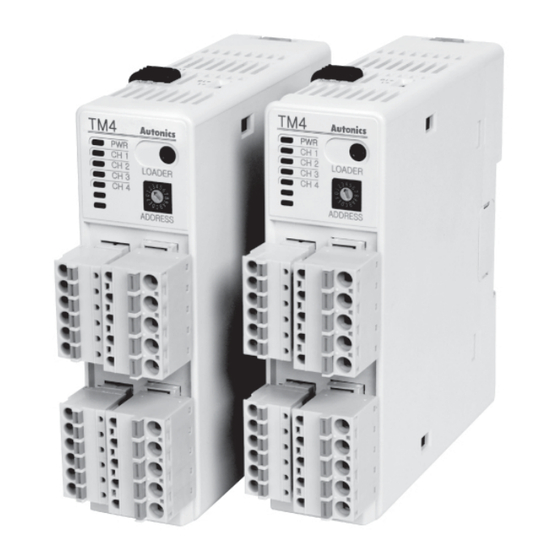
Multi-channel modular temperature controller
Hide thumbs
Also See for TM Series:
- User manual (98 pages) ,
- User manual for communication (36 pages) ,
- Manual (9 pages)
Table of Contents
Advertisement
Quick Links
Advertisement
Table of Contents

Subscribe to Our Youtube Channel
Related Manuals for Autonics TM Series


Summary of Contents for Autonics TM Series
- Page 1 User Manual For Communication...
- Page 2 © Copyright Reserved Aotonics Co., Ltd.
-
Page 3: Preface
Preface Preface Thank you for purchasing an Autonics product. Please store this manual in a place where user can find easily, because it contains the guidance for the product and how to correctly use it. © Copyright Reserved Aotonics Co., Ltd. -
Page 4: User Manual Guide
The manual's content may vary depending on changes to the product's software and other unforeseen developments within Autonics, therefore, the contents of this manual is subject to change without prior notice. © Copyright Reserved Aotonics Co., Ltd. -
Page 5: Communication Protocol
Communication Protocol Communication Protocol TM Series is accepted to Modbus RTU Protocol. Users should be aware that it does not support a broadcast command. © Copyright Reserved Aotonics Co., Ltd. - Page 6 Communication Protocol © Copyright Reserved Aotonics Co., Ltd.
-
Page 7: Table Of Contents
Alarm Setting Group(1) (Func: 03/06/16, RW: R/W) ........29 2.5.8 Alarm Setting Group(2) (Func: 03/06/16, RW: R/W) ........31 2.5.9 Alarm Setting Group(3) (Func: 03/06/16, RW: R/W) ........33 2.5.10 Option(Digital Input Setting) Group (Func: 03/06/16, RW: R/W) ....34 © Copyright Reserved Autonics Co., Ltd. -
Page 8: Table Of Contents
Table of Contents viii © Copyright Reserved Autonics Co., Ltd. -
Page 9: Modbus Rtu Protocol
ON-OFF-OFF-ON-ON-OFF-ON”, and the values from 000010(0009 H) to 000009(0008 H) are respectively “OFF-ON”. Response (Slave Side) Error Check(CRC16) Slave Data Data Function Byte Count Address High (000008~000001) (000010~000009) 11 H 01 H 02 H CD H 01 H ## H ## H © Copyright Reserved Autonics Co., Ltd. -
Page 10: Read Input Status(Func 02-02H)
OFF-ON-ON-OFF-ON”, and the values of 100010(0009 H) and 100009(0008 H) are respectively “OFF-ON”. Response (Slave Side) Error Check(CRC16) Slave Data Data Function Byte Count Address (100008~100001) (100010~100009) High 11 H 02 H 02 H CD H 01 H ## H ## H © Copyright Reserved Autonics Co., Ltd. -
Page 11: Read Holding Registers(Func 03-03H)
Response (Slave Side) Data Data Error Check(CRC16) Slave Function Byte Count Address High High High 11 H 03 H 04 H 02 H 2B H 00 H 64 H ## H ## H © Copyright Reserved Autonics Co., Ltd. -
Page 12: Read Input Registers(Func 04-04H)
Response (Slave Side) Data Data Error Check(CRC16) Slave Function Byte Count Address High High High 11 H 04 H 04 H 00 H 0A H 00 H 14 H ## H ## H © Copyright Reserved Autonics Co., Ltd. -
Page 13: Preset Single Registers(Func 06-06H)
## H Response (Slave Side) Starting Address Preset Data Error Check(CRC16) Slave Function Address High High High 11 H 06 H 00 H 00 H 00 H 0A H ## H ## H © Copyright Reserved Autonics Co., Ltd. -
Page 14: Preset Multiple Registers(Func 16-10H)
PLC, Graphic Panel, except in the case of download that presets the minimum/maximum or basic value of parameter by Input specifications in PC Loader Program © Copyright Reserved Autonics Co., Ltd. -
Page 15: Exception Response-Error Code
E8 H 00 H 01 H ## H ## H Response (Slave Side) Error Check(CRC16) Function Slave Exception Code Address +80 H High 11 H 81 H 02 H ## H ## H © Copyright Reserved Autonics Co., Ltd. - Page 16 1 Modbus RTU Protocol © Copyright Reserved Autonics Co., Ltd.
-
Page 17: Modbus Mapping Table
000006(0005) CH3 Auto-Tuning Execute Execute/Stop 1: ON 0: RUN 000007(0006) CH4 RUN/STOP CH4 Control Output Run/Stop 1: STOP 0: OFF CH4 Auto-Tuning 000008(0007) CH4 Auto-Tuning Execute Execute/Stop 1: ON 000009(0008) 000009(0008) Reserved 000050(0031) 000050(0031) © Copyright Reserved Autonics Co., Ltd. -
Page 18: Read Input Status (Func: 02, Rw: R)
1: ON 100007(0006) AL3 LED 0: OFF 1: ON 100008(0007) AL4 LED 0: OFF 1: ON 100009(0008) DI-1 Input 0: OFF 1: ON 100010(0009) DI-2 Input 0: OFF 1: ON 100011(000A) 100011(000A) Reserved ~100050(0031) ~100050(0031) © Copyright Reserved Autonics Co., Ltd. -
Page 19: Read Input Register (Func: 04, Rw: R)
Input status Quantity Holding Register 300122(0079) 300122(0079) 0000 Start Address 300123(007A) 300123(007A) Holding Register Quantity 300124(007B) 300124(007B) Input Register Start Address 0000 300125(007C) 300125(007C) Input Register Quantity 300126(007D) 300126(007D) Channel Quantity 300127(007E) 300127(007E) Reserved ~300200(00C7) ~300200(00C7) © Copyright Reserved Autonics Co., Ltd. -
Page 20: Read Input Register (Func: 04, Rw: R)
1: ON CH4 LED(OUT) 0: OFF 1: ON Fixed as 0 301025(0400) Fixed as 0 Fixed as 0 Fixed as 0 Fixed as 0 Fixed as 0 301026(0401) 301026(0401) Unit Address Unit Address 01~31 © Copyright Reserved Autonics Co., Ltd. - Page 21 CH4 LED CH3 LED CH2 LED CH1 LED 0 or 1 0 or 1 0 or 1 0 or 1 0 or 1 0 or 1 0 or 1 0 or 1 1 Byte © Copyright Reserved Autonics Co., Ltd.
-
Page 22: Read Holding Register(Func 03)/Preset Single Register(Func 06)/Preset Multiple Registers(Func 16)
~400050(0031) ~400050(0031) 401001(03E8) 401001(03E8) CH2 Parameter – the same as above CH1 ~401050(0419) ~401050(0419) 402001(07D0) CH3 Parameter - the same as above CH1 ~402050(0801) 403001(0BB8) CH4 Parameter - the same as above CH1 ~403050(0BE9) © Copyright Reserved Autonics Co., Ltd. -
Page 23: Operating(Control Operation) Group(Func : 03/06/16, Rw : R/W)
~400200(00C7) ~400100(0063) 401101(044C) 401051(041A) CH2 Parameter – the same as above CH1 ~401200(04AF) ~401100(044B) 402051(0802) CH3 Parameter - the same as above CH1 ~402100(0833) 403051(0BEA) ~403100(0C1 CH4 Parameter - the same as above CH1 © Copyright Reserved Autonics Co., Ltd. -
Page 24: Control Operation Group(Func: 03/06/16, Rw: R/W)
400218(00D9) 400118(0075) CH1 Ramp Time Unit Ramp Time Unit 0: SEC 1: MIN 2: HOUR - 400219(00DA) 400119(0076) CH1 Reserved ~400300(012B) ~400150(0095) 401201(04B0) 401101(044C) CH2 Parameter - the same as above CH1. ~401300(0513) ~401150(047D) © Copyright Reserved Autonics Co., Ltd. - Page 25 2 Modbus Mapping Table No(Address) Factory Parameter Description Setting Range Unit Default 402101(0834) CH3 Parameter - the same as above CH1. 402150(0865) 403101(0C 1C) CH4 Parameter - the same as above CH1. 403150(0C4D) © Copyright Reserved Autonics Co., Ltd.
-
Page 26: Initial Setting 그룹(Func: 03/06/16, Rw: R/W)
401301(00514) 401151(047E) CH2 Parameter - the same as above CH1. ~401400(0577 ~ 401200(04AF) 402151(0866) CH3 Parameter - the same as above CH1. ~ 402200(0897) 403151(0C4E) CH4 Parameter - the same as above CH1. ~403200(0C7F) © Copyright Reserved Autonics Co., Ltd. -
Page 27: Control Setting Group(Func: 03/06/16, Rw: R/W)
~400500(01F3) ~400250(00F9) 401401(0578) 401201(04B0) CH2 Parameter - the same as above CH1. ~401500(05DB ~401250(04E1) 402201(0898) CH3 Parameter - the same as above CH1. ~402250(08C9) 403201(0C80) CH4 Parameter - the same as above CH1. ~403250(0CB1 © Copyright Reserved Autonics Co., Ltd. -
Page 28: Option Setting(Communication Setting) Group(Func: 03/06/16, Rw: R
Response Waiting 400604(025B) 400304(012F) 5~99 Time Waiting Time 0: ENABLE Communication 400605(025C) 400305(0130) Communication Write ENABLE Write 1: DISABLE Parameter 400606(025D) 400306(0131) Parameter Initialization 0: NO 1: YES Initialization 400607(025E) 400307(0132) Reserved ~400700(02BB) ~400350(015D) © Copyright Reserved Autonics Co., Ltd. -
Page 29: Alarm Setting Group(1) (Func: 03/06/16, Rw: R/W)
1~999(Sensor. H) 400518(0205) LBA1 Band_ Ch2 LBA1 Ch2 Detecting Band ℃/℉ 0.1~999.9(Sensor. L) Alarm Output 2 Target 0: CH1 1: CH2 2: CH1 or CH2 400519(0206) Alarm2 Target CH Channel 4 : CH1 and CH2 © Copyright Reserved Autonics Co., Ltd. - Page 30 ℃/℉/A 1550 limit Setting Value Sensor Input Range Deviation Alarm: -F.S ~ F.S Alarm Output 2 Ch2 High- 400525(020C) Alarm2 High_Ch2 Absolute Value Alarm: within the 1550 ℃/℉ limit Setting Value Sensor Input Range © Copyright Reserved Autonics Co., Ltd.
-
Page 31: Alarm Setting Group(2) (Func: 03/06/16, Rw: R/W)
Setting Value Sensor Input Range Alarm Output 3 Ch1 1~100 (Sensor. H) 400544(021F) Alarm3 Hysteresis_Ch1 Digit Hysteresis 0.1~100.0 (Sensor. L) Alarm Output 3 Ch2 1~100 (Sensor. H) 400545(0220) Alarm3 Hysteresis_Ch2 Digit Hysteresis 0.1~100.0 (Sensor. L) © Copyright Reserved Autonics Co., Ltd. - Page 32 LBA3 Time_Ch2 LBA3 Ch2 Detecting Time 0~9999 초 LBA3 Ch2 Detecting 1~999(Sensor. H) 400553(0228) LBA3 Level_Ch2 ℃/℉ 8 Value 0.1~999.9(Sensor. L) 1~999(Sensor. H) 400554(0229) LBA3 Band_Ch2 LBA3 Ch2 Detecting Band ℃/℉ 3 0.1~999.9(Sensor. L) © Copyright Reserved Autonics Co., Ltd.
-
Page 33: Alarm Setting Group(3) (Func: 03/06/16, Rw: R/W)
1: STOP 2: AL-RESET 400573(023C) Digital Input 1 Func Function 3 : MANUAL 4: MULTI-SV Digital Input Terminal 2 0: OFF 1: STOP 2: AL-RESET 400574(023D) Digital Input 2 Func Function 3: MANUAL 4: MULTI-SV © Copyright Reserved Autonics Co., Ltd. -
Page 34: Option(Digital Input Setting) Group (Func: 03/06/16, Rw: R/W)
2 Modbus Mapping Table No(Address) Factory Parameter Description Setting Range Unit Default Digital Input Terminal 1 0: CH1 400575(023E) Digital Input 1_Ch STOP Target Channel 1: CH2 0: CH1 Digital Input Terminal 2 400576(023F) Digital Input 2_Ch AL-RESET Target Channel 1: CH2 400577(0240) Reserved...
Need help?
Do you have a question about the TM Series and is the answer not in the manual?
Questions and answers