Table of Contents
Advertisement
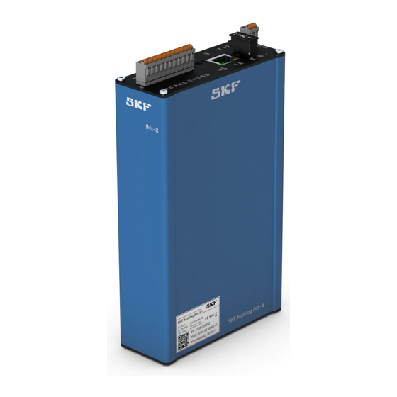
SKF Multilog On-line System
IMx-8/IMx-8Plus
User Manual
Part Number 15V-090-00049-100
Revision E – September 2020
Read this manual carefully before using the product. Failure
to follow the instructions and safety precautions in this manual can
result in serious injury, damage to the product or incorrect
readings. Keep this manual in a safe location for future reference.
Copyright © 2018 by SKF Group
All rights reserved.
SKF Sverige AB
Aurorum 30, 977 75 Luleå, Sweden
Telephone: +46 (0) 31 337 10 00
Advertisement
Table of Contents

Related Manuals for SKF IMx-8


Summary of Contents for SKF IMx-8
- Page 1 Keep this manual in a safe location for future reference. Copyright © 2018 by SKF Group All rights reserved. SKF Sverige AB Aurorum 30, 977 75 Luleå, Sweden...
- Page 3 SKF reserves the right to alter any part of this publication without prior notice. Patents: US , •...
- Page 4 – SKF's Technical Support Group can be reached during normal business hours Technical Support via phone, e-mail and live chat. Always check the self-service web portal before contacting your nearest Technical Support Group (TSG) to see if the answer is already published. You may search...
-
Page 5: Table Of Contents
Table of contents Product description ............... 9 SKF Multilog On-line System IMx-8/IMx-8Plus ..........9 Differences between the IMx-8 and the IMx-8Plus ........9 System communications ................11 1.3.1 Mobile data ..................11 1.3.2 Local network RJ45 or Wi-Fi module ..........11 1.3.3... - Page 6 2.9.5 RS485 Modbus RTU communications........... 43 2.9.6 Connections to Monitor ..............44 Product specifications ..............45 Product labelling ................... 45 SKF Multilog On-line System IMx-8/IMx-8Plus ..........46 3.2.1 Environmental ................46 3.2.2 Power ..................... 46 3.2.3 Analogue inputs ................46 3.2.4...
- Page 7 3.2.14 Quality control ................51 Connector details ..................52 3.3.1 IMx-8 top end cap ................52 3.3.2 IMx-8 bottom end cap ..............53 3.3.3 IMx-8Plus top end cap ..............54 3.3.4 IMx-8Plus bottom end cap ............. 55 Enclosure and cabinet mechanical drawings ..........56 3.4.1...
-
Page 9: Product Description
Wi-Fi Ethernet (RJ45) Simplified overviews of IMx-8 and IMx-8Plus systems are shown in Figures 1 and 2 below, details of the specific features and capabilities follow. Note that in practice @ptitude Observer software will usually be communicating with multiple IMx devices of various types. - Page 10 If required, the RS485 link can interface by Modbus RTU to an external, optional, GPS module. A Bluetooth dongle provides a convenient means of accessing the IMx, from the SKF Multilog IMx Manager app. This app is used for a SAT (Site Acceptance Test), device network configuration and is the companion app if the IMx is used in stand-alone mode.
-
Page 11: System Communications
Similarly to mobile data, an external antenna is required for Wi-Fi, the optional antenna offered by SKF (1.5) fulfils both roles. An RJ45 Ethernet connection is the only network interface built-in to an IMx-8. SKF Multilog On-line System IMx-8/IMx-8Plus... -
Page 12: Bluetooth
As supplied, a Bluetooth dongle specifically configured by SKF is already mounted in the IMx USB Type-A port. Bluetooth is used for communication between the IMx and the SKF Multilog IMx Manager app. This is particularly useful when the IMx is in stand-alone and SAT mode but works in all modes. -
Page 13: Outer Cabinet (Optional)
“General Modbus Protocol Considerations for IMx Devices”. 1.4 Outer cabinet (optional) Where the IMx-8 is not located in an existing cabinet, outer cabinets are available, 3.4.2, to house it and any supporting electronics, provide cable gland areas for sensor, antenna, the GPS and other cables. -
Page 14: External Antenna For Mobile Data/Wi-Fi (Optional)
Important - All unused cable openings must remain closed with blind plugs. 1.5 External antenna for mobile data/Wi-Fi (optional) For use with an IMx-8Plus, SKF offer an optional external antenna that supports both Wi-Fi and mobile data connectivity, noting that the mobile data and Wi-Fi interfaces cannot be used simultaneously. -
Page 15: Installation And Operating Instructions
Observe all site safety requirements including any that may be specific to the machines or areas where the installation work is being carried out. Make sure that the power is disconnected before the installation begins. SKF Multilog On-line System IMx-8/IMx-8Plus 15 (63) User Manual... -
Page 16: Mounting The Imx-8/Imx-8Plus
The IMx-8/IMx-8Plus have a blue, painted aluminium enclosure that is IP30 classified. To provide higher environmental protection, they should be mounted inside a cabinet: an IP65 classified cabinet can be provided by SKF. When using any outer cabinet, always use all the recommended fixings to mount and secure it. - Page 17 INSTALLATION AND OPERATING INSTRUCTIONS Mounting the IMx-8/IMx-8Plus Like the IMx-16 variants, the IMx-8/IMx-8Plus are designed to be DIN rail mounted, Figure 3 above, shows an IMx device DIN rail mounted in a SKF IP65 classified cabinet. The IMx is mounted using the DIN rail bracket attached to the rear face of the device, Figure 4 below.
-
Page 18: Power Requirements
IMx. 2.3 Power requirements The SKF Multilog IMx-8/IMx-8Plus are designed to be powered from a 22 to 50 V DC supply, typical power consumption 10 W or lower. The supply to the device should be fused at 2 A, slow-blow, refer 3.2.2. - Page 19 (for example, a nylon cable tie CV-100K) close to the power connections, at the IMx. Figure 5 Example of securing positive and return wires with a cable tie SKF Multilog On-line System IMx-8/IMx-8Plus 19 (63) User Manual Revision E...
-
Page 20: Site Cabling Considerations
Any unused cable entries must remain closed off. Refer also to the instruction manual: ‘Attaching Sensors for SKF Multilog On-Line Systems’. This provides examples of monitoring scenarios (typical number and location of sensors) as well as important guidance regarding the fitting of sensors. -
Page 21: Ethernet Cabling
RS485 and serial communications links. 2.5 SKF Multilog On-line System IMx-8/IMx-8Plus 2.5.1 Introduction An overview of the capabilities of the IMx-8 and IMx-8Plus was given in section 1 and details of those follow. 2.5.2 Network configuration Network configuration applies to the connection between the IMx device and @ptitude Observer. -
Page 22: Ethernet Connection
LED will flicker when there is traffic on the network. Figure 6 IMx RJ45 Ethernet connector Both the IMx-8 and the IMx-8Plus support Power over Ethernet, PoE, <13 W. PoE can be used instead of or redundantly with the ‘normal’ 24 to 48 V DC supply. •... -
Page 23: Rs485 Modbus Connections
SKF Multilog On-line System IMx-8/IMx-8Plus Figure 7 SIM card orientation 2.5.5 RS485 Modbus connections The IMx-8/IMx-8Plus both have one, 2-wire, RS485 port. For this there are considerations related to grounding and bus termination, Figure Figure 8 Modbus Bus Connection and End Termination *G/G3 (Ground): Devices connected to the bus must have the same ground potential. -
Page 24: Led Indicators
Note that there is no built-in termination that can be activated by configuration. An external resistor of 120 ohms is provided by SKF as well as double deck terminals to facilitate its installation. This resistor is colour-coded black,... -
Page 25: Connecting Accelerometers (A1 To A8)
4-20 mA signal is connected to. SKF provide 250-ohm load resistors for this purpose and double deck connectors to facilitate the installation. These SKF provided resistors must be used and are colour-... -
Page 26: Connecting Tacho/Speed Signals (D1 To D2)
A sensor with suitable sensing range must be selected and gapped appropriately to accommodate any movement between sensor and target, that might occur. The IMx-8/IMx-8Plus support two-wire, three-wire PNP and pulse sources*. *The digital input and trigger characteristics are specified in 3.2.4. Suitable pulse sources include, for example, a TTL like signal of 0 to 5 V and 50% duty cycle or other positive pulse sources up to 24 V. - Page 27 INSTALLATION AND OPERATING INSTRUCTIONS SKF Multilog On-line System IMx-8/IMx-8Plus By design, the IMx-8/IMx-8Plus supply power to both digital input channels, on terminals P1 and P2. Sensor power at P1 and P2 is always enabled and cannot be controlled or configured by hardware or software. Trigger level and hysteresis are also fixed, refer specifications, 3.2.4.
- Page 28 INSTALLATION AND OPERATING INSTRUCTIONS SKF Multilog On-line System IMx-8/IMx-8Plus Figure 14 IMx powered, 3-wire PNP sensor connected to digital input 2 Figure 15 Unpowered or externally powered pulse source, 2-wire, connected to digital input 1 SKF Multilog On-line System IMx-8/IMx-8Plus...
- Page 29 INSTALLATION AND OPERATING INSTRUCTIONS SKF Multilog On-line System IMx-8/IMx-8Plus Table 3 Summary of typical connection arrangements for digital inputs and sensors Sensor type Wire colour Wire function Digital input 2-wire White – IMx powered Black 3-wire PNP Brown IMx powered...
-
Page 30: Connecting Relays
SKF Multilog On-line System IMx-8/IMx-8Plus 2.5.11 Connecting relays The IMx-8/IMx-8Plus each have three relay driver outputs that can be used for remote indication of System status, Warning (Alert) and Alarm (Danger), conditions. The output terminals for these are situated on the bottom end cap of the IMx, refer section 3.3. -
Page 31: System Commissioning And Security
(*in practice this may mean company, operating division, location/site, etc., depending on how registration is organised). When a company first uses an IMx system, SKF will provide one or more user admin accounts to that company. Such admins will have sufficient rights, be aware of the procedure and be responsible for onboarding further company users via the SKF Enlight Centre, user management system. -
Page 32: Imx-8/Imx-8Plus Stand-Alone Mode
SKF Multilog On-line System IMx-8/IMx-8Plus 2.5.13 IMx-8/IMx-8Plus Stand-alone mode The IMx-8/IMx-8Plus can be configured to be used in stand-alone mode. In this scenario, a connection to the @ptitude Observer Monitor Service is not required as data is not transferred for trending and analysis by the @ptitude Observer Client. -
Page 33: Storage Capacity
2.5.16 Storage capacity As noted in the specifications, each IMx-8/IMx-8Plus device has 4 GB effective flash, non-volatile, storage used for the following: •... -
Page 34: Hardware Maintenance
• 2 GB reserved for future development/needs 2.6 Hardware Maintenance The IMx-8/IMx-8Plus hardware, i.e. IMx device and its associated sensors, are virtually maintenance free, though a yearly inspection of all installed equipment is advised. The IMx device does not need to be opened for hardware maintenance or inspection, in case of suspected hardware failure;... -
Page 35: Gps Module (Optional)
An external GPS module is available as an option. When fitted, GPS data can be requested by the IMx-8/IMx-8Plus, via Modbus RTU, over the RS485 2-wire connection. On this interface the IMx is the master device and the GPS module, the slave device. -
Page 36: Troubleshooting
Troubleshooting 2.9 Troubleshooting 2.9.1 Introduction This section is intended as an aid to fault finding, on an IMx-8/IMx-8Plus system. It is designed for instrumentation engineers and others with sufficient knowledge of electrical troubleshooting including safe working procedures, in electronic systems powered by 22 to 50 V DC*. -
Page 37: Sensor Circuits
• Incorrectly mounted or loose sensor • Excitation of sensor mounted resonance • Signal disturbance due to external noise, for example RFI • A grounding issue SKF Multilog On-line System IMx-8/IMx-8Plus 37 (63) User Manual Revision E... - Page 38 Did the voltage rise to normal open circuit voltage? NO: The IMx is not providing sensor power. Check that the IMx is correctly configured to supply sensor power for this channel. If SKF Multilog On-line System IMx-8/IMx-8Plus 38 (63) User Manual...
- Page 39 (typically 21 mA) to signal a sensor/circuit failure. In such circumstances the output current will be different to the source, measurement value. Channels where the input signal is 4-20 mA, should have an SKF provided, 250-ohm load resistor fitted, refer section 2.5.9.
- Page 40 IMx and verify that the connections are correct. If all appears OK, measure the DC voltage (V) across the channel input using a digital voltmeter. Is the voltage as expected, for the connected signal, type? NO: Continue to step 2. SKF Multilog On-line System IMx-8/IMx-8Plus 40 (63) User Manual Revision E...
- Page 41 Is the measured voltage now as expected, typically 24 V DC? YES: Double check that the sensor is compatible, especially that the sensor current requirement is within the capability of the IMx. SKF Multilog On-line System IMx-8/IMx-8Plus 41 (63) User Manual...
-
Page 42: Relay Driver Outputs
YES: Measure the DC voltage at the relay coil terminals, using a digital voltmeter. a. Is the measured voltage as expected, approximately 24 V DC? YES: Skip to step 3. SKF Multilog On-line System IMx-8/IMx-8Plus 42 (63) User Manual Revision E... -
Page 43: Rs485 Modbus Rtu Communications
RS485 connections. Bear in mind if there are multiple issues, say a configuration problem and an incorrect connection, all issues will have to be solved before a SKF Multilog On-line System IMx-8/IMx-8Plus 43 (63) User Manual... -
Page 44: Connections To Monitor
The status of the connection to the @ptitude Observer Monitor server (connected or not) is reflected by bit 14 of the Modbus register 30029 (refer to the Modbus for SKF IMx and @ptitude Observer user manual, part number 15V-090-00051-100). This can be especially useful to verify current connection status in any applications, such as mobile or marine, where a continuously available connection is not expected. -
Page 45: Product Specifications
The QR code contains the product information shown alongside it. Note that for the IMx-8Plus, the same MAC address applies to whichever of the local network interfaces is enabled, RJ45 or Wi-Fi. Manufacturing data label – IMx-8 example Figure 17 Manufacturing data label – IMx-8Plus example... -
Page 46: Skf Multilog On-Line System Imx-8/Imx-8Plus
Height does not include terminal connectors and Bluetooth dongle Depth does not include the DIN rail mounting bracket • Device weights: IMx-8: 465 g (1.03 lb) and IMx-8Plus: 580 g (1.28 lb) • IP ratings: IP30, for the DIN rail mounted enclosure... -
Page 47: Digital Inputs
Two digital inputs, non-isolated, referenced to chassis/enclosure ground Accepts positive voltages: up to 24V ▪ Contact SKF for advice if the digital signal may exceed +27 V Trigger level: 2.9 V, Hysteresis 0.1 V, Impedance 1.6 kΩ • Can interface to:... -
Page 48: Signal Processing
Detection of sensor and cable fault • Watchdog and self-testing 3.2.9 Interfaces • The IMx-8 incorporates only an Ethernet, RJ45, interface. For the IMx-8Plus, the mobile data and Ethernet interfaces are alternatives and cannot be used concurrently • Mobile data (IMx-8Plus only) LTE (4G) and legacy 2G/3G networks ▪... -
Page 49: Storage Capacity
EMC emission in compliance with EN 61000-6-4:2007/A1:2011 • DNV GL Renewables certificate – valid only when the IMx-8 DIN rail version is mounted in an IP65 cabinet in a wind turbine that is built according to the DNV GL wind turbine type approval •... - Page 50 PRODUCT SPECIFICATIONS SKF Multilog On-line System IMx-8/IMx-8Plus FCC Part 15B 107/109, ICES-003, FCC Part 15C 15.247 (d), RSS-447 sect. 5.55.5 FCC Part 22H 917/RSS-132 sect. 5.5, FCC Part 24E 328/RSS-133, FCC Part 25.53(h)/RSS-139 FCC compliance statement This device complies with part 15 of the FCC Rules. Operation is subject to the following two conditions: 1.
-
Page 51: Quality Control
DNV GL wind turbine type approval • Marine type approvals DNV GL Lloyd’s Register BIPM: International Bureau of Weights and Measures 3.2.14 Quality control • SKF Sverige AB, Luleå is ISO 9001:2015 certified SKF Multilog On-line System IMx-8/IMx-8Plus 51 (63) User Manual Revision E... -
Page 52: Connector Details
PRODUCT SPECIFICATIONS Connector details 3.3 Connector details 3.3.1 IMx-8 top end cap Table 6 IMx-8 top end cap connections Terminal Description ± for 24–48 V DC supply USB A USB A, host interface, Bluetooth dongle normally fitted here RJ45 Ethernet connector with support for Power over Ethernet... -
Page 53: Imx-8 Bottom End Cap
PRODUCT SPECIFICATIONS Connector details 3.3.2 IMx-8 bottom end cap Table 7 IMx-8 bottom end cap connections Terminal Description A1–A8 Analogue inputs 1 to 8 (Analogue, Ground terminals for each) Connect signal to A Relay 2, relay driver output (open collector) -
Page 54: Imx-8Plus Top End Cap
Pwr – Power (green, normal: on), Sys – System (red, normal: off) LEDs Switch/push button – rescue button, enters maintenance mode Demountable terminal connectors For the top connectors, one 11-way and one 2-way are provided. SKF Multilog On-line System IMx-8/IMx-8Plus 54 (63) User Manual Revision E... -
Page 55: Imx-8Plus Bottom End Cap
System relay, relay driver output (open collector) 24 V DC power for relay coil Demountable terminal connectors For the bottom connectors, two 8-way (A1 to A8) and one 6-way are provided. SKF Multilog On-line System IMx-8/IMx-8Plus 55 (63) User Manual Revision E... -
Page 56: Enclosure And Cabinet Mechanical Drawings
PRODUCT SPECIFICATIONS Enclosure and cabinet mechanical drawings 3.4 Enclosure and cabinet mechanical drawings 3.4.1 IMx-8/IMx-8Plus enclosure The immediate IP30 enclosure for the SKF Multilog IMx-8/IMx-8Plus is shown in Figure 19, below. Figure 19 IMx enclosure drawing Note that the height dimension shown here (164.5 mm), excludes end caps and their mounting screws, as also connectors, dongle, etc. - Page 57 Important safety warning for IP rated cabinets: Always utilise all provided fixing points to secure the cabinet to the mounting surface. Figure 20 CMON 4150 cabinet with pre-drilled gland area SKF Multilog On-line System IMx-8/IMx-8Plus 57 (63) User Manual Revision E...
-
Page 58: Hmi Display (Optional)
3.5 HMI display (optional) An HMI display that can be integrated into existing cabinets is available to order under the SKF reference CMON 4146. The HMI display is used for visualization of monitored machine health such as warning/alarm status and includes both Ethernet and serial communications capabilities. -
Page 59: Mobile Data / Wi-Fi Antenna (Optional)
For the IMx-8Plus, an optional antenna is available under SKF part number CMON 4142. This is the same type of mobile data / Wi-Fi antenna used in the SKF Multilog IMx-Rail and the images shown in the figure below, show its usage there. -
Page 60: Gps Module (Optional)
3.7 GPS module (optional) The GPS module, CMON 4139, is connected to the IMx-8/IMx-8Plus via a 5-metre integral cable and should be fitted externally to the cabinet in a location that allows satellite tracking. An M12 cable gland is included. The overall dimensions and fixing centres are shown in the figure below. -
Page 61: Electrical Waste
Electrical waste and electrical equipment should be recycled as specified by the WEEE-directive and not be placed in the general refuse. Product should be sent to an approved recycling centre for safe recycling, recovery, reuse or sent to SKF Sverige AB for proper recycling. SKF Sverige AB Aurorum 30 977 75 Luleå... -
Page 63: Appendix A Limited Warranty
APPENDIX A Limited Warranty Appendix A Limited Warranty SKF – Limited Warranty Download the latest version from skf.com. SKF Multilog On-line System IMx-8/IMx-8Plus 63 (63) User Manual Revision E...
Need help?
Do you have a question about the IMx-8 and is the answer not in the manual?
Questions and answers